Page is loading ...


Page 2
990-WNWD-I03-020317
Esse Wood Burning and Solid Fuel Cooker
Models: N (no boiler), D (domestic hot water boiler).
CONTENTS.
Installation & Commissioning instructions
Statutory Warnings
P.3
Installation
P.11
Technical Data
P.4
Flue Draught Test
P.13
Chimney & Flue
Information
P.5
Solid Fuel Burning
P.14
Spacing & Dimensions
P.8
Hot Water System
P.19
Unpacking your new
cooker
P.9
Commissioning
Checklist
P.10
Operating instructions
Introduction
P.20
Operation Tips
P.30
Safety Notes
P.20
What Type of Wood Is
Best
P.31
Before Using Your
Cooker
P.22
The Importance Of A
Healthy Flue
P.33
Lighting & Controlling
The Cooker
P.23
Cleaning The Flueways
P.35
Cooking On The
Hotplate
P.24
Cleaning The Exit Flue
P.40
Cooking In The Ovens
P.25
Caring For Your Esse
Cooker
P.41
Ash Removal
P.27
Replacement Parts
P.44
Types Of Fuel
P.27
Guarantee
P.45
The Wood Burning
Process
P.28

Page 3
990-WNWD-I03-020317
990WN & 990WD installation & commissioning instructions
STATUTORY WARNINGS.
Please read these instructions carefully for full information on the
safe installation, use and care of your new Esse appliance.
We cannot accept responsibility for damage to persons or items
due to poor or incorrect installation of this appliance.
In the UK, the installer has a responsibility under the Health and
Safety at Work Act 1974 to provide for the safety of persons
carrying out the installation. Attention is drawn to the fact that
fire cement is caustic and hands must be washed thoroughly after
use. The appliance is heavy (max 450kg) and care must be taken
during handling. Although the appliance does not contain
asbestos products, it is possible that asbestos may be disturbed in
existing installations and every precaution must be taken.
These instructions give a guide for the installation of the appliance
but in no way absolve the installer from responsibilities to conform
to British Standards, in particular BS8303 and BS6461, relating to
the installation of solid fuel appliances. All local regulations
including those referring to national and European standards need
to be complied when installing this appliance.
Outside of the UK, the installer must comply with all local, national
& European standards that apply.
Any adjacent combustible material should be far enough away
from the appliance so as not to raise 60ºC above the room
temperature when the appliance is in operation. If necessary, any
adjoining walls should be protected from the effects of heat.
Clearances from combustible materials are 20mm from the sides
and 40mm from the rear.

Page 4
990-WNWD-I03-020317
It is also recommended that a smoke alarm and appropriate fire
safety equipment such as a fire extinguisher and fire blanket are
installed in the kitchen as a safety precaution.
An adequate air supply for combustion and ventilation is required.
A purpose provided air vent is necessary. Air openings provided for
this purpose must not be restricted.
Due to our policy of continuous innovation, we reserve the right to
adjust or modify our product without prior notification.
This appliance is not suitable for
installation in a shared flue system
TECHNICAL INFORMATION
Nominal heat output
5.0kW
Combustion air requirements
29m³/h
Weight of the appliance
450kg
Minimum chimney draught
12Pa
Maximum Chimney Draught
25Pa
Mean flue gas temperature
170°C
Flue gas mass flow
10g/s
The cooker data plate is located on the inner door panel of the
bottom right hand oven.

Page 5
990-WNWD-I03-020317
CHIMNEY & FLUE INFORMATION
The successful operation of the cooking appliance relies on the
adequate performance of the chimney to which it is connected. The
following chimney guidelines must be followed:
• It should have an internal cross section of no less than 320cm2
(200mm dia.) (If a flue liner is used, it should be 150mm (6’’)
diameter and be made of suitable material for burning wood).
The flue diameter is 150mm (6’’).
• Voids in the chimney should be avoided, as these will prevent a
steady flue draught. The appliance flue pipe should pass
beyond the narrowing of the chimney.
• Be terminated at lease 1m above roof level so that the chimney
does not terminate in a pressure zone.
• If the appliance is installed as a freestanding appliance, it
should not support any part of the chimney.
• Be free from cracks, severe bends, voids, and obstructions.
Be connected to this one appliance only.
New chimneys must be in accordance with local regulations.
The chimney must be capped to prevent ingress of rain.
A flue/chimney access point may also be required so that the
state of the chimney can be checked and any fallen soot
removed.
External flues must be insulated to prevent heat loss.
Do not fit an extractor fan in the same room as the appliance.
Be a minimum 4.6m high from top of the flue box to the chimney
pot.

Page 6
990-WNWD-I03-020317
The chimney/flue to which this appliance is being
connected must be swept and examined for
soundness prior to installation. Remedial action
should be taken if required, seeking expert advice
if necessary. Where the chimney is believed to
have served an open fire installation it is possible
that a higher flue gas temperature from a closed
appliance may loosen deposits that were firmly
adhered, with the consequent risk of flue
blockage. It is therefore recommended that the
chimney be swept a second time within a month
of regular use after
The chimney can be checked, before the appliance is installed,
with a smoke match. If the chimney doesn’t pull the smoke it
may suggest the chimney needs attention.
This test is only a guide as an apparently poor flue
may improve once the appliance is installed, lit and
the flue is warmed. If, once the appliance is installed
there is any doubt that the chimney is providing an
adequate draught, a flue draught reading should be
taken.

Page 7
990-WNWD-I03-020317
Fig 1: Chimney & flue performance
LOW FLUE DRAUGHT SYMPTOMS: DIFFICULT TO LIGHT AND SMOKE COMING INTO THE ROOM
CAUSE
REMEDY
Cold chimney
Line the chimney
Chimney too short
Extend the chimney
Down draught
Relocate/extend chimney terminal. Fit an anti-down draught
cowl.
Chimney diameter too large
Line the chimney
Chimney obstruction
Clear/sweep the chimney
Restricted air supply
Check for competing draughts (other chimneys, extractor
hood/fans). Fit an air vent if the room is sealed.
HIGH FLUE DRAUGHT SYMPTOMS: FIRE DIFFICULT TO CONTROL, FUEL WILL NOT LAST, COOKER
TOO HOT, APPLIANCE DAMAGE, AND CHIMNEY FIRE.
External wind conditions
combined with chimney
terminal.
Fit stabiliser cowl. Fit flue draught stabiliser.

Page 8
990-WNWD-I03-020317
SPACING AND DIMENSIONS.
Fig. 2 990EL Cooker Dimensions

Page 9
990-WNWD-I03-020317
UNPACKAGING YOUR NEW COOKER.
Unpack your new Esse Cooker, removing all of the outer packing
and accessories from the top and bottom ovens, including
protective film on the door liners. At this time please examine the
cooker for any damage to the enamel finish and hob glass.
Any damage to the cooker or anything missing, please contact your
supplier for advice.
We ask that you dispose of any packaging in a safe, responsible
manner and recycle where possible.

Page 10
990-WNWD-I03-020317
COMMISSIONING CHECKLIST
To assist with any potential guarantee claim please complete the following
information:-
To be completed by the installer.
Dealer the appliance was purchased from:
Name:
Address:
Telephone No:
ESSENTIAL information:
Date Installed
Model Description:
Serial No:
Installation Engineer:
Company Name:
Address:
Telephone No:
Commissioning Checks – to be completed and signed:
Is the flue system correct for this appliance?
Yes
No
Flue swept and checked for soundness?
Yes
No
Smoke test completed on installed appliance?
Yes
No
Spillage test complete?
Yes
No
Has the use of the appliance, operation and controls
been explained?
Yes
No
Clearance to combustible materials checked?
Yes
No
Instruction book handed to the customer?
Yes
No
CO Alarm fitted?
Yes
No
Signature:………………………………………………..
Print Name:…………………………………………………

Page 11
990-WNWD-I03-020317
INSTALLATION
You must be aware of the following safety requirements &
regulations:
This appliance shall be installed in accordance with the regulations
in force.
Read the instructions before installing or using this appliance.
The cooker must be installed in accordance with: All relevant
British Standards / Codes of Practice and the relevant Building / IEE
regulations
Location of the Oven
This appliance is designed for domestic cooking only. Use for any
other purpose could invalidate any warranty or liability claim.
The cooker weighs approximately 450kg and so the floor must be
capable of withstanding the load.
Make sure the cooker is level, use packing pieces if necessary.
Before using your cooker remove plastic protective
covers from inner door panels; lift up lids and hinge
covers.
Flue Connection
The flue pipe used to connect the appliance to the chimney is 6’’
(150mm) in diameter.
A 5”- 6’’ adaptor is supplied to connect to the flue box of the
cooker. (The flue connection is on the top of the appliance, in the
centre at the back.)

Page 12
990-WNWD-I03-020317
Important Installation Notes
1. The installation must allow access for adequate chimney
sweeping and flue cleaning.
2. Avoid using bends greater than 45º to the vertical. All flue pipe
sections should be as close to the vertical as possible.
3. All joints in the flue system must be effectively sealed.
4. All flue sockets must face upwards. On completing the
installation of the appliance, the chimney, hearth and walls
adjacent to the cooker must conform to local or national
regulations currently in force. In the United Kingdom, the
appropriate sections of the Building Regulations must be
conformed to.
5. Air inlet grilles should be positioned so that they are not liable to
blockage.
6. An air extraction device shall not be used in the same
room as the appliance unless adequate additional
ventilation is provided.
7. A flue cleaning door should be fitted to provide access for
cleaning the flue and chimney.
8. Check the appliance for soundness of seals between casting
and main components and that all supplied parts and fittings
are correctly fitted.
9. Ensure the appliance is left operational and hand over the
operating instructions and operating tools supplied.
10. Before leaving the installation demonstrate the operation of
the appliance to the user. Explain all controls and flue way
access for cleaning.

Page 13
990-WNWD-I03-020317
Placing the cooker
The 990 can be lifted from the pallet it is delivered on utilising ESSE
lifting wheels issued to ESSE retailers. These allow the cooker to be
wheeled into position in the home. Once decoupled from these
wheels and on a flat floor, the cooker can be gently moved
backwards by removing the kick strip & fitting one set of wheels to
the front to lift the cooker, so it can then be pushed back towards
the wall using the built in rollers. In the base of the cooker at each
side at the rear; push on the front of the top casing but not the
towel rail. Do not use the towel rail or the bolster lid handles as a
lifting rail as damage will occur.
Positioning
The appliance should be sited on non-combustible material.
FLUE DRAUGHT TEST
Measure and record flue draught.
Check Ventilation,
Check no extractor fan, other appliance or other flue
interferes.
With D model, check plumbing circuit
Complete commissioning card and return to Esse to
validate warranty.
This test is only a guide as an apparently poor flue
may improve once the appliance is installed, lit and
the flue is warmed. If, once the appliance is installed
there is any doubt that the chimney is providing an
adequate draught, a flue draught reading should be
taken.
Flue Draught Readings
Two flue draught readings should be taken, one with the appliance
at minimum firing rate and one at maximum firing rate. To test the
flue draught, remove the flue box door and fit the flue draught test
plate supplied with the cooker. A flue draft gauge can now be fitted
and the test performed.

Page 14
990-WNWD-I03-020317
Minimum reading: The appliance should be lit and allowed to warm
the flue thoroughly. Close the air slider control and ensure firebox
door is fully closed. Allow the burning rate to become steady. The
flue draught reading should now be taken; the minimum required is
12 Pascal’s [Pa] (0.05’’ wg.).
Maximum reading: The air slider controls can now be opened to
allow the appliance to burn at maximum rate. Keep the flue box
door closed. Take a flue draught reading.
Ideally, the flue draught readings should range between 12Pa,
0.12mm (0.05’’ wg.) and 24Pa, 2.5mm (0.1’’ wg.). Any readings
significantly outside this range may indicate the need for remedial
action. Low flue draught symptoms: difficult to light and smoke
coming into the room. With a high flue draught, fuel burns away
very quickly.
Flue Stabiliser
A flue stabiliser can be fitted to reduce the draught through the
appliance if the draught is too high. The flue stabiliser should be
fitted in the same room as the appliance and be the same size as
the flue pipe. (Note: extra ventilation will be required as stated in
the Building Regulations.
SOLID FUEL BURNING
Before attempting to burn solid fuel using the solid fuel
grate and ashpan assembly (these must be ordered
separately) the catalysers and their holding bracket
must be removed. Your cooker is fitted with two
catalytic converters under the hotplate on the right
hand side. The function of these catalysers is to improve
the quality of the smoke emissions.
Fitting the solid fuel burning kit will reduce the output
to water.

Page 15
990-WNWD-I03-020317
Fig. 3 Cooker with hotplate removed, front view.
Fig. 4 Cooker with hotplate removed, side view.
GASKET
CATALYSER BRACKET
CATALYSERS

Page 16
990-WNWD-I03-020317
Solid Fuel Assembly
Fig. 5 Solid fuel burning kit
Remove vermiculite base bricks.
Fit solid fuel grate assembly, ashpan support
plate and ashpan.
Remove the catalysers and their holding
bracket from underneath the hotplate.
Fig. 6 Catalysers & Bracket
Ashpan
Solid Fuel
Grate
Catalyser
Bracket
Catalysers

Page 17
990-WNWD-I03-020317
Fig. 7 Air Controls
Fire door closed, with primary and secondary air sliders in the open
position to the right hand side.
Use the Primary Air Slider (lower control) to set the burning rate for
Solid Fuel.
Use Secondary Air Slider (upper control) to set the burning rate for
Wood Burning.
Wood Burning
Fig. 8 Wood burning fire box
To set the cooker back into a wood burning configuration, remove
the grate, ashpan, ashpan support plate and reinstate vermiculite
base bricks, catalysers, catalyser bracket and gasket as shown in
Figure 4.
Vermiculite Base
Baffle

Page 18
990-WNWD-I03-020317
Transit Socket Screw removal
Fig. 9
Upon successful installation, using a 5mm Allen key, remove the
two M6 Transit socket screws (as shown in fig 9 above). Using a
4mm Allen key, insert the two M8x8 grub screws supplied with the
cooker into the holes in the hotplate and adjust until the head of
the grub screw is level with the surface of the hotplate. These grub
screws can be removed and re-fitted during and after cleaning of
your cooker.
Transit socket screws

Page 19
990-WNWD-I03-020317
HOT WATER SYSTEM
A. There are two connections, both 1” BSP Female on the left hand
side. General notes follow below.
B. The D boiler is of mild steel construction for use on an open
vented indirect system. A domestic Stainless Steel boiler can be
purchased from your supplier for use on an open vented direct
system if required.
General Notes on Water System: -
1. The cooker will produce hot water at differing rates
depending on how it is operated. Heating control is
manual, no thermostat is fitted.
2. The system must be designed to cope with loads
between the maximum and minimum output. When the
central heating load is turned off there must be
sufficient gravity load to absorb 2.6 Kw for periods when
the oven is being used for cooking, e.g. Domestic hot
water plus gravity operated radiator.
3. An indirect storage cylinder is essential for domestic
hot water supply, irrespective of whether the water
supply is hard or soft. A minimum cylinder capacity of
30 gallons is required. The cylinder should be as
close to cooker as possible.
4. To avoid trapping air in the boiler a 1” BSP connection must
be used on the flow and return tapping, and any reduction in
pipe size thereafter being made on a vertical rising pipe. The
cooker must be level when fitted and the flow pipe must rise
from the boiler. A drain cock must be fitted on the lowest
point of the return pipe and a vent to atmosphere at the
highest point of each circuit. Flow pipe must rise 1 metre
vertical before any change in direction.
5. The cylinder and pipe work should be lagged to avoid heat
loss.
6. The static head must not exceed 60 feet of water.
7. A drain cock should be fitted to the lowest part of the circuit.
8. The total water capacity of the boiler is 3 litres.
9. A heat leak radiator should be fitted to absorb any excess
heat that may be produced.
10.

Page 20
990-WNWD-I03-020317
990WN & 990WD Operation instructions
INTRODUCTION
Your Esse 990 is a combination appliance providing a hot plate, 3
ovens of different temperatures, room heat and in the case of the D
model domestic hot water. The firebox behind the top left door has
an inner glass door for viewing the fire, which also houses the air
controls.
The hinged hob covers are referred to as bolster lids and finished in
stainless steel. They are designed to reduce heat losses and
therefore fuel use from the appliance when not cooking, and build
up or conserve higher hotplate temperatures for when cooking is
required.
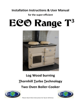
A damper is fitted to the flue connector.
Fig. 10 Damper controls
SAFETY NOTES
Please refer to Installation section of this manual to ensure
appliance has been correctly installed and is connected to a
suitable flue. Failure to do so will seriously inhibit the cooker’s
performance and could be potentially fatal.
Properly installed, operated and maintained, this appliance will not
emit fumes into the dwelling. However occasional fumes from
Flue damper closed
Flue damper open
/