Page is loading ...

Fibre Channel
Troubleshooting Guide
Sixth Edition (January 2000)
Part Number 297877-006
Compaq Computer Corporation

Notice
The information in this publication is subject to change without notice.
COMPAQ COMPUTER CORPORATION SHALL NOT BE LIABLE FOR TECHNICAL OR
EDITORIAL ERRORS OR OMISSIONS CONTAINED HEREIN, NOR FOR INCIDENTAL OR
CONSEQUENTIAL DAMAGES RESULTING FROM THE FURNISHING, PERFORMANCE, OR USE
OF THIS MATERIAL. THIS INFORMATION IS PROVIDED “AS IS” AND COMPAQ COMPUTER
CORPORATION DISCLAIMS ANY WARRANTIES, EXPRESS, IMPLIED OR STATUTORY AND
EXPRESSLY DISCLAIMS THE IMPLIED WARRANTIES OF MERCHANTABILITY, FITNESS FOR
PARTICULAR PURPOSE, GOOD TITLE AND AGAINST INFRINGEMENT.
This publication contains information protected by copyright. No part of this publication may be
photocopied or reproduced in any form without prior written consent from Compaq Computer Corporation.
© 2000 Compaq Computer Corporation.
All rights reserved. Printed in the U.S.A.
The software described in this guide is furnished under a license agreement or nondisclosure agreement.
The software may be used or copied only in accordance with the terms of the agreement.
Compaq, Deskpro, Fastart, Compaq Insight Manager, Systempro, Systempro/LT, ProLiant, ROMPaq,
QVision, SmartStart, NetFlex, QuickFind, PaqFax, ProSignia, registered United States Patent and
Trademark Office.
Neoserver, Netelligent, Systempro/XL, SoftPaq, QuickBlank, QuickLock are trademarks and/or service
marks of Compaq Computer Corporation.
Microsoft, MS-DOS, Windows, and Windows NT are registered trademarks of Microsoft Corporation.
Pentium is a registered trademark and Xeon is a trademark of Intel Corporation.
Other product names mentioned herein may be trademarks and/or registered trademarks of their respective
companies.
Compaq StorageWorks Fibre Channel Troubleshooting Guide
Sixth Edition (January 2000)
Part Number 297877-006

Contents
About This Guide
Symbols in Text..........................................................................................................vi
Compaq Technician Notes .........................................................................................vi
Where to Go for Additional Help..............................................................................vii
Telephone Numbers ..........................................................................................viii
Chapter 1
Introduction
Fibre Channel Arbitrated Loop Components in a Primary Storage System .............1-2
Compaq StorageWorks RAID Array 4000 System with Redundant Components...1-3
Fibre Channel Host Bus Adapter/P ...................................................................1-4
Fibre Channel Host Bus Adapter/E ...................................................................1-5
64-Bit/66-MHz Fibre Channel Host Adapter ....................................................1-6
RA4000 Controller............................................................................................1-7
Storage Hub 7....................................................................................................1-8
Storage Hub 12..................................................................................................1-9
GigaBit Interface Converter Module (GBIC)-Shortwave (SW)......................1-10
GigaBit Interface Converter Module (GBIC)-Longwave (LW)......................1-11
Fibre Channel Cable Option Kits ....................................................................1-11
Replacing Components in a Primary Storage System ............................................1-12
Replacing the Fibre Channel Host Bus Adapter..............................................1-12
Replacing the GBIC ........................................................................................1-12
Replacing the RA4000 Controller without RA4000 Redundant Controller....1-13
Replacing the RA4000 Controller with Redundant Controller .......................1-15
Fibre Channel Arbitrated Loop Components in a Secondary Storage System .......1-17
Fibre Channel Host Bus Adapter/P .................................................................1-17
Storage Hub 12................................................................................................1-17
Fibre Channel Tape Controller........................................................................1-19
Fibre Channel Tape Controller II ....................................................................1-20
GigaBit Interface Converter Module-Shortwave.............................................1-21
Fibre Channel Cable Option Kits ....................................................................1-21
Replacing Components in a Secondary Storage System ........................................1-21
Replacing the Fibre Channel Host Bus Adapter..............................................1-21
Replacing a GBIC ...........................................................................................1-22
Replacing a Storage Hub 12............................................................................1-22
Replacing a Fibre Channel Tape Controller....................................................1-22

iv Compaq StorageWorks Fibre Channel Troubleshooting Guide
Chapter 2
Fibre Channel Fault Isolation Utility
Installing the Utility..................................................................................................2-1
Running the Utility...................................................................................................2-1
Program Displays .....................................................................................................2-2
Display of a Fibre Channel Tape Controller .....................................................2-3
Loop Error Histogram Display..........................................................................2-4
Display of a FC-AL with a Missing Fibre Channel Tape Controller ................2-5
Uninitialized Fibre Channel Arbitrated Loop Display ......................................2-6
Information and Updates...................................................................................2-6
Chapter 3
Diagnostics
Compaq Fibre Channel Diagnostics for Windows CE .............................................3-1
Compaq Fibre Channel Diagnostics for Windows 95/98 .........................................3-1
Compaq Fibre Channel Backup Diagnostics for Windows NT................................3-2
Installing Compaq Fibre Channel Diagnostics for Windows CE .............................3-3
Installing Compaq Fibre Channel Diagnostics for Windows 95 or 98.....................3-4
Installing Compaq Fibre Channel Backup Diagnostics for Windows NT................3-4
Chapter 4
StorageWorks RAID Array 4000 and 4100 Troubleshooting Flow Charts
Overview of the Troubleshooting Flow Charts ........................................................4-2
Verify System Operation..........................................................................................4-4
Determine a Bad Link ..............................................................................................4-6
Some Fibre Channel Array Controllers Are Detected ..............................................4-7
Visual and Physical Inspection of the FC_AL........................................................4-10
Checking the Link Between the Storage Hub and the Fibre Channel
Array Controller .....................................................................................................4-12
Checking the Link Between the Storage Hub and the Fibre Channel Host Bus
Adapter...................................................................................................................4-15
Fibre Channel Loopback Test ................................................................................4-17
Chapter 5
Secondary Storage System Troubleshooting Flow Charts
Overview of the Troubleshooting Flow Charts ........................................................5-2
Verifying FC_AL Operation ....................................................................................5-4
Determining a Bad Link ...........................................................................................5-6
Some Fibre Channel Tape Controllers are Detected ................................................5-7
Visual and Physical Inspection of the FC_AL..........................................................5-9
Checking the Link Between the Storage Hub 12 and the Fibre Channel Host Bus
Adapter...................................................................................................................5-11
C .............................................................................................................................5-13

About This Guide v
Appendix A
Primary and Secondary Storage System LEDs
Fibre Channel Host Bus Adapters ...........................................................................A-1
RA4000 Controller..................................................................................................A-2
Storage Hub 7..........................................................................................................A-3
Storage Hub 12........................................................................................................A-4
Fibre Channel Tape Controller................................................................................A-6
Fibre Channel Tape Controller II ............................................................................A-7
Appendix B
GBIC and Fibre Channel Cable Connector Cleaning Considerations
Index

About This Guide
This guide is designed to be used as step-by-step instructions for installation and as a reference
for operation, troubleshooting, and future upgrades.
WARNING: To reduce the risk of personal injury from electrical shock and hazardous energy
levels, only authorized service technicians should attempt to repair this equipment. Improper
repairs could create conditions that are hazardous.
IMPORTANT: The installation of options and servicing of this product shall be performed by individuals
who are knowledgeable of the procedures, precautions, and hazards associated with equipment
containing hazardous energy circuits.
Symbols in Text
These symbols may be found in the text of this guide. They have the following meanings.
WARNING: Text set off in this manner indicates that failure to follow directions in the warning
could result in bodily harm or loss of life.
CAUTION: Text set off in this manner indicates that failure to follow directions could result in
damage to equipment or loss of information.
IMPORTANT: Text set off in this manner presents clarifying information or specific instructions.
NOTE: Text set off in this manner presents commentary, sidelights, or interesting points of information.
Compaq Technician Notes
WARNING: Only authorized technicians trained by Compaq should attempt to repair this
equipment. All troubleshooting and repair procedures are detailed to allow only
subassembly/module level repair. Because of the complexity of the individual boards and
subassemblies, no one should attempt to make repairs at the component level or to make
modifications to any printed wiring board. Improper repairs can create a safety hazard. Any
indications of component replacement or printed wiring board modifications may void any
warranty.

vii Compaq StorageWorks Fibre Channel Troubleshooting Guide
WARNING: To reduce the risk of personal injury from electrical shock and hazardous energy
levels, do not exceed the level of repair specified in these procedures. Because of the
complexity of the individual boards and subassemblies, do not attempt to make repairs at the
component level or to make modifications to any printed wiring board. Improper repairs could
create conditions that are hazardous.
WARNING: To reduce the risk of personal injury from electric shock or damage to the
equipment:
■ If the system has multiple power supplies, disconnect power from the system by
unplugging all power cords from the power supplies.
■ Do not disable the power cord grounding plug. The grounding plug is an important safety
feature.
■ Plug the power cord into a grounded (earthed) electrical outlet that is easily accessible at
all times.
CAUTION: To properly ventilate your system, you must provide at least 12 inches (30.5 cm) of
clearance at the front and back of the computer.
Where to Go for Additional Help
In addition to this guide, the following information sources are available:
■ User Documentation
■ Compaq Service Quick Reference Guide
■ Service Training Guides
■ Compaq Service Advisories and Bulletins
■ Compaq QuickFind
■ Compaq Insight Manager
■ Compaq Download Facility: Call 1-281-518-1418

About This Guide viii
Telephone Numbers
For the name of your nearest Compaq Authorized Reseller:
■ In the United States, call 1-800-345-1518
■ In Canada, call 1-800-263-5868
For Compaq technical support:
■ In the United States and Canada, call 1-800-386-2172
■ For Compaq technical support phone numbers outside the United States and Canada, visit
the Compaq website:
http://www.compaq.com.

Chapter 1
Introduction
The Compaq StorageWorks Fibre Channel Troubleshooting Guide provides a description of
Compaq StorageWorks RAID Array 4000 and 4100 components for primary and Enterprise
Backup Solution components for secondary storage systems. It also provides a description of the
Compaq Fibre Channel Fault Isolation Utility, the Fibre Channel Diagnostics Utility, and
includes detailed troubleshooting flow charts to help isolate problems on a Fibre Channel
Arbitrated Loop (FC-AL).
The Compaq Fibre Channel Fault Isolation Utility is used to verify the installation and operation
of a new or existing FC-AL. The Fibre Channel Fault Isolation Utility displays all devices that
are logged on the FC-AL properly and tests for link errors within the FC-AL.
After determining a suspected faulty component, additional troubleshooting details are available
in that component’s installation or user guide.

1-2 Compaq StorageWorks Fibre Channel Troubleshooting Guide
Fibre Channel Arbitrated Loop Components in a
Primary Storage System
NOTE: Although RA4000(s) are illustrated throughout this guide, features also apply to RA4100(s).
A typical Fibre Channel Arbitrated Loop for a primary storage system consists of the following:
■ One to eight Fibre Channel Host Bus Adapters (PCI) per server
■ At least one Storage Hub 7 or Storage Hub 12
■ At least one Compaq RA4000 consisting of at least one RA4000 Controller and several
hot-pluggable SCSI hard drives
■ Two longwave or shortwave GigaBit Interface Converter (GBIC) modules per Fibre
Channel cable link
■ Multi-mode or single mode Fibre Channel cables. One cable is connected between the
Storage Hub 7 or Storage Hub 12 and each component on the FC-AL.
Server
Fibre Array
Rack-Mountable
Fibre Array
(Tower)
Fibre Channel
Storage Hub 7
Gigabit Interface
Converter
Figure 1-1. Compaq Fibre Channel Primary Storage System with RA4000(s)

Introduction 1-3
Table 1-1
FC-AL Components in a Primary Storage System
Reference Component
Server
RA4000 Rack-Mountable
RA4000 (Tower)
Fibre Channel Storage Hub 7
GigaBit Interface Converter
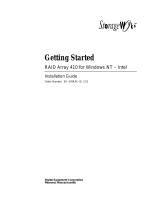
Compaq StorageWorks RAID Array 4000 System with
Redundant Components
A Compaq StorageWorks RAID Array 4000 system with redundant components consists of:
■ Two Fibre Channel Host Bus Adapters (PCI only)
■ Two storage hubs (7 or 12)
■ At least one Compaq RA4000 consisting of two RA4000 Controllers and several hot-
pluggable SCSI hard drives
■ Two longwave or shortwave GigaBit Interface Converter (GBIC) modules per Fibre
Channel cable link
■ Multi-mode or single mode Fibre Channel cables. One cable is connected between the
Storage Hub 7 or Storage Hub 12 and each component on the FC-AL.
1
2
3
3
5
1
2
6
3
4
Figure 1-2. Compaq Fibre Channel Primary Storage System with two RA4000(s)

1-4 Compaq StorageWorks Fibre Channel Troubleshooting Guide
Table 1-2
Fibre Channel Primary Storage System with Two RA4000s
Reference Component
RA4000 Controller
RA4000
GigaBit Interface Converters
Fibre Channel Host Bus Adapter
Fibre Channel Storage Hub 7 or 12
Server
Fibre Channel Host Bus Adapter/P
The Fibre Channel Host Bus Adapter/P is installed in a server with a Peripheral Component
Interconnect (PCI) local bus. The Fibre Channel Host Bus Adapter/P provides an interface
between the PCI bus in the server and the Fibre Channel Arbitrated Loop (FC-AL).
The PCI bus is a high-performance, 32-bit bus with multiplexed address and data lines, and
parity information. It provides a high-speed (up to 132 MB/sec) path between the system board
and the Fibre Channel Host Bus Adapter/P. The Fibre Channel Host Bus Adapter/P is a PCI Bus
Master device and conforms to the current PCI Local Bus Specification.
The Fibre Channel Host Bus Adapter/P requires the installation of a GigaBit Interface Converter
(GBIC) module before the Fibre Channel cable is connected.
Figure 1-3. Fibre Channel Host Bus Adapter/P

Introduction 1-5
Fibre Channel Host Bus Adapter/E
The Fibre Channel Host Bus Adapter/E was designed for use in a server equipped with the
EISA expansion bus. The Fibre Channel Host Bus Adapter/E, under the control of the operating
system and dedicated device drivers, provides an interface between the EISA bus in the server
and a (FC-AL).
The EISA expansion bus delivers the capabilities required by high-performance, 32-bit
expansion boards, while maintaining compatibility with existing 8- and 16-bit ISA expansion
boards. The Fibre Channel Host Bus Adapter/E takes advantage of the EISA architecture by
performing 32-bit bus master-burst transfers.
The Fibre Channel Host Bus Adapter/E requires the installation of a GBIC module, in the
receptacle provided, before the Fibre Channel cable is connected.
Figure 1-4. Fibre Channel Host Bus Adapter/E

1-6 Compaq StorageWorks Fibre Channel Troubleshooting Guide
64-Bit/66-MHz Fibre Channel Host Adapter
The 64-Bit/66-MHz Fibre Channel Host Adapter is installed in a server with a PCI local bus and
provides an interface between the PCI bus in the server and Fibre Channel-connected external
storage systems.
The 64-Bit/66-MHz Fibre Channel Host Adapter interface to the server is the Peripheral
Component Interconnect (PCI) bus. The PCI interface is a high-performance, 64-Bit/66-MHz
bus with multiplexed address and data lines, and parity information. It provides a high-speed (up
to 528 MB/s) path between the system board and the Host Adapter. The 64-Bit/66-MHz Fibre
Channel Host Adapter is a PCI Bus Master device and conforms to the current PCI Local Bus
Specification.
The Host Adapter requires the installation of a GigaBit Interface Converter (GBIC) module
before the Fibre Channel cable is connected. The GBIC converts electrical signals to optical
signals, and vice versa, for transmission across the Fibre Channel media. The Fibre Channel
cable connector is plugged into the installed GBIC module.
Figure 1-5. 64-Bit/66-MHz Fibre Channel Host Adapter

Introduction 1-7
RA4000 Controller
The RA4000 Controller is a drive array controller designed to be installed in the Compaq
StorageWorks RA4000 and RA4100. The RA4000 Controller supports Fast-SCSI-2, Fast-Wide
SCSI-2, or Wide-Ultra SCSI-3 hot-pluggable hard drives. The RA4000 comes equipped with
one RA4000 Controller installed. A second RA4000 Controller may be added for a redundant
configuration. Refer to the Compaq StorageWorks RAID 4000 User Guide (P/N 340428-001) or
Compaq StorageWorks RAID 4100 User Guide (P/N146297-001) for more information about
configuration.
Transmit
LED
Serial Debug
Port
Receive
LED
GBIC
Receptacle
15 14 13 12 11 10 9 8
76 54 32 10
Figure 1-6. RA4000 Controller
Features
The advanced features supported by the RA4000 Controller include:
■ Support for RAID 0, 1, 4, and 5 fault tolerance options
■ Fibre Channel support for connection to the server
■ Support for Fast-SCSI-2, Fast-Wide SCSI-2, or Wide-Ultra SCSI-3 hot-pluggable hard
drives
■ Online capacity expansion, volume extension, RAID migration, and stripe size migration
■ Removable Array Accelerator—battery-backed, configurable 16-MB or 48-MB
Read/Write Cache with ECC (Error Checking and Correcting) memory, along with a
16-MB Read Cache on the controller board
■ Performance monitoring through Compaq Insight Manager
■ Automatic performance tuning
■ Pre-failure notification on hard drives
■ Array Configuration Utility
■ Read-ahead caching
■ Tagged command queuing
■ Multiple logical drives per drive array

1-8 Compaq StorageWorks Fibre Channel Troubleshooting Guide
Storage Hub 7
The Compaq Fibre Channel Storage Hub 7 functions as the central point of interconnect for the
FC-AL. The Storage Hub 7 has seven I/O ports located on the rear of the unit.
Figure 1-7. Compaq Fibre Channel Storage Hub 7
Features
The Compaq Storage Hub 7 includes the following features:
■ Versatility—seven user-configurable media interface ports
■ Scalability—add or modify the loop as requirements dictate
■ Expandability—supports up to six storage devices per Fibre Channel Host Bus Adapter
■ Spatial economy—takes up only 1U of rack space
■ Compatibility—adheres to the ANSI FC-AL standard
■ Convenience—standalone or rack-mountable models
Table 1-3
Functional Specifications
Function Value
Data rate 1062.5 Mbaud
Data format 8 bit/10 bit
Number of ports 7
AC input power range 100 to 250 VAC, 50 to 60 Hz
Power consumption <25 Watts (all ports empty)
Temperature
Operating: 0 °C to 50 °C
Humidity Operating: 5% to 95%, non-condensing

Introduction 1-9
Storage Hub 12
The Storage Hub 12 continuously monitors and automatically configures devices added or
removed from the FC-AL. Adding valid FC-AL nodes is a plug-and-play operation. FC-AL
nodes that are missing or inoperative are detected, and the data is automatically routed to the
next operational port and node on the FC-AL.
The Storage Hub 12 is transparent to the data passing through it. It does not consume any
FC-AL addresses. Because of the intelligent signal detection tests, only valid Fibre Channel
devices will be connected to the FC-AL. When devices are added to the FC-AL, the Storage
Hub 12 will automatically test the new device and accept it into the FC-AL. Faulty devices will
be dropped by the Storage Hub 12 and dynamic node addressing will maintain the overall
FC-AL integrity.
Figure 1-8. Compaq Fibre Channel Storage Hub 12
Features
■ Expandability and Performance—supports 12 GigaBit Interface Converter modules
■ Flexibility—adheres to the ANSI FC-AL standard
■ Intelligent Port Control—provides multiple data checks without affecting performance
■ Ease of Use—provides port-bypass circuitry flexibility and simplifies central wiring
management

1-10 Compaq StorageWorks Fibre Channel Troubleshooting Guide
GigaBit Interface Converter Module (GBIC)-Shortwave (SW)
The shortwave GBIC module converts electrical signals to optical serial signals for transmission
across the FC-AL and vice versa. The Fibre Channel cable connector is plugged into the
installed GBIC module.
A GBIC-shortwave module is useable at the following locations on the FC-AL:
■ The Fibre Channel Host Bus Adapter/E or Fibre Channel Host Bus Adapter/P
■ The RA4000 Controller
■ At each port connector used in the Storage Hub 7 or Storage Hub 12
Figure 1-9. GBIC SW module
Table 1-4
GBIC-SW Module Specifications
Feature Description
Compliance Fibre Channel FC-PH-2 physical layer option
100-M5-SN-1
Baud rate 1062.5 Mbaud
Fibre short wave
50 µm dia. (preferred) or 62.5 µm
Laser 780 nm (non-OFC)
Optical connector interface Dual SC
Distance
50 µm-2 to 500 meters
62.5 µm-2 to 300 meters

Introduction 1-11
GigaBit Interface Converter Module (GBIC)-Longwave (LW)
The longwave GBIC modules must be connected to your server with a single-mode Fibre
Channel cable. Only a Fibre Channel test cable is provided with this kit. A list of Fibre Channel
cable suppliers can be found at the following website address:
http://www.compaq.com/fibrechannel.
IMPORTANT: To ensure product integrity, Compaq recommends a 9/125 µm single mode Fibre Channel
cable that complies with Bellcore GR409. The cable assembly should be terminated with SC Duplex
Connectors at each end, which are NNT-SC, Bellcore 326, and IEC-874-19 compliant.
Fibre Channel Cable Option Kits
Multi-mode Fibre Channel cables are shipped with the Fibre Channel Host Bus Adapter option
kits and the RA4000 kits.
Five multi-mode Fibre Channel cable option kits are also available if different lengths are
required for your configuration. Each cable option kit contains one Fibre Channel cable with
connectors. The option kits are:
■ 2-meter multi-mode Fibre Channel Cable option kit #234457-B21
■ 5-meter multi-mode Fibre Channel Cable option kit #234457-B22
■ 15-meter multi-mode Fibre Channel Cable option kit #234457-B23
■ 30-meter multi-mode Fibre Channel Cable option kit #234457-B24
■ 50-meter multi-mode Fibre Channel Cable option kit #234457-B25
Figure 1-10. Fibre Channel cable with connector

1-12 Compaq StorageWorks Fibre Channel Troubleshooting Guide
Replacing Components in a Primary Storage System
This section describes the steps required to replace FC-AL components in a StorageWorks
RAID Array 4000 or 4100 storage system. Refer to the Compaq StorageWorks Fibre Channel
Host Bus Adapter Installation Guide and Compaq StorageWorks RAID 4000 User Guide or
Compaq StorageWorks RAID 4100 User Guide for details.
Replacing the Fibre Channel Host Bus Adapter
When a Fibre Channel Host Bus Adapter fails in a non PCI Hot-Plug slot:
1. Perform a normal system shutdown of the server.
2. Power down the RA4000(s) or RA4100(s) attached to the failed Fibre Channel Host Bus
Adapter.
3. Remove the GBIC from the failed Fibre Channel Host Bus Adapter.
4. Remove the failed Fibre Channel Host Bus Adapter.
5. Install a new Fibre Channel Host Bus Adapter.
6. Install the GBIC that was removed in step 3, with the cable still attached.
7. Apply power to the RA4000(s) or RA4100(s).
8. Apply power to the server.
When a Fibre Channel Host Bus Adapter/P fails in a PCI Hot Plug slot:
1. Power down the PCI Hot Plug slot.
2. Remove the Fibre Channel cable and GBIC from the failed Fibre Channel Host Bus
Adapter.
3. Remove the failed Fibre Channel Host Bus Adapter.
4. Install the new Fibre Channel Host Bus Adapter.
5. Install the GBIC and Fibre Channel cable.
6. Power on the PCI Hot Plug slot.
Replacing the GBIC
To remove a GBIC module:
1. Remove the Fibre Channel cable from the failed GBIC. Carefully remove the GBIC
module from the receptacle on the equipment.
2. Install a GBIC into the receptacle on the equipment. The GBIC can only be installed one
way because the GBIC and the guide rails inside the equipment are keyed.
3. Install the Fibre Channel cable connector into the receptacle on the GBIC module. The
GBIC and the Fibre Channel cable connector are keyed to prevent an improper
installation.
/