Page is loading ...

Intel
®
Server System SR1600UR
Technical Product Specification
Intel order number E45725-010
Revision 1.8
April, 2011
Enterprise Platforms and Services Division - Marketing

Revision History Intel® Server System SR1600UR TPS
ii Intel order number E45725-010 Revision 1.8
Revision History
Date
Revision Number
Modifications
March 2009 1.0
Initial release.
October 2009 1.1
Updated section 7.3 - Control Panel Connectors.
January 2010 1.2
Update section 2.5 - NIC Connectors.
April 2010 1.3
Updated section 2.5 - System Board Overview.
Removed CCC Certification.
July 2010 1.4
Updated section 2 - Product Overview,
Added section 2.1.1 - Processor Support.
October 2010 1.5
Updated section 2.1.1 - Processor Support.
December 2010
1.6
Updated section 2.1 - Product Overview.
Removed section 4.4 - DIMM Blank Population.
1.7
Updated section 2.1 - Product Overview.
April 2011 1.8
Updated section 2.1 - Product Overview.
Disclaimers
Information in this document is provided in connection with Intel
®
products. No license, express or implied, by
estoppel or otherwise, to any intellectual property rights is granted by this document. Except as provided in Intel
®
’s
Terms and Conditions of Sale for such products, Intel
®
assumes no liability whatsoever, and Intel
®
disclaims any
express or implied warranty, relating to sale and/or use of Intel
®
products including liability or warranties relating to
fitness for a particular purpose, merchantability, or infringement of any patent, copyright or other intellectual property
right. Intel
®
products are not intended for use in medical, life saving, or life sustaining applications. Intel
®
may make
changes to specifications and product descriptions at any time, without notice.
Designers must not rely on the absence or characteristics of any features or instructions marked "reserved" or
"undefined." Intel
®
reserves these for future definition and shall have no responsibility whatsoever for conflicts or
incompatibilities arising from future changes to them.
The Intel
®
Server System SR1600UR may contain design defects or errors known as errata which may cause the
product to deviate from published specifications.
Current characterized errata are available on request.
This document and the software described in it are furnished under license and may only be used or copied in
accordance with the terms of the license. The information in this manual is furnished for informational use only, is
subject to change without notice, and should not be construed as a commitment by Intel Corporation. Intel
Corporation assumes no responsibility or liability for any errors or inaccuracies that may appear in this document or
any software that may be provided in association with this document.
Except as permitted by such license, no part of this document may be reproduced, stored in a retrieval system, or
transmitted in any form or by any means without the express written consent of Intel Corporation.
Intel, Pentium and Xeon are trademarks or registered trademarks of Intel Corporation.
*Other brands and names may be claimed as the property of others.
Copyright © Intel Corporation 2008–2011.
Portions Copyright © 2005–2011 by LSI Corporation.

Intel® Server System SR1600UR TPS Table of Contents
Revision 1.8 Intel order number E45725-010
iii
Table of Contents
1. Introduction ........................................................................................................................ 1
1.1 Chapter Outline ...................................................................................................... 1
1.2 Server Board Use Disclaimer ................................................................................. 2
2. Product Overview ............................................................................................................... 3
2.1.1 Processor Support ................................................................................................. 5
2.2 System Overview ................................................................................................... 7
2.3 System Dimensions ............................................................................................... 7
2.4 System Components .............................................................................................. 8
2.5 Hard Drive and Peripheral Bays ............................................................................. 9
2.6 System Board Overview ....................................................................................... 10
2.7 Front Bezel Support ............................................................................................. 14
2.8 Rack and Cabinet Mounting Options .................................................................... 15
3. Power Subsystem............................................................................................................. 16
3.1 Mechanical Overview ........................................................................................... 16
3.2 Output Connectors ............................................................................................... 17
3.2.1 P1 –
Main Power Connector ................................................................................. 17
3.2.2 P2 – Processor Power Connector ........................................................................ 18
3.2.3 P3 – Backplane Connector ................................................................................... 18
3.2.4 P4 – Power Signal Connector .............................................................................. 18
3.2.5 P5 – Slimline SATA Optical Disk Drive (SSATA ODD) Power Connector ............. 19
3.2.6 Fixed SATA Hard Drive Power Connectors .......................................................... 19
3.3 Efficiency.............................................................................................................. 20
3.4 AC Input Voltage Requirement ............................................................................. 20
3.5 Protection Circuits ................................................................................................ 20
3.5.1 Over-current Protection (OCP) ............................................................................. 21
3.5.2 Over-voltage Protection (OVP) ............................................................................. 21
3.5.3 Over-temperature Protection (OTP) ..................................................................... 22
3.6 Power Supply Status LED .................................................................................... 22
3.7 AC Power Cord Specification Requirements ........................................................ 22
4. Cooling Subsystem .......................................................................................................... 24
4.1 Five-fan Module ................................................................................................... 24

Table of Contents Intel® Server System SR1600UR TPS
iv Intel order number E45725-010 Revision 1.8
4.2 Power Supply Fans .............................................................................................. 26
4.3 CPU Air Duct and Air Baffle ................................................................................. 26
4.4 Drive Bay Population ............................................................................................ 27
5. Peripheral Support ........................................................................................................... 28
5.1 USB Floppy Drive Support ................................................................................... 28
5.2 Optical Drive Support ........................................................................................... 29
6. Hard Disk Drive Support .................................................................................................. 30
6.1 Hard Drive Trays .................................................................................................. 30
6.2 Fixed Mount Hard Drive Support .......................................................................... 31
6.3 Hot-swap Hard Drive Support ............................................................................... 31
6.3.1 Backplane Feature Set ......................................................................................... 32
6.3.2 LED Support ........................................................................................................ 38
6.3.3 Backplane Connector Definitions ......................................................................... 38
6.4 Enclosure Management Cabling for Passive Backplane ...................................... 45
7. Standard Control Panel .................................................................................................... 46
7.1 Control Panel Buttons .......................................................................................... 46
7.2 Control Panel LED Indicators ............................................................................... 47
7.2.1 Power/Sleep LED ................................................................................................. 48
7.2.2 System Status LED .............................................................................................. 48
7.2.3 Drive Activity LED................................................................................................. 49
7.2.4 System Identification LED .................................................................................... 49
7.3 Control Panel Connectors .................................................................................... 50
8. Intel
®
Local Control Panel ................................................................................................ 51
8.1 LED Functionality ................................................................................................. 52
8.1.1 Power/Sleep LED ................................................................................................. 52
8.1.2 System Status LED .............................................................................................. 53
8.1.3 Drive Activity LED................................................................................................. 53
8.1.4 System Identification LED .................................................................................... 54
9. PCI Riser Cards and Assembly ....................................................................................... 55
10. Environmental Specifications ......................................................................................... 56
10.1 System Level Environmental Limits ...................................................................... 56
10.2 Serviceability and Availability ................................................................................ 56
10.3 Replacing the Backup Battery .............................................................................. 57
11. Regulatory and Certification Information ....................................................................... 58

Intel® Server System SR1600UR TPS Table of Contents
Revision 1.8 Intel order number E45725-010
v
11.1 Product Regulatory Compliance ........................................................................... 58
11.1.1 Product Safety Compliance .................................................................................. 58
11.1.2 Product EMC Compliance – Class A Compliance ................................................ 59
11.1.3 Product Ecology Compliance ............................................................................... 59
11.1.4 Certifications/Registrations/Declarations .............................................................. 59
11.2 Product Regulatory Compliance Markings ........................................................... 60
11.3 Rack Mount Installation Guidelines ...................................................................... 62
11.4 Power Cord Usage Guidelines ............................................................................. 64
11.5 Electromagnetic Compatibility Notices ................................................................. 64
11.5.1 FCC Verification Statement (USA) ....................................................................... 64
11.5.2 ICES-003 (Canada) .............................................................................................. 65
11.5.3 Europe (CE Declaration of Conformity) ................................................................ 65
11.5.4 VCCI (Japan) ....................................................................................................... 65
11.5.5 BSMI (Taiwan) ..................................................................................................... 66
11.5.6 KCC (Korea) ........................................................................................................ 66
11.6 Regulated Specified Components ........................................................................ 66
Appendix A: Integration and Usage Tips .............................................................................. 68
Appendix B: POST Code Diagnostic LED Decoder .............................................................. 69
Appendix C: POST Code Errors ............................................................................................. 72
Glossary .................................................................................................................................. 80
Reference Documents ............................................................................................................ 81

List of Figures Intel® Server System SR1600UR TPS
vi Intel order number E45725-010 Revision 1.8
List of Figures
Figure 1. Top Down View – Hot-Swap Drive SKU Shown ........................................................... 7
Figure 2. Major Chassis Components ......................................................................................... 8
Figure 3. Drive Bay Overview ...................................................................................................... 9
Figure 4. Intel
®
Server Board S5520UR .................................................................................... 10
Figure 5. Intel
®
Server Board S5520UR Components ............................................................... 11
Figure 6. Back Panel Feature Overview .................................................................................... 12
Figure 7. Intel
®
Light-Guided Diagnostic LEDs - Server Board .................................................. 13
Figure 8. Optional Front Bezel .................................................................................................. 14
Figure 9. Front Bezel Options ................................................................................................... 15
Figure 10. Power Supply Mechanical Drawing .......................................................................... 16
Figure 11. AC Power Cord ........................................................................................................ 23
Figure 12. Fan Module Assembly .............................................................................................. 24
Figure 13. Air Baffle .................................................................................................................. 26
Figure 14. Hot-swap Hard Drive Tray with Drive Blank Installed ............................................... 27
Figure 15. View of Slimline Drive Bay ....................................................................................... 28
Figure 16. Intel
®
Server System SR1600UR Peripheral Bay Configuration Options .................. 30
Figure 17. Fixed Drive Tray with Drive Blank Installed .............................................................. 30
Figure 18. Hot-swap Hard Drive Tray Assembly ....................................................................... 31
Figure 19. Hot-swap Passive SAS/SATA Backplane Layout ..................................................... 33
Figure 20. Active SAS Backplane Layout .................................................................................. 34
Figure 21. Hot-swap Passive SAS/SATA Backplane Functional Diagram ................................. 35
Figure 22. Hot-swap Active SAS Backplane Functional Diagram .............................................. 35
Figure 23. LSISAS1064E SAS Controller Functional Diagram .................................................. 36
Figure 24. Bridge Board ............................................................................................................ 39
Figure 25. Standard Control Panel Assembly Module ............................................................... 46
Figure 26. Control Panel Buttons .............................................................................................. 46
Figure 27. Control Panel LED Indicators ................................................................................... 47
Figure 28. Intel
®
Local Control Panel Assembly Module ............................................................ 51
Figure 29. Intel
®
Local Control Panel Overview ......................................................................... 51
Figure 30. PCI Riser Card Assembly ........................................................................................ 55
Figure 31. 1U Full-height PCI Express* Riser Card Mechanical Drawing .................................. 55

Intel® Server System SR1600UR TPS Table of Contents
Revision 1.8 Intel order number E45725-010
vii
Figure 32. Diagnostic LED Placement Diagram ........................................................................ 69

List of Tables Intel® Server System SR1600UR TPS
viii Intel order number E45725-010 Revision 1.8
List of Tables
Table 1. System Feature Set ...................................................................................................... 3
Table 2. Mixed Processor Configurations .................................................................................... 6
Table 3. Processor Support Matrix .............................................................................................. 7
Table 4. Drive Overview .............................................................................................................. 9
Table 5. Major Board Components ........................................................................................... 12
Table 6.
Cable Harness Definition ............................................................................................. 17
Table 7. P1 – Main Power Connector Pin-out ........................................................................... 17
Table 8.
P2 – Processor Power Connector Pin-out ................................................................... 18
Table 9. P3 – Backplane Power Connector ............................................................................... 18
Table 10. P4 – Power Signal Connector ................................................................................... 18
Table 11. P5
– Slimline SATA Optical Disk Drive Power Connector .......................................... 19
Table 12. SATA Power Connector ............................................................................................ 19
Table 13. Efficiency................................................................................................................... 20
Table 14. AC Input Rating ......................................................................................................... 20
Table 15. Over-current Protection (OCP) .................................................................................. 21
Table 16. Over-voltage Protection (OVP) Limits ....................................................................... 21
Table 17. LED Indicators .......................................................................................................... 22
Table 18. AC Power Cord Specifications .................................................................................. 22
Table 19. Non-redundant Cooling Zones .................................................................................. 25
Table 20. Individual Fan Assembly Pin-out ............................................................................... 25
Table 21. 4-pin USB Floppy Connector Pin-out ......................................................................... 28
Table 22. Internal CD-ROM Connector Pin-out ......................................................................... 29
Table 23. LED Function ............................................................................................................ 38
Table 24. Hard Drive Activity LED Functionality ........................................................................ 38
Table 25. Backplane Power Connector Pin-out (J1B1) ............................................................. 39
Table 26. Bridge Board Connector Pin-out (J5A1) .................................................................... 40
Table 27. Backplane Control Panel Connector Pin-out (J9C1) .................................................. 41
Table 28. 1x10 Pin Control Panel USB Connector Pin-out (J6B1) ............................................ 42
Table 29. SAS/SATA Hard Drive Connector Pin-out (J8N1, J6N1, J3N1) ................................. 42
Table 30. SATA/SAS Drive Control Connector Pin-out (J3C1, J4B2, J4A1) .............................. 43
Table 31. 4-pin Floppy Connector Pin-out (J2B1) ..................................................................... 43

Intel® Server System SR1600UR TPS List of Tables
Revision 1.8 Intel order number E45725-010
ix
Table 32. System Fan Connector Pin-outs ................................................................................ 44
Table 33. IPMB Connector Pin-out (J1C1) ................................................................................ 44
Table 34. Add-in Card Connector Pin-out (J4B3 – Passive Only) ............................................. 45
Table 35. Control Button and Intrusion Switch Functions .......................................................... 47
Table 36. Control Panel LED Functions .................................................................................... 47
Table 37. SSI Power LED Operation ......................................................................................... 48
Table 38. Control Panel LED Operation .................................................................................... 48
Table 39. External USB Connectors (J1B1) .............................................................................. 50
Table 40. Video Connector (J1A1) ............................................................................................ 50
Table 41. Control Panel LED Functions .................................................................................... 52
Table 42. SSI Power LED Operation ......................................................................................... 52
Table 43. Control Panel LED Operation .................................................................................... 53
Table 44. System Environmental Limits Summary .................................................................... 56
Table 45. Time Estimate for System Maintenance Procedures ................................................. 56
Table 46. POST Progress Code LED Example ......................................................................... 69
Table 47. Diagnostic LED POST Code Decoder ....................................................................... 70
Table 48. POST Error Messages and Handling ........................................................................ 74
Table 49. POST Error Beep Codes ........................................................................................... 79
Table 50. Integrated BMC Beep Codes .................................................................................... 79

List of Tables Intel® Server System SR1600UR TPS
x Intel order number E45725-010 Revision 1.8
< This page is intentionally left blank. >

Intel® Server System SR1600UR TPS 0BIntroduction
Revision 1.8 Intel order number E45725-010
1
1. Introduction
This Technical Product Specification (TPS) provides system-specific information detailing the
features, functionality, and high-level architecture of the Intel
®
Server System SR1600UR. The
Intel
®
Server Board S5520UR Technical Product Specification should also be referenced to
obtain greater detail of functionality and architecture specific to the integrated server board, but
which are also supported on this server system.
In addition, design-level information for specific subsystems can be obtained by ordering the
External Product Specifications (EPS) or External Design Specifications (EDS) for a given
subsystem. EPS and EDS documents are not publicly available. They are only made available
under NDA with Intel
®
and must be ordered through your local Intel
®
representative. See the
Reference Documents section at the end of this document for a complete list of
available documents.
The Intel
®
Server System SR1600UR may contain design defects or errors known as errata,
which may cause the product to deviate from published specifications. Refer to the Intel
®
Server
Board S5520UR/Intel
®
Server System SR1600UR Specification Update for published errata.
1.1 Chapter Outline
This document is divided into the following chapters:
Chapter 1 – Introduction
Chapter 2 – Product Overview
Chapter 3 – Power Subsystem
Chapter 4 – Cooling Subsystem
Chapter 5 – Peripheral Support
Chapter 6 – Hard Disk Drive Support
Chapter 7 – Standard Control Panel
Chapter 8 – Intel
®
Local Control Panel
Chapter 9 – PCI Riser Cards and Assembly
Chapter 10 – Environmental Specifications
Chapter 11 – Regulatory and Certification Information
Appendix A – Integration and Usage Tips
Appendix B – POST Code Diagnostic LED Decoder
Appendix C – Post Code Errors
Glossary
Reference Documents

0BIntroduction Intel® Server System SR1600UR TPS
2 Intel order number E45725-010 Revision 1.8
1.2 Server Board Use Disclaimer
Intel Corporation server boards support add-in peripherals and contain a number of high-
density VLSI and power delivery components that need adequate airflow to cool. Intel
®
ensures
through its own chassis development and testing that when Intel
®
server building blocks are
used together, the fully integrated system will meet the intended thermal requirements of these
components. It is the responsibility of the system integrator who chooses not to use Intel
®
-
developed server building blocks to consult vendor datasheets and operating parameters to
determine the amount of airflow required for their specific application and environmental
conditions. Intel Corporation cannot be held responsible if components fail or the server board
does not operate correctly when used outside any of their published operating or
non-operating limits.

Intel® Server System SR1600UR TPS 1BProduct Overview
Revision 1.8 Intel order number E45725-010
3
2. Product Overview
The Intel
®
Server System SR1600UR is a rack mount 1U server system with features that are
designed to support the high-density high-performance computing server market. The system is
integrated with an Intel
®
Server Board S5520UR and is offered in two different system
configurations:
Configuration 1: Supports up to three fixed SATA hard drives,
Configuration 2: Supports hot-swap backplane options capable of supporting up to three
hot-swap SAS or SATA hard drives.
This chapter provides a high-level overview of the system features. Greater detail for each
major system component or feature is provided in the following chapters.
Table 1. System Feature Set
Feature
Description
Peripheral Interfaces
External connections:
DB-15 video connector (back)
Hot-swap hard drive system only: DB-15 video connector
(front)
RJ-45 serial Port A connector
Two RJ-45 10/100/1000 Mb network connections
Four USB 2.0 connectors (back)
One USB 1.1 connector (front)
Internal connections:
One USB 2x5 pin header, which supports two USB 2.0 ports
One low-profile USB 2x5 pin header to support low-profile USB Solid State
drives
One DH-10 Serial Port B header
Six Serial ATA (SATA) II connectors
Two I/O module Mezzanine connectors for optional I/O Module support
One RMM3 connector to support an optional Intel
®
Remote Management
Module 3
SATA Software RAID 5 Activation Key connector
One SSI-EEB compliant front panel header
One SSI-EEB compliant 24-pin main power connector
One SSI-compliant 8-pin CPU power connector
One SSI-compliant power supply SMBus connector
Video
On-board ServerEngines* LLC Pilot II Controller
Integrated 2D Video Controller
64
MB DDR2 Memory
LAN
Two 10/100/1000 Intel
®
82575 PHYs with Intel
®
I/O Acceleration Technology 2
support.

1BProduct Overview Intel® Server System SR1600UR TPS
4 Intel order number E45725-010 Revision 1.8
Feature
Description
Expansion Capabilities
One x16 PCI Express* Gen 2 PCI riser slot capable of supporting a full-length full-
height PCI Express* add-in card.
Hard Drive Options
Fixed mount hard drive system:
Three SATA drives
Hot-swap hard drive system:
Three 3.5 inch hot-swap SATA/SAS drives
Peripherals
Slimline bay for slimline SATA optical drive
One PCI Express* X16 add-in card slot (Gen 2)
Control Panel
Standard control panel
Hot-swap hard drive system only: Intel
®
Local Control Panel
LEDs and displays With standard control panel:
NIC1 Activity
NIC2 Activity
Power/Sleep
System Status
System Identification
Hard Drive Activity
Intel
®
Light-Guided diagnostics:
Fan Fault
DIMM Fault
CPU Fault
5V-STBY
System Status
System Identification
POST Code Diagnostics
Power Supply Single 600-W power supply module
Fans
Five 40x40x56-mm, non-redundant, variable-speed, dual-rotor system fans
Two non-redundant 40-mm power supply fans
System Management On-board ServerEngines* LLC Pilot II Controller
Integrated Baseboard Management Controller (Integrated BMC), IPMI 2.0
compliant
Integrated Super I/O on LPC interface
Support for Intel
®
Server Management Software 3.1

Intel® Server System SR1600UR TPS 1BProduct Overview
Revision 1.8 Intel order number E45725-010
5
2.1.1 Processor Support
The Intel
®
Server Boards S5520UR supports the following processors:
One or two Intel
®
Xeon
®
Processor 5500 Series with a 4.8 GT/s, 5.86 GT/s, or 6.4 GT/s
Intel
®
QPI link interface and Thermal Design Power (TDP) up to 95 W.
One or two Intel
®
Xeon
®
Processor 5600 Series with a 6.4 GT/s Intel
®
QPI link interface
and Thermal Design Power (TDP) up to 130 W.
Note: When configured with 130W processors,only Single & Dual Rank DIMMs are supported.
The server boards do not support previous generations of the Intel
®
Xeon
®
Processors.
For a complete updated list of supported processors, see:
http://www.intel.com/p/en_US/support/highlights/server/s5520ur. On the Support tab, look for
Compatibility and then Supported Processor List.
2.1.1.1 Processor Population Rules
Note: Although the server board does support dual-processor configurations consisting of
different processors that meet the defined criteria below, Intel
®
does not perform validation
testing of this configuation. For optimal system performance in dual-processor configurations,
Intel
®
recommends that identical processors be installed.
When using a single processor configuration, the processor must be installed into the
processor socket labeled CPU1. A terminator is not required in the second processor socket
when using a single processor configuration.
When two processors are installed, the following population rules apply:
Both processors must be of the same processor family.
Both processors must have the same front-side bus speed.
Both processors must have the same cache size.
Processors with different speeds can be mixed in a system, given the prior rules are met.
If this condition is detected, all processor speeds are set to the lowest common
denominator (highest common speed) and an error is reported.
Processor stepping within a common processor family can be mixed as long as it is
listed in the processor specification updates published by Intel Corporation.
The following table describes mixed processor conditions and recommended actions for all
Intel
®
server boards and systems that use the Intel
®
5520 Chipset. The errors fall into one of the
following two categories:
Fatal: If the system can boot, it goes directly to the error manager, regardless of
whether the Post Error Pause setup option is enabled or disabled.
Major: If the Post Error Pause setup option is enabled, system goes directly to the
error manager. Otherwise, the system continues to boot and no prompt is given for the
error. The error is logged to the error manager.

1BProduct Overview Intel® Server System SR1600UR TPS
6 Intel order number E45725-010 Revision 1.8
Table 2. Mixed Processor Configurations
Error
Severity
System Action
Processor family not
identical
Fatal
The BIOS detects the error condition and responds as follows:
Logs the error into the system event log (SEL).
Alerts the Integrated BMC of the configuration error with an IPMI
command.
Does not disable the processor.
Displays “0194: Processor family mismatch detected” message
in the error manager.
Halts the system.
Processor cache not
identical
Fatal
The BIOS detects the error condition and responds as follows:
Logs the error into the SEL.
Alerts the Integrated BMC of the configuration error with an IPMI
command.
Does not disable the processor.
Displays “0192: Cache size mismatch detected” message in the
error manager.
Halts the system.
Processor frequency (speed)
not identical
Major
The BIOS detects the error condition and responds as follows:
Adjusts all processor frequencies to lowest common
denominator.
Continues to boot the system successfully.
If the frequencies for all processors cannot be adjusted to be the
same, then the BIOS:
Logs the error into the SEL.
Displays “0197: Processor speeds mismatched” message in the
error manager.
Halts the system.
Processor microcode
missing
Fatal
The BIOS detects the error condition and responds as follows:
Logs the error into the SEL.
Alerts the Integrated BMC of the configuration error with an IPMI
command.
Does not disable processor.
Displays “816x: Processor 0x unable to apply microcode update”
message in the error manager.
Pauses the system for user intervention.
Processor Intel
®
QuickPath
Interconnect speeds not
identical
Halt
The BIOS detects the error condition and responds as follows:
Logs the error into the system event log (SEL).
Alerts the Integrated BMC of the configuration error with an IPMI
command.
Does not disable the processor.
Displays “0195: Processor Front Side Bus speed mismatch
detected” message in the error manager.
Halts the system.

Intel® Server System SR1600UR TPS 1BProduct Overview
Revision 1.8 Intel order number E45725-010
7
2.2 System Overview
Figure 1. Top Down View – Hot-Swap Drive SKU Shown
2.3 System Dimensions
Table 3. Processor Support Matrix
Height
43.3 mm
1.70 in
Width without rails
430 mm
16.9 in
Width with rails
451.6 mm
17.78 in
Depth without CMA
690.6 mm
27.19 in
Depth with CMA
844.5 mm
33.25 in
Maximum Weight
15.4 kg
34 lbs

1BProduct Overview Intel® Server System SR1600UR TPS
8 Intel order number E45725-010 Revision 1.8
2.4 System Components
A
Rack handles (optional)
H
System Fan Assembly
B
Air baffle
I
System Fan board used in fixed drive system;
Backplane used in hot-swap system
C
Power supply
J
Control panel
D
Server board
K
Hard drive bays:
• Three hard drives supported for fixed
drive system
• Three hard drives supported for hot-swap
system
E
PCI add-in riser assembly
L
Slimline drive bay
F PCI card bracket (full-height) M Front bezel (optional)
G
Processor air duct
Not shown: Bridge board (only in a hot-swap system)
Figure 2. Major Chassis Components

Intel® Server System SR1600UR TPS 1BProduct Overview
Revision 1.8 Intel order number E45725-010
9
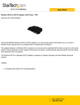
2.5 Hard Drive and Peripheral Bays
Table 4. Drive Overview
Fixed Drive System
Product Code - SR1600UR
Hot-Swap Drive System
Product Code – SR1600URHS
Slimline SATA Optical Drive
Supported
Supported
Slimline USB Floppy Drive
No Support
Supported
SATA Drives
Up to three SATA drives
Up to three SATA drives
SAS Drives
No Support
Up to three SAS drives with
the active backplane option
AF002191
A
B
D
C
A
Slimline drive bay
B Intel
®
Standard Control Panel
C
Hard Drive Status LEDs (hot-swap drives only)
D
Hard drive bays
Figure 3. Drive Bay Overview

1BProduct Overview Intel® Server System SR1600UR TPS
10 Intel order number E45725-010 Revision 1.8
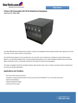
2.6 System Board Overview
Figure 4. Intel
®
Server Board S5520UR
The following figure shows the board layout of the server board. Each connector and major
component is identified by a number or letter, and a description is provided
below
the
figure.
/