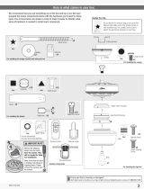
9
10
Reverse
Switch
Updraft (clockwise rotation)
creates a more indirect airow.
Updraft airow is great for
moving warm air downward.
Downdraft (counterclockwise
rotation) creates a direct breeze
and maximum cooling effect.
Ceiling fans work in two directions: downdraft
(counterclockwise rotation) and updraft
(clockwise rotation). To change the direction
of air ow, turn the fan off and let it come to a
complete stop. The reversing switch is located
inside the light xture. It can only be accessed
when the glass is removed. Slide the reversing
switch to the opposite position. Restart the fan.
Hunter Fan Company grants this limited warranty to the original purchaser of this Hunter
ceiling fan. This document can be found at www.HunterFan.com.
Thank you for choosing Hunter!
How Can Warranty Service Be Obtained?
Proof of purchase is required when requesting warranty service. The original
purchaser must present a sales receipt or other document that establishes proof of
purchase. Hunter, at its sole discretion, may accept a gift receipt. To obtain service,
contact Hunter Fan Company online or by phone.
www.HunterFan.com/Support/Contact-Us/
1-888-830-1326
Please do not ship your fan or any fan parts to Hunter. Delivery will be refused.
What Does This Warranty Cover?
Motor — Limited Lifetime Warranty
If any part of your ceiling fan motor fails during your ownership of the fan due to a
defect in material or workmanship, as determined solely by Hunter, Hunter will provide
you with a replacement fan free of charge.* The foregoing limited warranty applies only
to the motor itself and does not apply to electronic controls – such as remote control
transmitters, remote control receivers, or capacitors – used in conjunction with the
motor. Such electronic control items are included in the one-year limited warranty below.
Other — One-Year Limited Warranty
Except as otherwise indicated throughout this warranty, if any part of your Hunter ceiling
fan fails at any time within one year of the date of purchase due to a defect in material
or workmanship, as determined solely by Hunter, Hunter will provide a replacement part
free of charge.*
Light Kits — Warranty May Vary
Light kits are included in the one-year limited warranty. However, you may qualify for
additional warranty coverage if your fan includes one of the following:
• LED Light Kits — Three-Year Limited Warranty
If your LED light kit module (not including glass components) or LED bulb
fails at any time within three years of the date of purchase due to a defect
in material or workmanship, as determined solely by Hunter, Hunter will
provide a replacement part free of charge.*
* If no replacement product/part can be provided for your fan, we will provide a comparable or
superior replacement product/part at the sole discretion of Hunter.
What Does This Warranty NOT Cover?
Labor Excluded. This warranty does not cover any costs or fees associated with the labor
(including electrician’s fees) required to install, remove, or replace a fan or any fan parts.
There is no warranty for light bulbs (except where otherwise noted); remote control
batteries; fans purchased or installed outside the United States; fans owned by
someone other than the original purchaser; fans for which proof of purchase has not
been established; fans purchased from an unauthorized dealer; ordinary wear and tear;
minor cosmetic blemishes; refurbished fans; and fans that are damaged due to any
of the following: improper installation, misuse, abuse, improper care, failure to follow
Hunter instructions, accidental damage caused by the fan owner or related parties,
modications to the fan, improper or incorrectly performed maintenance or repair,
improper voltage supply or power surge, use of improper parts or accessories, failure to
provide maintenance to the fan, or acts of God (e.g. ood).
ORIGINAL PURCHASER’S SOLE AND EXCLUSIVE REMEDY FOR A CLAIM OF ANY KIND
WITH RESPECT TO THIS PRODUCT SHALL BE THE REMEDIES SET FORTH HEREIN.
HUNTER FAN COMPANY IS NOT RESPONSIBLE FOR CONSEQUENTIAL OR INCIDENTAL
DAMAGES, DUE TO PRODUCT FAILURE, WHETHER ARISING OUT OF BREACH OF
WARRANTY, BREACH OF CONTRACT, OR OTHERWISE. Some States do not allow the
exclusion or limitation of incidental or consequential damages, so the above limitation or
exclusion may not apply to you.
ANY IMPLIED WARRANTIES OF MERCHANTABILITY OR FITNESS FOR A PARTICULAR
PURPOSE APPLICABLE TO THIS PRODUCT ARE LIMITED IN DURATION TO THE PERIOD OF
COVERAGE OF THE APPLICABLE LIMITED WARRANTIES SET FORTH ABOVE. Some States
do not allow limitations on how long an implied warranty lasts, so the above limitation
may not apply to you.
How Does State Law Affect Warranty Coverage?
This warranty gives you specic legal rights. You may also have other rights which vary
from state to state.
Limited Lifetime Warranty
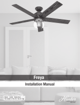
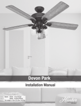
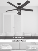
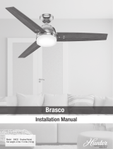
Fan style may vary.
Note: