Page is loading ...

X10SDV
Flex ATX Series
USER’S MANUAL
1.0a

The information in this user’s manual has been carefully reviewed and is believed to be accurate.
The vendor assumes no responsibility for any inaccuracies that may be contained in this document,
and makes no commitment to update or to keep current the information in this manual, or to notify
any person or organization of the updates. Please Note: For the most up-to-date version of this
manual, please see our website at www.supermicro.com.
Super Micro Computer, Inc. ("Supermicro") reserves the right to make changes to the product
described in this manual at any time and without notice. This product, including software and docu-
mentation, is the property of Supermicro and/or its licensors, and is supplied only under a license.
Any use or reproduction of this product is not allowed, except as expressly permitted by the terms
of said license.
IN NO EVENT WILL SUPER MICRO COMPUTER, INC. BE LIABLE FOR DIRECT, INDIRECT,
SPECIAL, INCIDENTAL, SPECULATIVE OR CONSEQUENTIAL DAMAGES ARISING FROM THE
USE OR INABILITY TO USE THIS PRODUCT OR DOCUMENTATION, EVEN IF ADVISED OF
THE POSSIBILITY OF SUCH DAMAGES. IN PARTICULAR, SUPER MICRO COMPUTER, INC.
SHALL NOT HAVE LIABILITY FOR ANY HARDWARE, SOFTWARE, OR DATA STORED OR USED
WITH THE PRODUCT, INCLUDING THE COSTS OF REPAIRING, REPLACING, INTEGRATING,
INSTALLING OR RECOVERING SUCH HARDWARE, SOFTWARE, OR DATA.
Any disputes arising between the manufacturer and the customer shall be governed by the laws of
Santa Clara County in the State of California, USA. The State of California, County of Santa Clara
shall be the exclusive venue for the resolution of any such disputes. Supermicro's total liability for
all claims will not exceed the price paid for the hardware product.
FCC Statement: This equipment has been tested and found to comply with the limits for a Class
A digital device pursuant to Part 15 of the FCC Rules. These limits are designed to provide
reasonable protection against harmful interference when the equipment is operated in a commercial
environment. This equipment generates, uses, and can radiate radio frequency energy and, if not
installed and used in accordance with the manufacturer’s instruction manual, may cause harmful
interference with radio communications. Operation of this equipment in a residential area is likely
to cause harmful interference, in which case you will be required to correct the interference at your
own expense.
California Best Management Practices Regulations for Perchlorate Materials: This Perchlorate
warning applies only to products containing CR (Manganese Dioxide) Lithium coin cells. “Perchlorate
Material-special handling may apply. See www.dtsc.ca.gov/hazardouswaste/perchlorate”.
WARNING: Handling of lead solder materials used in this
product may expose you to lead, a chemical known to
the State of California to cause birth defects and other
reproductive harm.
Manual Revision: 1.0a
Release Date: July 29, 2016
Unless you request and receive written permission from Super Micro Computer, Inc., you may not
copy any part of this document.
Information in this document is subject to change without notice. Other products and companies
referred to herein are trademarks or registered trademarks of their respective companies or mark
holders.
Copyright © 2016 by Super Micro Computer, Inc.
All rights reserved.
Printed in the United States of America

iii
Preface
This manual is written for system integrators, IT technicians and
knowledgeable end users. It provides information for the installation and use of the
X10SDV Flex ATX Series motherboard.
About This Motherboard
The X10SDV Flex ATX Series motherboard supports an Intel
®
Xeon/
Pentium SoC (System-on-a-Chip) D-1500 Family processor in a BGA package. The
X10SDV Flex ATX Series motherboard addresses a low-power, high-density infra-
structure need with up to 16 Cores and 128 GB of DDR4 memory, two integrated
10 Gigabit Ethernet SFP+ ports, up to 6 Gigabit Intel Ethernet ports, USB 3.0 and a
thermal design up to 65 watts. The X10SDV Flex ATX Series motherboard provides
software consistency from the data center to the storage and network edge with the
same instruction set as the robust Xeon processor.
Please refer to our website at (http://www.supermicro.com/products/) for memory
support updates. This product is intended to be installed and serviced by profes-
sional technicians.
Manual Organization
Chapter 1 describes the features, specications and performance of the mother-
board, and provides detailed information on the Intel Xeon/Pentium D-1500 Family
processor.
Chapter 2 provides hardware installation instructions. Read this chapter when in-
stalling the processor, memory modules and other hardware components into the
system. If you encounter any problems, see Chapter 3, which describes trouble-
shooting procedures for video, memory and system setup stored in the CMOS.
Chapter 4 includes an introduction to the BIOS, and provides detailed information
on running the CMOS Setup utility.
Appendix A provides BIOS Error Beep Codes.
Appendix B lists software program installation instructions.
Appendix C contains UEFI BIOS Recovery instructions.
Appendix D contains Dual Boot Block instructions.
Preface

iv
Conventions Used in the Manual:
Special attention should be given to the following symbols for proper installation and
to prevent damage done to the components or injury to yourself:
Warning: Critical information to prevent damage to the components or injury to your-
self.
Important: Important information given to ensure proper system installa-
tion or to relay safety precautions.
Note: Additional Information given to differentiate various models or to
provide instructions for correct system setup.
X10SDV Flex ATX Series Motherboard User’s Manual

v
Contacting Supermicro
Contacting Supermicro
Headquarters
Address: Super Micro Computer, Inc.
980 Rock Ave.
San Jose, CA 95131 U.S.A.
Tel: +1 (408) 503-8000
Fax: +1 (408) 503-8008
Email: [email protected] (General Information)
[email protected] (Technical Support)
Web Site: www.supermicro.com
Europe
Address: Super Micro Computer B.V.
Het Sterrenbeeld 28, 5215 ML
's-Hertogenbosch, The Netherlands
Tel: +31 (0) 73-6400390
Fax: +31 (0) 73-6416525
Email: [email protected] (General Information)
[email protected] (Technical Support)
[email protected] (Customer Support)
Web Site: www.supermicro.nl
Asia-Pacic
Address: Super Micro Computer, Inc.
3F, No. 150, Jian 1st Rd.
Zhonghe Dist., New Taipei City 235
Taiwan (R.O.C)
Tel: +886-(2) 8226-3990
Fax: +886-(2) 8226-3992
Email: [email protected]
Web Site: www.supermicro.com.tw

vi
Table of Contents
Preface
Chapter 1 Introduction
1-1 Overview ......................................................................................................... 1-1
1-2 Processor Overview ..................................................................................... 1-15
1-3 Special Features ........................................................................................... 1-16
1-4 PC Health Monitoring .................................................................................... 1-16
1-5 ACPI Features ............................................................................................... 1-17
1-6 Power Supply ................................................................................................ 1-17
Chapter 2 Installation
2-1 Standardized Warning Statements ................................................................. 2-1
Battery Handling .............................................................................................. 2-1
Product Disposal ............................................................................................. 2-3
2-2 Static-Sensitive Devices .................................................................................. 2-4
Precautions ..................................................................................................... 2-4
Unpacking ....................................................................................................... 2-4
2-3 Motherboard Installation .................................................................................. 2-5
Tools Needed .................................................................................................. 2-5
Location of Mounting Holes ............................................................................ 2-5
Installing the Motherboard .............................................................................. 2-6
2-4 Memory Support .............................................................................................. 2-7
Memory Population Guidelines ....................................................................... 2-7
Memory Installation Guidelines ....................................................................... 2-8
Installing DIMM Memory Modules ................................................................... 2-8
Removing DIMM Memory Modules ................................................................. 2-8
2-5 Connectors/IO Ports ........................................................................................ 2-9
Back panel I/O Panel ...................................................................................... 2-9
Serial Port ................................................................................................. 2-10
VGA .......................................................................................................... 2-10
Gigabit Ethernet LAN Ports .......................................................................2-11
10G SFP+/Ethernet LAN Ports .................................................................2-11
Universal Serial Bus (USB) ...................................................................... 2-12
Unit Identier Switch ................................................................................ 2-13
Front Control Panel ....................................................................................... 2-14
Front Control Panel Pin Denitions............................................................... 2-15
Power LED .............................................................................................. 2-15
Power Button ........................................................................................... 2-15
HDD LED .................................................................................................. 2-16
X10SDV Flex ATX Series Motherboard User’s Manual

vii
NIC1/NIC2 (LAN1/LAN2) .......................................................................... 2-16
Overheat (OH)/Fan Fail/PWR Fail/UID LED ............................................ 2-17
Reset Button ........................................................................................... 2-17
Power Fail LED ....................................................................................... 2-18
2-6 Connecting Cables ........................................................................................ 2-19
ATX PWR, DC PWR and HDD PWR Connectors (JPW1, JPV1, JPH1) 2-19
Fan Headers (FAN1 ~ FAN4, FANA, FANB)............................................ 2-20
Chassis Intrusion ..................................................................................... 2-20
4-pin External I
2
C BMC Header ............................................................... 2-21
DOM PWR Connector .............................................................................. 2-21
TPM Header/Port 80 Header ................................................................... 2-22
Overheat LED Header .............................................................................. 2-22
Speaker .................................................................................................... 2-23
Standby Power ......................................................................................... 2-23
Serial Link I/O Header .............................................................................. 2-24
System Management Bus Header ........................................................... 2-24
NVMe I
2
C Header ..................................................................................... 2-25
Power SMB (I
2
C) Header ......................................................................... 2-25
General Purpose I/O Header ................................................................... 2-26
2-7 Jumper Settings ............................................................................................ 2-27
Explanation of Jumpers ................................................................................ 2-27
VGA Enable .............................................................................................. 2-27
CMOS Clear ............................................................................................. 2-28
PCI-E Slot SMB Enable (I
2
C1/I
2
C2) ......................................................... 2-28
Watch Dog Timer Enable ......................................................................... 2-29
USB Wake-Up ......................................................................................... 2-29
Management Engine (ME) Recovery ...................................................... 2-30
ME Manufacturing Mode .......................................................................... 2-30
BIOS Recovery ......................................................................................... 2-31
BMC Enabled ........................................................................................... 2-31
GbE LAN Ports Enable/Disable ............................................................... 2-32
10GbE LAN Ports Enable/Disable ........................................................... 2-32
SAS Port Enable/Disable ......................................................................... 2-33
2-8 Onboard Indicators ........................................................................................ 2-34
LAN LEDs ................................................................................................. 2-34
BMC Heartbeat LED ................................................................................ 2-34
Onboard Power LED ............................................................................... 2-35
Overheat/PWR Fail/Fan Fail LED ............................................................ 2-35
Unit Identication LED .............................................................................. 2-36
Table of Contents

viii
10G LAN Activity LED .............................................................................. 2-37
10G LAN Link Status LED ....................................................................... 2-37
SAS Hearbeat LED .................................................................................. 2-38
2-9 SATA Connections ......................................................................................... 2-39
SATA Ports .............................................................................................. 2-39
SAS Ports (7TP8F/7TP4F only) ............................................................... 2-39
M.2 Socket ............................................................................................... 2-40
Mini PCI-E Slot ......................................................................................... 2-40
Chapter 3 Troubleshooting
3-1 Troubleshooting Procedures ........................................................................... 3-1
3-2 Technical Support Procedures ........................................................................ 3-3
3-3 Frequently Asked Questions ........................................................................... 3-4
3-4 Battery Removal and Installation .................................................................... 3-5
3-5 Returning Merchandise for Service................................................................. 3-6
Chapter 4 BIOS
4-1 Introduction ...................................................................................................... 4-1
4-2 Main Setup ...................................................................................................... 4-2
4-3 Advanced Setup Congurations...................................................................... 4-4
4-4 Event Logs .................................................................................................... 4-28
4-5 IPMI ............................................................................................................... 4-30
4-6 Security Settings ........................................................................................... 4-33
4-7 Boot Settings ................................................................................................. 4-36
4-8 Save & Exit ................................................................................................... 4-38
Appendix A BIOS Error Beep Codes
A-1 BIOS Error Beep Codes .................................................................................A-1
Appendix B Software Installation Instructions
B-1 Installing Software Programs ..........................................................................B-1
B-2 Installing SuperDoctor5 ...................................................................................B-2
Appendix C UEFI BIOS Recovery Instructions
C-1 An Overview to the UEFI BIOS ......................................................................C-1
C-2 How to Recover the UEFI BIOS Image (-the Main BIOS Block)....................C-1
C-3 To Recover the Main BIOS Block Using a USB-Attached Device..................C-1
Appendix D Dual Boot Block
D-1 Introduction ......................................................................................................D-1
D-2 Steps to Reboot the System by Using Jumper JBR1 ....................................D-2
X10SDV Flex ATX Series Motherboard User’s Manual

Chapter 1: Introduction
1-1
Chapter 1
Introduction
1-1 Overview
Checklist
Congratulations on purchasing your computer motherboard from an acknowledged
leader in the industry. Supermicro boards are designed with the utmost attention to
detail to provide you with the highest standards in quality and performance.
Please check that the following items have all been included with your motherboard.
If anything listed here is damaged or missing, contact your retailer.
The following items are included in the retail box:
• One (1) Supermicro Motherboard
• Four (4) SATA cables
• Four (4) Mini-SAS HD cables (7TP8F/7TP4F only)
• One (1) I/O shield
• One (1) Quick Reference Guide
Note: For your system to work properly, please follow the links below to
download all necessary drivers/utilities and the user's manual for your
motherboard.
Supermicro product manuals: http://www.supermicro.com/support/manuals/
Product Drivers and utilities: ftp://ftp.supermicro.com/
If you have any questions, please contact our support team at support@supermicro.
com.

1-2
X10SDV Flex ATX Series Motherboard User’s Manual
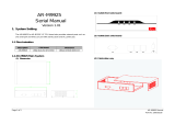
X10SDV-7TP8F Motherboard Image
Note: All graphics shown in this manual were based upon the latest PCB Revision
available at the time of publishing of the manual. The motherboard you have re-
ceived may or may not look exactly the same as the graphics shown in this manual.

Chapter 1: Introduction
1-3
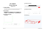
X10SDV-7TP4F Motherboard Image
X10SDV-4C-7TP4F Motherboard Image
X10SDV-2C-7TP4F Motherboard Image
Note: All graphics shown in this manual were based upon the latest PCB Revision
available at the time of publishing of the manual. The motherboard you have re-
ceived may or may not look exactly the same as the graphics shown in this manual.

1-4
X10SDV Flex ATX Series Motherboard User’s Manual
X10SDV-TP8F Motherboard Image
X10SDV-2C-TP8F Motherboard Image
Note: All graphics shown in this manual were based upon the latest PCB Revision
available at the time of publishing of the manual. The motherboard you have re-
ceived may or may not look exactly the same as the graphics shown in this manual.

Chapter 1: Introduction
1-5
X10SDV-2C-TP4F Motherboard Image
Note: All graphics shown in this manual were based upon the latest PCB Revision
available at the time of publishing of the manual. The motherboard you have re-
ceived may or may not look exactly the same as the graphics shown in this manual.

1-6
X10SDV Flex ATX Series Motherboard User’s Manual
X10SDV-4C+-TP4F Motherboard Image
Note: All graphics shown in this manual were based upon the latest PCB Revision
available at the time of publishing of the manual. The motherboard you have re-
ceived may or may not look exactly the same as the graphics shown in this manual.

Chapter 1: Introduction
1-7
X10SDV Flex ATX Series Motherboard Layout
Important Notes to the User
1. See Chapter 2 for detailed information on jumpers, I/O ports and JF1 front
panel connections.
2. " " indicates the location of "Pin 1". Jumpers not indicated are for testing
only.
BAR CODE
JTGLED1
X10SDV-TP8F
REV:1.01
DIMMB1
DIMMA2
DIMMB2
DIMMA1
BT1
LED3
C
LEDM1
A
C
LED8
C
LED7
A
C
JITP1
DESIGNED IN USA
COM1
1
PRESS FIT
JPS1
JPG1
JWD1
JPME2
JBR1
JPUSB1
JPL1
JPL2
JPME1
JPL3
JPTG1
JI2C2
JI2C1
JSMB1
JPB1
JNVI2C1
JIPMB1
LEDT4
A
C
LEDT2
A
C
LEDT3
A
C
LEDT1
A
C
LEDS1
A
MP_SRW1
MP_SRW2
JMP1
FAN4
FANA
FANB
FAN1
FAN3
FAN2
JSTBY1
JLANLED1
I-SGPIO1
I-SATA3
I-SATA2
I-SATA0
I-SATA1
JSD1
JSD2
JOH1
JL1
JTPM1
JF1
JSAS4
PRESS FIT
JSAS3
PRESS FIT
JSAS2
PRESS FIT
JSAS1
PRESS FIT
JPW1
JPI2C1
JD1
JGP1
JPH1
JPV1
M2_SRW2
M2_SRW3
M2_SRW1
VGA
LAN 7/8
LAN 5/6
LAN 3/4
LAN 1/2
JOH1-OH
SATA DOM + POWER
L-SAS12-15
L-SAS0-3
L-SAS4-7
L-SAS8-11
IPMI_LAN
2-3:DISABLE
1-2:ENABLE
JPUSB1:USB0/1 WAKE UP
2-3:DISABLE
LAN3/4/5/6
1-2:ENABLE
JPL3:
ON
PWR
RST
X
FF
OH
NIC2
JF1:
NIC1
LED
HDD
LED
PWR
PCI-E 2.0 X1 /
I-SATA5
CPU SLOT7 PCI-E 3.0 X8
CPU SLOT6 PCI-E 3.0 X8
USB 5/6
USB 3/4
USB 2
USB 0/1(3.0)
PCI-E 3.0 X4 / I-SATA4
JMD1: M.2
Intel Xeon
D-1500
SoC
1-2:ENABLE
2-3:DISABLE
JPG1:
2-3:DISABLE
JPL1/JPL2:
1-2:ENABLE
JL1:
2-3:NMI
1-2:RST
JWD1:WATCH DOG
JBT1:
LAN2
LAN1/
CHASSIS
CMOS
INTRUSION
CLEAR
4-7:SPEAKER
1-3:PWR LED
JD1:
1-2:ENABLE
2-3:DISABLE
JI2C1/JI2C2:
UID
1-2:ENABLE
2-3:DISABLE
JPS1:SAS
2-3:DISABLE
1-2:ENABLE
JPTG1:
10Gb LAN
JBR1
1-2:NORMAL
2-3:BIOS RECOVERY
LSI
2116
(-7TP4F/-7TP8F)
BMC
AST2400
PHY
10GbE
CS2447
i350
AM4
(-7TP8F/
-TP8F)

1-8
X10SDV Flex ATX Series Motherboard User’s Manual
X10SDV Flex ATX Series Motherboard Quick Reference
BAR CODE
JTGLED1
X10SDV-TP8F
REV:1.01
DIMMB1
DIMMA2
DIMMB2
DIMMA1
BT1
LED3
C
LEDM1
A
C
LED8
C
LED7
A
C
JITP1
DESIGNED IN USA
COM1
1
PRESS FIT
JPS1
JPG1
JWD1
JPME2
JBR1
JPUSB1
JPL1
JPL2
JPME1
JPL3
JPTG1
JI2C2
JI2C1
JSMB1
JPB1
JNVI2C1
JIPMB1
LEDT4
A
C
LEDT2
A
C
LEDT3
A
C
LEDT1
A
C
LEDS1
A
MP_SRW1
MP_SRW2
JMP1
FAN4
FANA
FANB
FAN1
FAN3
FAN2
JSTBY1
JLANLED1
I-SGPIO1
I-SATA3
I-SATA2
I-SATA0
I-SATA1
JSD1
JSD2
JOH1
JL1
JTPM1
JF1
JSAS4
PRESS FIT
JSAS3
PRESS FIT
JSAS2
PRESS FIT
JSAS1
PRESS FIT
JPW1
JPI2C1
JD1
JGP1
JPH1
JPV1
M2_SRW2
M2_SRW3
M2_SRW1
VGA
LAN 7/8
LAN 5/6
LAN 3/4
LAN 1/2
JOH1-OH
SATA DOM + POWER
L-SAS12-15
L-SAS0-3
L-SAS4-7
L-SAS8-11
IPMI_LAN
2-3:DISABLE
1-2:ENABLE
JPUSB1:USB0/1 WAKE UP
2-3:DISABLE
LAN3/4/5/6
1-2:ENABLE
JPL3:
ON
PWR
RST
X
FF
OH
NIC2
JF1:
NIC1
LED
HDD
LED
PWR
PCI-E 2.0 X1 /
I-SATA5
CPU SLOT7 PCI-E 3.0 X8
CPU SLOT6 PCI-E 3.0 X8
USB 5/6
USB 3/4
USB 2
USB 0/1(3.0)
PCI-E 3.0 X4 / I-SATA4
JMD1: M.2
Intel Xeon
D-1500
SoC
1-2:ENABLE
2-3:DISABLE
JPG1:
2-3:DISABLE
JPL1/JPL2:
1-2:ENABLE
JL1:
2-3:NMI
1-2:RST
JWD1:WATCH DOG
JBT1:
LAN2
LAN1/
CHASSIS
CMOS
INTRUSION
CLEAR
4-7:SPEAKER
1-3:PWR LED
JD1:
1-2:ENABLE
2-3:DISABLE
JI2C1/JI2C2:
UID
1-2:ENABLE
2-3:DISABLE
JPS1:SAS
2-3:DISABLE
1-2:ENABLE
JPTG1:
10Gb LAN
JBR1
1-2:NORMAL
2-3:BIOS RECOVERY
LSI
2116
(-7TP4F/-7TP8F)
BMC
AST2400
PHY
10GbE
CS2447
i350
AM4
(-7TP8F/
-TP8F)
FAN1
FAN2
FANB
USB0/1
LAN1/2
LAN3/4
VGA
COM1
IPMI LAN
UID
LED7
JPME2
I-SGPIO1
JPL3
JBR1
JI2C1
JI2C2
JOH1
JPB1
JPG1
JPME1
JSTBY1
L-SAS8-11
I-SATA1
I-SATA0
JSD1
JTPM1
JBT1
I-SATA3
JD1
JWD1
USB3/4
BT1
JF1
JGP1
LED3
JPI
2
C1
JPW1
MP-SRW2
JIPMB1
Slot6
JNVI2C1
DIMMA1
DIMMA2
DIMMB1
DIMMB2
JPTG1
JSMB1
JMD1: M.2
LAN5/6
LAN7/8
LED8
LEDM1
M2-SRW1
M2-SRW2
Slot7
JPS1
JL1
FAN3
JPUSB1
JPV1
JPH1
JSD2
FANA
L-SAS12-15
LEDS1
USB5/6
I-SATA2
JMP1
JLANLED1
JTGLED1
FAN4
USB2
JPL1
JPL2
MP-SRW1
L-SAS0-3
L-SAS4-7

Chapter 1: Introduction
1-9
X10SDV Flex ATX Series Motherboard Model Variation Tables
X10SDV Flex ATX Series Motherboard Model Variation Table
Model X10SDV-
7TP8F
X10SDV-
7TP4F
X10SDV-4C-
7TP4F
X10SDV-2C-
7TP4F
Processor Name Xeon D-1587 Xeon D-1537 Xeon D-1518 Pentium D1508
# of Cores 16 8 4 2
# of Threads 32 16 8 4
Cache 24 MB 12 MB 6 MB 3 MB
Processor Base Frequency 1.7 GHz 1.7 GHz 2.2 GHz 2.2 GHz
Intel Turbo Boost Frequency 2.3 GHz 2.3 GHz N/A 2.6 GHz
SoC TDP 65 W 35 W 35 W 25 W
16 SAS2/SATA3 ports from LSI 2116 SW Controller Yes Yes Yes Yes
Dual 1GbE LAN from i210 controller Yes Yes Yes Yes
Quad 10GbE LAN from i350-AM2 controller Yes No No No
Dual 10GbE LAN from SoC Yes Yes Yes Yes
CPU Heatsink with FAN No No No No
X10SDV Flex ATX Series Motherboard Model Variation Table
Model X10SDV-
TP8F
X10SDV-4C+-
TP4F
X10SDV-2C-
TP8F
X10SDV-2C-
TP4F
Processor Name Xeon D-1518 Xeon D-1518 Pentium D1508 Pentium D1508
# of Cores 4 4 2 2
# of Threads 8 8 4 4
Cache 6 MB 6 MB 3 MB 3 MB
Processor Base Frequency 2.2 GHz 2.2 GHz 2.2 GHz 2.2 GHz
Intel Turbo Boost Frequency N/A N/A 2.6 GHz 2.6 GHz
SoC TDP 35 W 35 W 25 W 25 W
16 SAS2/SATA3 ports from LSI 2116 SW Controller No No No No
Dual 1GbE LAN from i210 controller Yes Yes Yes Yes
Quad 10GbE LAN from i350-AM2 controller Yes No Yes No
Dual 10GbE LAN from SoC Yes Yes Yes Yes
CPU Heatsink with FAN No Yes No No

1-10
X10SDV Flex ATX Series Motherboard User’s Manual
Headers/Connectors
Connector Description
BT1 Onboard Battery
COM1 COM1 Header
FAN1 ~ FAN4
FANA, FANB
CPU/System Cooling Fans
IPMI LAN Dedicated IPMI LAN Port
I-SATA0 ~ I-SATA5 Intel SATA Ports (I-SATA0 / I-SATA1 support SuperDOM,
I-SATA4 via M.2, I-SATA5 via Mini-PCIE mSATA)
I-SGPIO1 Serial Link General Purpose I/O Header
JD1 Speaker (Pins 1-3: Power LED, Pins 4-7: Speaker)
JF1 Front Panel Control Header
JGP1 General Purpose I/O Header
JIPMB1 4-pin External SMbus I
2
C Header (for an IPMI Card)
JL1 Chassis Intrusion Header
JLANLED1 LAN3 ~ LAN6 Activity LED Header (7TP8F/TP8F only)
JMD1 M.2 PCI-E 3.0 X4 / I-SATA4 Slot
JMP1 Mini PCI-E 2.0 X1 / I-SATA5 Slot
JNVI
2
C1 NVMe I
2
C Header
Jumpers
Jumper Description Default
JBR1 BIOS Recovery Pins 1-2 (Normal)
JBT1 CMOS Clear Open: Normal, Short: Clear CMOS
JI
2
C1/JI
2
C2 SMB to PCI-Exp. Slots Pins 2-3 (Disabled)
JPB1 BMC Enable (Debug use only) Pins 1-2 (Enabled)
JPG1 VGA Enable Pins 1-2 (Enabled)
JPL1 LAN1 Enable Pins 1-2 (Enabled)
JPL2 LAN2 Enable Pins 1-2 (Enabled)
JPL3 LAN3/4/5/6 Enable
(7TP8F/TP8F only)
Pins 1-2 (Enabled)
JPME1 ME Recovery Pins 1-2 (Normal)
JPME2 Manufacturing Mode Pins 1-2 (Normal)
JPS1 SAS 2.0 Controller Enable/Dis-
able (7TP8F/7TP4F only)
Pins 1-2 (Enabled)
JPTG1 10Gb Ethernet Enable Pins 1-2 (Enabled)
JPUSB1 USB Wakeup (USB0/1) Pins 1-2 (Enabled)
JWD1 Watch Dog Enable Pins 1-2 (Reset)

Chapter 1: Introduction
1-11
JOH1 Overheat LED Header
JPH1 4-pin Power Connector for HDD use (To provide power
from the motherboard to onboard HDD devices.)
JPI
2
C1 Power Supply SMBus I
2
C Header
JPV1 12V 8-pin DC Power Connector (To provide alternative
power for special enclosure when the 24-pin ATX power is
not in use.)
JPW1 24-pin ATX Power Connector
JSD1, JSD2 SATA DOM (Device On Module) Power Connectors
JSMB1 SMBus Header
JSTBY1 5V Standby Power Header
JTGLED1 LAN7 ~ LAN8 Activity LED Header
JTPM1 Trusted Platform Module (TPM)/Port 80 Connector
LAN1 ~ LAN8 Gigabit Ethernet (RJ45) Ports (LAN1 ~ LAN6)
(LAN3 ~ LAN6 on 7TP8F/TP8F only)
10Gigabit Ethernet (SFP+) Ports (LAN7 ~ LAN8)
L-SAS0 ~ L-SAS15 SAS 2.0/SATA 3.0 Ports (7TP8F/7TP4F only)
M2-SRW1 ~ SRW3 M.2 Mounting Screws
MP-SRW1 ~ SRW2 PCI-E 2.0 X1 / I-SATA5 Slot Mounting Screws
SLOT6, SLOT7 CPU PCI-E 3.0 X8 Slot
UID Unit ID Button
USB 0/1 Back panel USB 3.0 Ports
USB 2 USB Type-A Connector
USB 3/4, 5/6 Front Access USB 2.0 Ports
VGA Back panel VGA Port
LED Indicators
LED Description Color/State Status
LED3 Power LED Green: On System Power On
LED7 UID Switch LED Blue: On Unit Identied
LED8 Overheat/PWR Fail/Fan Fail
LED
Red: Solid on
Blinking
Overheat
PWR Fail or Fan Fail
LEDM1 BMC Heartbeat LED Green: Blinking BMC: Normal
LEDS1 SAS Heartbeat LED
(7TP8F/7TP4F only)
Green: Blinking
Red
SAS Active
SAS Error
LEDT1 LAN7 Link Status Green: On LAN7 Normal
LEDT2 LAN7 Activity Green: Blinking LAN7 Active
LEDT3 LAN8 Link Status Green: On LAN8 Normal
LEDT4 LAN8 Activity Green: Blinking LAN8 Active

1-12
X10SDV Flex ATX Series Motherboard User’s Manual
Motherboard Features
CPU Intel Xeon/Pentium D-1500 Family Processor (BGA)
Memory Supports up to 128GB DDR4 ECC RDIMM or 64GB
DDR4 ECC/Non-ECC UDIMM with a max data rate of
2133MHz in four (4) slots
DIMM sizes
DIMMs 4GB, 8GB, 16GB and 32GB (32GB
for RDIMM only, Dual Rank Data
width x4)
Expansion Slot One (1) M.2 PCIe 3.0 x4 Slot, M Key for 2242/2280/22110
SSD, SATA 3.0 support (Mux with I-SATA4)
One (1) Mini PCI-E 2.0 X1 slot with mSATA support (Mux
with I-SATA5)
Network Connections Network Controllers
Intel SoC integrated 10GbE Controller
Intel
®
I350 AM4 10GbE Controller (7TP8F/TP8F only)
Intel
®
I210 1GbE Controller
LAN Ports
Up to Six (6) RJ-45 and two (2) SFP+ ports on the rear
IO panel with Link and Activity LEDs
IPMI LAN Port
Supported by Aspeed AST2400 BMC
IO Devices SATA/SAS Connections
SATA 3.0 (6GB/s) Four (4) SATA 3.0 ports, one (1)
via M.2, one (1) via Mini-PCIE
mSATA
SAS 2.0/SATA 3.0 Sixteen (16) ports via four 4) Mini-
SAS HD cables (7TP8F/7TP4F
only)
USB Devices
Four (4) USB 2.0 via header
Two (2) USB 3.0 via rear IO panel connector
One (1) USB Type-A
Serial (COM) Port
One (1) header
IPMI 2.0
IPMI 2.0 supported by Aspeed AST2400 BMC (Base-
board Management Controller)
VGA (Graphics Display)
One (1) VGA Port on the rear IO panel supported by the
Aspeed AST2400 VGA Controller
/