Page is loading ...

xx
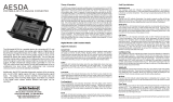
WFM2200
SD/HD/3G SDI Waveform Monitor & Generator
ZZZ
User Manual
*P077066100*
077-0661-00


WFM2200
SD/HD/3G SDI Waveform Monitor & Generator
ZZZ
User Manual
xx
This document supports software version 1.0 and above.
www. tektronix.com
077-0661-00

Copyright © Tektronix. All rights reserved. Licensed software products are owned by Tektronix or its subsidiaries
or suppliers, and are protected by national copyright laws and international treaty provisions.
Tektronix products are covered by U.S. and foreign patents, issued and pending. Information in this publication
supersedes that in all previously published material. Specifications and price change privileges reserved.
TEKTRONIX and TEK are registered trademarks of Tektronix, Inc.
Contacting Tektronix
Tektronix, Inc.
14150 SW Karl Braun D rive
P.O. B o x 5 0 0
Beaverto
n, OR 97077
USA
For product information, sales, service, and technical support:
In North America, call 1-800-833-9200.
Worldwide, visit www.tektronix.com to find contacts in your area.

Warranty
Tektronix warrants t hat this product will be free from defects in materials and workmanship for a period of one (1)
year from the date of shipment. If any such product proves defective during this warranty period, Tektronix, at its
option, either will repair the defective p roduct without charge for parts and labor, or will provide a replacement
in exchange for the defective product. Parts, modules and replacement products used by Tektronix for warranty
work may be n
ew or reconditioned to like new performance. All replaced parts, modules and products become
the property of Tektronix.
In order to o
btain service under this warranty, Customer must notify Tektronix of the defect before the expiration of
the warranty period a nd make suitable arrangements for the performance of service. Customer shall be responsible
for packaging and shipping the defective product to the s ervice center designated by Tektronix, with shipping
charges prepaid. Tektronix shall pay for the return of the product to Customer if the shipment is to a location w ithin
the country in which the Tektronix service center is located. Customer shall be responsible for paying a ll shipping
charges, duties, taxes, and any other charges for products returned to any other locations.
This warranty shall not apply to any defect, failure or damage caused by improper use or improper or inadequate
maintenance and care. Tektronix shall not be obligated to furnish service under this warranty a) to repair damage
result
ing from attempts by personnel other than Tektronix representatives to install, repair or service the product;
b) to repair damage resulting from improper use or connection to incompatible equipment; c) to repair any damage
or malfunction caused by the use of non-Tektronix supplies; or d) to service a product that has been modified or
integrated with other products when the effect of such modification or integration increases the time or difficulty
of servicing the product.
THIS WARRANTY IS GIVEN BY TEKTRONIX WITH RESPECT TO THE PRODUCT IN LIEU OF ANY
OTHER WARRANTIES, EXPRESS OR IMPLIED. TEKTRONIX AND ITS VENDORS DISCLAIM ANY
IMPLIED WARRANTIES OF MERCHANTABILITY OR FITNESS FOR A PARTICULAR PURPOSE.
TEK
TRONIX' RESPONSIBILITY TO REPAIR OR REPLACE DEFECTIVE PRODUCTS IS THE SOLE
AND EXCLUSIVE REMEDY PROVIDED TO THE CUSTOMER FOR BREACH OF THIS WARRANTY.
TEKTRONIX AND ITS VENDORS WILL N OT BE LIABLE FOR ANY INDIRECT, SPECIAL, INCIDENTAL,
OR CONSEQUENTIAL DAMAGES IRRESPECTIVE OF WHETHER TEKTRONIX OR THE VENDOR HAS
ADVANCE NOTICE O F THE POSSIBILITY OF SUCH DAMAGES.
[W2 – 15AUG04]


Table of Contents
General Safety Summary ........................................................................................ vii
Preface .............................................................................................................. ix
Where to find more information............................................................................. ix
Conventions used in this manual............................................................................. x
Getting started.... ........................ .......... .................................. ............................... 1
Product description ............................................................................................ 1
Options and optional accessories............................................................................. 4
Installation...................................................................................................... 6
Configure the network interface............................................................................. 16
Incoming inspection .......................................................................................... 21
Storing or shipping the instrument.......................................................................... 23
Getting acquainted with your instrument ... .............. ................................ .............. ........ 25
Front-panel controls .......................................................................................... 25
Online help .................................................................................................... 29
Instrument display ............................................................................................ 30
Signal inputs and outputs ......................................................................................... 37
Connectors..................................................................................................... 37
Signal inputs................................................................................................... 37
Connector configuration ..................................................................................... 39
Signal outputs ................................................................................................. 40
Display modes ..................................................................................................... 42
ANC Data display (Option DATA only) ................................................................... 43
Arrowhead display............................................................................................ 47
Audio display.................................................................................................. 49
Bowtie display ................................................................................................ 55
Datalist display (Option DATA only)....................................................................... 57
Diagnostics Monitor display................................................................................. 60
Diamond display.............................................................................................. 64
External Reference Waveform display ..................................................................... 66
Generator Status display ..................................................................................... 68
Lightning display ............................................................................................. 71
LTC Waveform display....................................................................................... 74
Picture display................................................................................................. 76
Split Diamond display........................................................................................ 79
Status displays................................................................................................. 81
AES Channel Status display ............................................................................ 82
Alarm Status display..................................................................................... 84
ARIB status displays .................................................................................... 85
Audio Control Packet status display ................................................................... 86
WFM2200 Waveform Monitor & Generator User Manual i

Table of Contents
Audio Session s
tatus display............................................................................ 89
Auxiliary Data Status display....... ................ .......................... ................ .......... 92
Dolby Status display..................................................................................... 94
Error Log status display................................................................................. 96
Video Session status display............................................................................ 99
Timing Measure display ................................................................................... 103
Vector display ............................................................................................... 107
Waveform display........................................................................................... 111
Functions ......................................................................................................... 115
Gain, sweep, and magnification ........................................................................... 115
Measurement cursors (Waveform display only)......................................................... 119
Display capture (freeze).................................................................................... 121
Line select ................................................................................................... 122
Audio volume and source adjustment .................................................................... 124
Presets........................................................................................................ 125
Software upgrades............................................................................................... 131
Before you begin............................................................................................ 131
Software upgrade overview................................................................................ 132
USB software installation.................................................................................. 133
Network software installation ............................................................................. 135
Verify the software and installed options................................................................. 136
Software installation troubleshooting..................................................................... 137
Checking chroma/luma delay .................................................................................. 139
Checking gamut.................................................................................................. 141
To set up gamut checks..................................................................................... 141
Checking RGB gamut...................................................................................... 142
Checking composite gamut................................................................................ 145
Checking luma gamut ...................................................................................... 146
Automating gamut checks ................................................................................. 146
ARIB content displays .......................................................................................... 147
To enable the ARIB content displays..................................................................... 147
ARIB Status display........................................................................................ 148
ARIB STD-B.39 display ................................................................................... 149
ARIB STD-B.37 display and status screens ............................................................. 152
ARIB STD-B.35 display and status screens ............................................................. 155
ARIB TR-B.23 (1) display and status screens........................................................... 157
ARIB TR-B.23 (2) display and status screens........................................................... 159
ARIB TR-B.22 display and status screens ............................................................... 161
Audio monitoring................................................................................................ 163
To configure embedded audio inputs and alarms........................................................ 163
To display an audio input .................................................................................. 164
ii WFM2200 Waveform Monitor&GeneratorUserManual

Table of Contents
To check audio l
evel and phase ........................................................................... 164
To monitor embedded 16-channel audio ................................................................. 167
To check surround sound..... .................. ................................ .................. .......... 168
Closed captioning (CC), teletext, AFD, and safe area compliance......................................... 172
Monitoring CC and teletext................................................................................ 172
Monitoring for safe area compliance ..................................................................... 176
Monitoring
for AFD compliance.......................................................................... 177
Application examples ........................................................................................... 178
Timing a studio.............................................................................................. 178
Troubleshooting cable problems .......................................................................... 183
Index
WFM2200 Waveform Monitor & Generator User Manual iii

Table of Contents
List of Figure
s
Figure 1: Instrument online help................................................................................. 29
Figure 2: Navigate menus using the arrow keys and select button........................................... 31
Figure 3: Display quadrants and related tile numbers ........... ............ ............ ............ .. ..... ... 32
Figure 4: Changing from 4-tile to full-screen view.................. .......... ........................ ........ 33
Figure 5: Thumbnail view in Waveform display............................................................... 34
Figure 6: Elements of the Status bar ............................................................................ 35
Figure 7: Placement of dual link information in the Waveform display..................................... 38
Figure 8: Video signal generation con
nection.................................................................. 40
Figure 9: AES audio signal generation connection............................................................ 41
Figure 10: ANC Data display (full screen mode).............................................................. 43
Figure 11: Arrowhead display ................................................................................... 47
Figure 12: Audio display (Surround mode) .................................................................... 49
Figure 13: Bowtie display ........................................................................................ 55
Figure 14: Datalist display ....................................................................................... 57
Figure 15: Diagnostics Monitor display (page 1).............................................................. 61
Figure 16: Diagnostics Monitor display (page 2).............................................................. 61
Figure 17: Diagnostics Monitor display (page 3).............................................................. 62
Figure 18: Diagnostics Monitor display (page 4).............................................................. 62
Figure 19: Diamond display...................................................................................... 64
Figure 20: External Reference Waveform display (tri-level sync signal) ................................... 66
Figure 21: Generator Status display............................................................................. 68
Figure 22: Construction of the Lightning display.............................................................. 71
Figure 23: Lightning display..................................................................................... 72
Figure 24: LTC Waveform display .............................................................................. 74
Figure 25: Picture display of color bars signal with Safe Area and Picture Center graticules enabled .. 76
Figure 26: Split Diamond display ............................................................................... 79
Figure 27: AES Chan
nel Status display......................................................................... 82
Figure 28: Alarm Status display ................................................................................. 84
Figure 29: Format of the Audio Control Packet ............................................................... 86
Figure 30: Structure of the Audio Control Packet ............................................................. 86
Figure 31: Audio Control Packet status display................................................................ 87
Figure 32: Audio Session status display ........................................................................ 89
Figure 33: Auxiliary Data Status display ........... .................................................... ........ 92
Figure 34: Dolby Status display ................................................................................. 94
Figure 35: Error Log status display ............................................................................. 96
Figure 36: Video Session status display of an HD signal ..................................................... 99
Figure 37: Timing Measure display ........................................................................... 103
Figure 38: Timing display of non-integer multiples of reference rates........ ........................ .... 106
iv WFM2200 Waveform Monitor&GeneratorUserManual

Table of Contents
Figure 39: Vect
or display in Normal mode with the compass rose and I/Q axis graticules enabled ... 107
Figure 40: Vector display in Composite mode ............................................................... 108
Figure 41: Using measurement cursors in the Waveform display.......................................... 120
Figure 42: Navigating line selection .......................................................................... 123
Figure 43: Sample of transfer.exe window after the upgrade is complete ................................ 136
Figure 44: Determining transition intersections in the Lightning display................................. 140
Figure 45: D
iamond display plot .............................................................................. 142
Figure 46: Out-of-gamut examples............................................................................ 143
Figure 47: Arrorwhead gamut display plots.................................................................. 145
Figure 48: ARIB Status display, showing no ARIB data present .......................................... 148
Figure 49: ARIB STD-B.39 display (with the associated ARIB Status display)......................... 149
Figure 50: ARIB STD-B.37 display (with the associated ARIB Status display)......................... 152
Figure 5
1: ARIB STD-B.35 display (with the associated ARIB Status display)......................... 155
Figure 52: ARIB TR-B.23 (1) display (with the associated ARIB Status display) ...................... 157
Figure 53: ARIB TR-B.23 (2) display (with the associated ARIB Status display) ...................... 159
Figure 54: ARIB TR-B.22 display (with the associated ARIB Status display)........................... 161
Figure 55: Audio levels......................................................................................... 165
Figure 56: Checking for phase correlation ................................................................... 166
Figu
re 57: 16-Channel audio bars display .................................................................... 168
Figure 58: Surround sound indicators......................................................................... 169
Figure 59: Auxiliary Data Status display ... .............. .................................................... 174
Figure 60: Closed caption display area ....................................................................... 175
Figure 61: Safe Action and Safe Title areas .............. .................. .................. ................ 177
WFM2200 Waveform Monitor & Generator User Manual v

Table of Contents
List of Tables
Table i: Product documentation.................................................................................. ix
Table 1: Key
features .............................................................................................. 2
Table 2: Instrument options ....................................................................................... 4
Table 3: Optional accessories ..................................................................................... 4
Table 4: Power cord options....................................................................................... 5
Table 5: Service options ........................................................................................... 5
Table 6: Battery charge-level meter icons ...................................................................... 13
vi WFM2200 Waveform Monitor & Generator User Manual

General Safety Summary
General Safet
ySummary
Review the fo
llowing safety precautions to avoid injury and prevent damage to
this product or any products connected to it.
To avoid pot
ential hazards, use this product only as specified.
Only qualified personnel should perform service procedures.
To Avoid Fi
re or Personal
Injury
Use proper
power cord. Use only the power cord specified for this product and
certified for the country of use.
Observe a
ll terminal ratings. To avoid fire or shock hazard, observe all ratings
and markings on the product. Consult the product manual for further ratings
information before making connections to the product.
Do not apply a potential to any terminal, including the common terminal, that
exceeds the maximum rating of that terminal.
Power disconnect. The power cord disconnects the p roduct from the power source.
Do not block the power cord; it must remain accessible to the user at all times.
Do not operate without covers. Do not operate this product with covers or panels
removed.
Do not operate with suspected failures. If you suspect that there is damage to this
product, have it inspected by qualified service personnel.
Avoid exposed circuitry. Do not touch exposed connections and components when
power is present.
Replace batteries properly. Replace batteries only with the specified type and
rating.
Recharge batteries properly. Recharge batteries for the recommended charge cycle
only.
Use proper AC adapter. Use only the AC adapter specified for this product.
D
o not operate in wet/damp conditions.
Do not operate in an explosive atmosphere.
Keep product surfaces clean and dry.
Provide proper ventilation. Refer to the manual's installation instructions for details
on installing the product so it has p roper ventilation.
WFM2200 Waveform Monitor & Generator User Manual vii

General Safety Summary
TermsinThisManual
These terms may
appear in this manual:
WARNING. Warning statements identify conditions or practices that could result
in injury or loss of life.
CAUTION. Caution statements identify conditions or practices that could result in
damage to this product or other property.
Symbols and Terms on the
Product
These terms may appear on the product:
DANGER in
dicates an injury hazard immediately ac cessible as you read
the marking.
WARN ING
indicates an injury hazard not immediately accessible as you
read the marking.
CAUTIO
N indicates a hazard to property including the product.
The following symbol(s) may appear on the product:
viii WFM2200 Waveform Monitor&GeneratorUserManual

Preface
This manual contains the following information to help you use the Tektronix
WFM2200 SD/HD/3G SDI Waveform Monitor & Generator:
How to set up various waveform displays for monitoring SD-SDI, HD-SDI,
and 3 Gb/s SDI video signals.
How to set up audio displays to monitor embedded AES/EBU audio signals.
How to set up parameters for monitoring auxiliary data, ancillary data, closed
captions, and timecode.
How to freeze video data.
How to set up error logging and alarms.
How to operate the instrument remotely.
How to na
vigate instrument menus.
How to operate the instrument front panel.
Where to find more information
This product is shipped with a Product Documentation CD that contains various
user
documents for all users and refere nce information for system integrators. The
following table shows you where you can find this and more information about
your product. You can always find the most updated documentation and software
for your product on the Tektronix Web site at www.tektronix.com/downloads.
Table i: Product documentation
To read about Tektronix part number Use these documents
Installation and safety
071-3018-XX
Installation and Safety Instructions
Pr
ovides installation, safety, general specifications, and
compliance information.
This is a printed manual and is also available on the Web at
w
ww.tektronix.com/downloads.
Instrument operation 077-0661-XX
U
ser Manual (this manual)
In-depth descriptions of instrument operation.
Available on the Web at www.tektronix.com/downloads.
Content-sensitive help topics
NA
Online Help
Detailed instrument operation and UI help is available in your
instrument by pressing the HELP button on the front panel of
the instrument.
WFM2200 Waveform Monitor & Generator User Manual ix

Preface
Table i: Product documentation (cont.)
To read about Tektronix p art number Use these documents
Specifications and procedures for
checking instrument performance
077-0662-XX
Specifications and Performance Verification Technical
Reference
Physical, electrical, and environmental specifications; functional
checks and performance verification procedures.
Available on the Web a t www.tektronix.com/downloads.
Information about declassifying the
instrument
077-0663-XX
Declassification and Security Instructions
Detailed information about how to sanitize the instrument.
Available on the Web a t www.tektronix.com/downloads.
Information about the WFM200BA
battery pack
075-1041-XX WFM200BA Rechargeable Battery Pack Instructions
Provides safety, operating, and recycling information for the
Lithium-Ion battery pack.
This is a printed manual and is also available on the Web at
www.tektronix.com/downloads.
Information about the W FM200BC
battery charger
075-1042-XX
WFM200BC External Battery Charger Instructions
Provides safety and operating information for the optional,
external battery charger.
This is a printed manual and is also available on the Web at
www.tektronix.com/downloads.
Conventions used in this manual
The following icon is used throughout this manual:
Sequence step
or item
x WFM2200 Waveform Monitor & Generator User Manual

Getting started
Your instrument was shipped with a printed Installation and Safety Instructions
manual which includes safety, compliance, and operating requirements along with
power-on, in
stallation, and accessories information. That manual is also available
online at www.tektronix.com/downloads. This User manual contains information
about operating the instrument.
This chapter will help you set up and begin to use the instrument. It is divided
into the following four sections:
Product description describes your instrument and provides a list of key
features.
Options and optional accessories lists the options and optional accessories
which are available for the instrument.
Network installation describes how to set up your instrument for use on an
Ethernet network.
Incoming inspection provides a procedure for verifying the basic operation
and functionality of your instrument.
Product d escription
The WFM2200 SD/HD/3G SDI Waveform Monitor and Generator is a portable
baseband video monitor, offering uncompromised monitoring quality for field
applications with a large 6.5 inch high-brightness, low-power consumption LED
backlit display, and weighing in at less than 4.4 lbs (2 kg).
This instrument provides an array of basic monitoring tools for video (SD, HD,
Dual Link, and optional 3G) and audio (Embedded and AES) signals. You can
co
nfigure the instrument for a full screen or quad-tile display, which allows you to
see all of the necessary signal information at a glance. The ANC Data Inspector,
Data list, and closed caption decode features are invaluable for troubleshooting
problems within the ancillary data space.
You can use the Tektronix patented Timing display and the external reference
waveform display to assist in ensuring correct video timing and troubleshooting
timing problems. The instrument includes a color bar and pathological video
signal generator for troubleshooting signal paths and equipment.
A range of accessories can expand the versatility of the WFM2200 for field
operations such as production setup and troubleshooting. The instrument can
be powered by the supplied rechargeable/replaceable Li-Ion battery pack or the
supplied 100-240 V AC adapter, which provides 19 VDC to the instrument.
WFM2200 Waveform Monitor & Generator User Manual 1

Getting started
Key features
The following k
ey features make this instrument an easy to use, flexible, and
effective tool.
Table 1: Key features
Item Description
Flexible til
edisplays:
Full and Q uad Tile
Quad Tile (4-Tile): View four measurement displays at once, one
in each tile.
In Quad Tile
mode, the high-resolution LED display provides four
concurrent views of a monitored signal (with a maximum of two
trace displays at once). The in strument also provides the flexibility
to con figur
e each of the four display tiles independently, enabling
you to quickly check the integrity of a signal.
Full: View the active display full s creen.
Presets
Customizable presets allow you to quickly save and recall
commonly
used configurations.
Digital support
Support f
or digital applications.
Fully digital
process
ing
Fully Di
gital Processing allows for accurate, repeatable, drift-free
operation that surpasses traditional analog designs.
Video a
nd audio test
signal generation
Multi-
rate color bar and pathological signal generation provides
engineers with a simple signal source for quick signal path
verification during system and/or equipment setup and
troubl
eshooting.
Wavef
orm display
Tradi
tional waveform displays allow signals to be overlaid or
paraded.
Vecto
r display
Vector display with Composite and Component Compass R ose
Graticules, and gain, sweep, and magnification controls. Traditional
and L
ightning Vector displays are available. The latter visualizes
both luma and chroma amplitudes, and quantifies inter-channel
timing.
Infinite Persistence All trace displays can also be set, tile by tile, to Infinite P e rsistence.
Thi
s mode traces waveforms over time on the same display,
providing a visual history of the trace.
Gamut monitoring Arrowhead, Spearhead, Diamond, and Split Diamond displays offer
user-selectable gamut thresholds so that you can set monitoring
li
mits appropriate to a specific operation. Gamut monitoring is fully
integrated with the alarm logging and reporting capabilities.
LTC waveform display Longitudinal Time Code (LTC) is monitored in a frame rate display
to allow observation of amplitude and noise, and verify LT C is
l
ocked to the video.
External Reference
Waveform display
The External Reference waveform display check the external
reference signal integrity, including its shape and amplitude. This
display is independent of the input video signal.
2 WFM2200 Waveform Monitor & Generator User Manual

Getting started
Table 1: Key features (cont.)
Item Description
Surround Sound display of audio signals and phase relationships
of normal channel pairs.
16-channel embedded AES/EBU audio simultaneous monitoring
support with Multichannel Surround Sound
1
display, flex ible
Lissajous display, and two channel AES/EBU BNC input monitoring.
The Lissajous display lets you monitor a user-specified pairing of
channel inputs.
Support and options for viewing and monitoring both levels of
normal channel pairs for embedded audio signals.
Audio monitoring
Support for audio control packet coding and many popular audio
scales, including BBC scales.
Auxiliary data
monitoring
Support for monitoring auxiliary data including data conforming to
ARIB standards and CE A608, CEA708, AFD, and CGMS-A.
Timing display
A Tektronix proprietary display that simplifies measuring the timing
difference between two signals. Using the Timing display enables
you to easily compare and correct the timing between two signals.
Closed Captioning
support (Option DATA
only)
Support for simultaneous decode and display in multiple languages
of CC standards (CEA 608 (V BI), CEA 608 (ANC), CEA (608/708),
CEA 708, TeletextB (VBI), TeletextB OP47 SDP (ANC), and
TeletextB OP47 Multi (ANC)) w ith caption text and V-chip
information overlaid on the picture (monitor mode). There are also
settings for missing or incorrectly inserted closed captioning.
Picture area
Support for standard and custom Safe Graticules for Picture
displays that look for incorrect placements of graphics, logos, Black
events, and Frozen events. Two Safe Area graticules and Safe
Title graticules are supported.
Status screens Status screens provide content status at a glance.
Error tracking
Configurable alarms and error logging.
Remote control
Full remote control for complete installation flexibility.
Data List display
Examines the contents of all digital formats, structures, and
transports and displays the data without any interpolation.
Ancillary data
inspector
Allows you to monitor all ancillary data present in a signal.
1
Audio Surround Sound Display licensed from Radio Technische Werksütten GmbH and Co. KG (RTW).
WFM2200 Waveform Monitor & Generator User Manual 3

Getting started
Options a nd op
tional accessories
Your instrument may have been ordered with one or more of the options listed in
this section.
Instrument o
ptions
The following options are available for the instrument:
Table 2: Instrument options
Option Description
3G Adds support for 3G-SDI (Level A and Level B) signal formats.
DATA Adds comp
rehensive data monitoring, which helps to quickly resolve
difficult content quality and reliability issues through closed captioning,
subtitles, AFD decode/display and full ANC data s upport.
Check the installed options.
When th
e instrument is powered on, you can check which options are installed on
your instrument by performing the following steps:
1. Press t
he CONFIG button on the front panel.
2. Use the General knob to navigate to Utilities.
3. Press the right arrow button to navigate to the Utilities submenu and select
View Instrument Options. The menu box on the right side of the display
show
s the installed options.
Optional accessories
You can purchase any of t he following accessories for your instrument.
Table 3: Optional accessories
Accessory Description
WFM200BA Additional Li-Ion rechargeable battery pack. The instrument is shipped
with one WFM200BA rechargeable battery pack.
WFM200BC External battery charger for the WFM200BA rechargeable battery pack.
WFM200FSC Soft carrying case to protect the instrument with room for the instrument,
AC adapter, and battery pack(s).
4 WFM2200 Waveform Monitor & Generator User Manual
/