Alto Aqua Leader Contempra General Instructions Manual
- Category
- Above ground pools
- Type
- General Instructions Manual


TABLE OF CONTENTS
GENERAL INSTRUCTIONS - OVAL POOLS
SECTION
PARTS
LISTING
SECTION
ASSEMBLING
THE POOL BASE
SECTION
GROUND
PREPARATION
SECTION
ASSEMBLING
THE POOL WALL
SECTION
INSTALLING
THE LINER
1
2
SECTION
ASSEMBLING
THE POOL FRAME
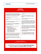
ABOVE GROUND POOL SAFETY
PLEASE READ BEFORE INSTALLATION
FAILURE TO HEED THESE WARNINGS CAN RESULT IN PERMANENT INJURY, PARALYSIS FROM
A BROKEN NECK, ELECTROCUTION OR DROWNING. THIS POOL IS NOT DESIGNED FOR DIVING
OR JUMPING! DANGEROUS INJURY CAN RESULT, SHALLOW WATER!
Your pool contains a large quantity of water, and is deep enough to present inherent dangers to life and health unless the
follow¬ing safety rules are strictly observed. First-time users run the highest risk of injury. Make sure everyone under-
stands. To insure your pool is used safely you must observe the following safety precautions:
1. NO JUMPING OR DIVING
The top rail of your pool is not a walkway and must not be used for jump-
ing or diving. Do not permit jumping or diving into the pool from a deck or
the top rail of the pool. Diving or jumping into the pool can result in serious
injury.
2. NEVER USE THE POOL ALONE
Never permit the pool to be used unless it is attended by at least one
person other than the bather. Someone should always be available to lend
assistance in an emergency.
3. NEVER LEAVE CHILDREN UNATTENDED
Never leave a child alone and unsupervised in or near the pool—not even
for a second. There is no substitute for constant adult supervision.
4. NO ROUGH PLAY
Do not permit “rough-playin” in and around your pool. Surfaces can become
slippery and hazardous when wet.
5. LIGHT THE POOL AT NIGHT
If the pool is used after dusk, adequate lighting must be provided. Illumina-
tion in the pool area must be sucient to clearly judge pool depth and all
features in and around the pool. For light¬ing recommendations, consult
your local licensed electrical contractor
6. RESTRICT ACCESS TO THE POOL
Do not leave chairs or other furniture beside the pool that could be used by
a child to climb up into the pool. Ladders must be removed whenever the
pool is unattended. A fence with a lockable gate around the pool or yard is
strongly recommended and may be required by law in some jurisdictions.
7. NO ALCOHOL OR DRUGS
Never drink alcoholic beverages or use any intoxicants which could hinder
your judgment and reexes.
8. KEEP YOUR POOL CLEAN AND SANITARY
Your lter system will remove suspended particles from the water and the
surface skimmer will remove insects, leaves and other debris from the wa-
ter surface. Use the correct pool chemicals as directed to destroy harmful
bacteria and prevent formation of algae. Remember, unsanitary water is a
serious health hazard.
9. KEEP OFF TOP LEDGES
Do not walk on top ledges. They can be slippery and they are not a walk-
way.
10. POOL COVER SAFETY
The cover must have a tamperproof locking retainer cable that positions
the cover around the pool wall and keeps it securely in place. Never allow
anyone, especially small children on the cover. Asphyxiation or drowning
could result. When purchasing any pool cover, please consult a swimming
pool professional.
11. ELECTRICAL HAZARD
Never touch or attempt to service electrical equipment, including the lter
when your body and/ or the ground is wet. Electrocution or permanent
injury due to high voltage (120V AC) could result. The pool should be
bonded in accordance with Section 680-26 of the National Electical Code.
For further assistance contact your dealer or a local licensed electrician.
Do not use pool during electrical or rain storms.
12. SAFETY ROPE & POLE
Keep a safety rope 1/4” by 50” with a otation buoy with an outside
diamter of 15”. Have ac¬cessible in a prominent area by your pool. Keep a
pole not less that 16 feet (4,88m) long with a blunt or hook end available
at pool side in case of emergencies.
13. POOL CHEMICALS
Do not place chlorine, chlorine tablets or sticks directly into skimmer, or
winterize your pool with liquid chlorine. Damage to the skimmer, pool liner
and lter will result. Failure to obey this in¬struction will void all compo-
nent warranties. Always follow Chemical Manufacturer’s insturctions when
storing, handling and dispensing pool chemicals.
14. CHECK FOR DAMAGE
Periodically check your pool and ladder components for damage and wear.
Be sure all screws are in place. Replace all damaged or worn components
and tighten all screws before you use the pool, deck or ladders. At rst
sign remove rust and touch up immediately.
15. POOL PARTS
Never modify the pool or accessories, or remove or drill holes in the pool,
deck or ladder com¬ponents unless instructed. Your pool wall is made of
thin metal, there is an inherent cut hazard with metal so use gloves during
installation. Always use Original Equipment Manufactured parts
FOLLOW ALL SAFETY INSTRUCTIONS
Read and follow all safety instructions packaged with pool, ladder, deck or any other accessory. Additional pool safety publications can be
obtained by contacting: The Association of Pool & Spa Professionals (www.apsp.org)
Important notice read before installation!
The safety stickers must be installed as per following instructions. Failure to properly install warning labels will void warranty. Failure
to mount these safety labels may subject you to substantial liability in case of injury. These warning are not to be removed under any
circumstances! If they become discolored or fall o please request replacements which will be sent at no charge.
01
03
02
04
05
06

01
SECTION
GENERAL INSTRUCTIONS - OVAL POOLS
Index Description
Part # 15x26 15x30 18x33 18x40 21x43
Ledge cover top
Ledge cover inner
Ledge cover outer
Top plate
Inner upright
38626
38625
38624
38594
A
B
C
D
E
18
18
18
18
20
20
20
20
22
22
22
22
26
26
26
26
26
26
26
26
Parts listing
PARTS
LISTING
4
3
01
SECTION
GENERAL INSTRUCTIONS - OVAL POOLS
Exploded view
PARTS
LISTING
Refer to page 6
Inner upright_ 52’’ Tall
Inner upright_ 54’’ Tall
38590
38591
18
18
20
20
22
22
26
26
26
26
F
H
J
G
K
I
Top ledge clip
Outer upright
Boot
Outer upright clip
Steel wall
Top ledge spacer
Top rail clip _ round section
Top rail clip _ straight section
Outer upright_ 52’’ Tall
Outer upright_ 54’’ Tall
Boot _ round section
Boot _ straight section
38592
22090
38588
38589
38627
22902
WCRS52/54
38593
38787
16
2
18
18
12
6
18
1
12
16
4
20
20
12
8
20
1
12
18
4
22
22
14
8
22
1
14
18
8
26
26
14
12
26
1
14
16
10
26
26
12
14
26
1
-
A
B
C
D
E
F
G
H
F
K
J
I
L
M
N
J

Bottom rail _ straight section 9’0’’ R 37-1/2’’
Bottom rail _ round section 7’6’’ R 49’’
Bottom rail _ round section 9’0’’ R 50’’
Bottom rail _ round section 10’6’’ R 54-7/16’’
Bottom rail _ transition section 9’0’’ R 39’’
Bottom rail _ transition section 10’6’’ R 53-1/2’’
Stabilizer _ straight section 33’’
Stabilizer _ round section 7’6”R 53-1/4”
Stabilizer _ round section 9’0”R 54-1/8”
Stabilizer _ round section 10’6”R 54-7/16”
Stabilizer _ transition section
Straight side stabilizer at the straight
side upright
Stabilizer
01
SECTION
GENERAL INSTRUCTIONS - OVAL POOLS
Index Description
Part # 15x26 15x30 18x33 18x40 21x43
16713
38502
38503
38505
16714
26097
38512
38502
38503
38505
38511
38513
4
10
-
-
4
-
4
10
-
-
4
6
6
10
-
-
4
-
6
10
-
-
4
8
6
-
12
-
4
-
6
-
12
-
4
8
10
-
12
-
4
-
10
-
12
-
4
12
12
-
-
12
-
4
12
-
-
12
-
14
Parts listing
PARTS
LISTING
6
L
N
-
-
M
01
SECTION
GENERAL INSTRUCTIONS - OVAL POOLS
Index Description
Top Ledge Bottom Rail
Part # 15x26 15x30 18x33 18x40 21x43
Top ledge _ straight section 41’’
Top ledge _ round section 15’ 49-1/2’’
Top ledge _ round section 18’ 51-1/8’’
Top ledge _ round section 21’ 55-1/8’’
Skimmer Top Ledge 15’ 49-1/2’’
Skimmer Top Ledge 18’ 51-1/8’’
Skimmer Top Ledge 21’ 55-1/8’’
22809
22104
22106
22108
22105
22107
22109
8
9
-
-
1
-
-
10
9
-
-
1
-
-
10
-
11
-
-
1
-
14
-
11
-
-
1
-
12
-
-
13
-
-
1
Parts listing
PARTS
LISTING
5
Flat cooping 48’’
Wall hardware
10206
10607
18
1
20
1
22
1
26
1
28
1
- Wall joiner bar
Wall joiner bar 52’’
Wall joiner bar 57’’
# 10 TEK
# 12X1
# 12 PTD
37397
37398
99-0090
99-0085
99-0127
2
2
216
126
18
2
2
240
140
20
2
2
264
154
22
2
2
312
182
26
2
2
312
182
26

Key Description
02
SECTION
GENERAL INSTRUCTIONS - OVAL POOLS
GROUND
PREPARATION
Base U-Channel
Upright Channel
Inside ‘L’ Bracket
Middle ‘T’ Bracket
Outside ‘T’ Bracket
Hold Down Plate (Pressure plate)
Strap Bracket
Strap
Hardware bag, 1per set of buttresses;
(Refer to page 8)
1/4’’ -20NCx3/4’’ hex bolt
1/4’’ -20NCx3/4’’ serrated ange hex nut
3/8’’-16NCx1’’ hex bolt
3/8’’-16NC serrated ange hex nut
No. 12x5/8’’ self-tapping screw
1/4’’-20NC nut clip
7
1
4
3
2
11
30
8
-
9
10
5
6
12
24
8
Parts listing _ Buttress assembly
Part # 15x26 15x30 18x33 18x40 21x43
1440335
1440383
1320147
1320138
1320139
1320166
1320164
1184293
1184275
1184052
1184237
1184238
1184105
1184278
6
6
12
12
12
12
6
3
72
48
216
216
24
24
8
8
16
16
16
16
8
4
96
64
288
288
32
32
8
8
16
16
16
16
8
4
96
64
288
288
32
32
12
12
24
24
24
24
12
6
144
96
432
432
48
48
14
14
24
24
24
24
14
7
196
140
504
504
56
56
02
SECTION
GENERAL INSTRUCTIONS - OVAL POOLS
GROUND
PREPARATION
Overview of the Buttress assembly
7
Inside of Pool
12
11
12
11
9
9
8
8
10
10
30
24
24
1
5
5
2
2
3
3
6
6
4
4
13
13
7
5
Strap 15’
Strap 18’
Strap 21’
Strap Hardware
1510140
1510141
1510142
22098
9
-
-
-
12
-
-
-
-
12
-
-
-
18
-
-
-
-
28
1

02
SECTION
GENERAL INSTRUCTIONS - OVAL POOLS
GROUND
PREPARATION
Hardware for gibraltar pools
109

Check local laws on construction and electrical installation. Also make sure
that you meet security standards related to fences and pool cover. Select an ap-
propriate site for your swimming pool by considering the following points:
GENERAL INSTRUCTIONS - OVAL POOLS
Plan your installation rst
Distance from the fence
Overhead electrical wires
Predominant winds
Accessory location (lter,
decking, …)
Appropriate electrical outlets
Surrounding trees (falling leaves
and roots)
Underground cables and gas con-
ducts
Do not install your pool on concrete,
asphalt, wood, grass turf, top of grass,
gravel or chemically treated soil. Avoid
also weed and nut grass area.
Avoid areas with poor drainage.
Do not install on windy days
Sun reection in your yard
Install with 2 or 3 helpers
+
+
+
+
+
+
+
+
+
+
+
Be careful
Ground surface and levelness: it is very important that the ground surface be rm
and solid. Pool area must be free of grass, rocks roots or other sharp edges objects.
Any parcel of grass left under the pool will rot and release unpleasant odors. Avoid
installing your pool on surface which has been treated with oil weed-killer or chemical
products. This could aect the vinyl liner among other things.
The entire pool surface must be completely levelled when preparing your site.
DO NOT FILL LOWER GROUND AREA because any added ground won’t give the
needed strength to support pools weight. For a surface level delta greater than
3 ‘’ (10 cm), contact your pool supplier for specic instructions relative to your
situation.
Before you start your installation: make sure you have all the parts for complete
assembling (see your parts lists). If irregularities such as missing part(s) or defect(s)
ever occur, go to your dealer to get new pieces.
< 3’’ MAX
X
SPECIAL
NOTICE WILL
BE DELIVERED
BY YOUR
LOCAL DEALER
FOR EVERY
INSTALLATION
OUT OF THE
MANUFACTURER
STANDARDS.
PREPARATION
+
02
SECTION
GENERAL INSTRUCTIONS - OVAL POOLS
1. The Terrain
Pay special attention to choosing the right location for your
pool:
• Choose a large area, as at and level as possible and well
drained. (Image 2.1)
• Choose a spot on dry, rm earth (stabilizer or other)—do not
install the pool on asphalt, tar or oil based surfaces, gravel, peat
moss, wood or chemically treated soil.
• Check with your pool dealer to see if Nut Grass grows in your
area. This type of grass may grow up through your pool liner.
Your dealer will be able to advise how best to treat the site.
• Sloped areas will need to be made level by digging away high
spots, not by lling low spots—be prepared to hire earth-moving
equipment if necessary. (Images 2.21 & 2.24)
• Ensure the earth is well compacted and a wall is placed to
prevent the earth from seeping out. (Image 2.21)
• If you need to install partly in the ground, you must contact
your dealer to see if this is an option for you and that you meet
law requirements in your jurisdiction. (Image 2.24)
Ground preparation is one of the most important steps in the
installation process. A proper foundation will ensure the rest
of the pool assembly goes smoothly and that no problems will
occur when the pool is lled with water.
GROUND
PREPARATION
2.2.1
A. DETERMINE THE LOCATION OF YOUR POOL
2.1
2.2.3
2.2.4
IMPORTANT NOTE:
11 12

13
02
SECTION
GENERAL INSTRUCTIONS - OVAL POOLS
GROUND
PREPARATION
2. Things to Avoid
3. Plan Ahead
Do not locate your pool near or on any of the following
(Images 2.3.1 to 2.3.3) :
• Overhanging tree branches.
• Overhead wires and clotheslines.
• Buried pipes and wires. Contact your gas, electric and tel-
ephone utilities to nd buried pipes and wires before you dig.
• Areas with poor drainage.
• Grass, stones and roots. Grass will rot underneath the pool
liner, and stones and roots will damage the pool liner.
• Areas recently treated with oil-based weed killers, chemicals
or fertilizers.
• Will you be adding an adjacent deck later? Be sure to leave
room.
• Will you be using pool accessories or other appliances that
need electricity or gas? Locate your pool near these services
or plan to have them installed later by a licensed contractor.
When locating the centre of the pool, be sure to take into
consideration any structures (deck, patio, house) or relevant
items (change rooms, gazebo, etc.) that the pool may need
to line up with and ensure that the pool is in the most visual
pleasing location for your property.
2.3.1
2.3.2
2.3.3
IMPORTANT NOTE:
02
SECTION
GENERAL INSTRUCTIONS - OVAL POOLS
GROUND
PREPARATION
14
4. Tools Needed
List of required materials
• Straight wood plank
• Material that provides a permanent base (ex. Crushed stone)
• Fine sand (void of debris)
• Cement blocks (5cm x 20cm x 40cm / 2”x 8”x16”) (optional)
• 2x Plywood (60cm x 120cm /2ft x 4ft)
• Wood board (30cm x 20cm / 1ft x 1ft)
• Vinyl covered hooks (to hold wall steady)
• String and stakes & wooden pegs
• Prefabricated cove sections (optional)
• Pool carpeting (optional)
• Rope
• Polyethlyne Plastic Sheeting
• Optical Level can be useful for precise measurements

15
02
SECTION
GENERAL INSTRUCTIONS - OVAL POOLS
GROUND
PREPARATION
1. Mark out the Area
a) The next following steps will show you how to mark out the
area you need for the oval pool. This marked area will be larger
than the pool size itself, but this space is needed. Find a site
where the ground is stable, level and well drained. Once you
have selected your site, determine where the middle of your
pool will be.
b) Drive a peg into the ground at the centre point. (Image 2.4)
c) Now you must make the round ends that will be the oval
part. In order to do so, you will have to determine the center
of the radius on each side and drive a peg into the ground.
(Image 2.5)
d) Using a length of string tied between the peg and a can of
spray paint mark the circles on the ground. (Image 2.6)
e) Once the center has been established, and the measurement
of the pool itself has been determinded, you must now deter-
mine the outer limits of the perimeter of your pool. Add 12”
(30 cm) outside this measurement to determine pool perimeter.
(Image 2.7)
B. PREPARE THE FOUNDATION OF YOUR POOL
See Diagrams:
Please see in the next page for an EXAMPLE p.11 on how
to correctly mark your pool area. Please verify your pool’s
FOOTPRINT for correct measurements on page 57.
2.4
2.5
2.6
2.7
Determine the center of the pool
Determine radius center on each side
Trace radius on each side
Determine outer limits of the pool
Radius Radius
02
SECTION
GENERAL INSTRUCTIONS - OVAL POOLS
GROUND
PREPARATION
16
2. Remove the sod
f) Mark areas along both straight sides of your oval. Use pegs
and string as a guide for the can of spray paint to mark straight
lines. (Image 2.8)
g) You now have the space marked out that is needed for your
oval pool. (Image 2.9)
a) Remove the sod from the area you have just outlined. (Image
2.10)
b) Remove all debris (rocks, roots, etc) using a rake. Then com-
pact the ground to achieve a rm base. You can use a sod re-
moval machine.
Your pool must be perfectly level. Take the time you need to
be sure your foundation is perfecty level.
2.8
2.9
2.10
IMPORTANT NOTE:
Trace rectangle
Space needed for pool

17
02
SECTION
GENERAL INSTRUCTIONS - OVAL POOLS
GROUND
PREPARATION
Example on how to mark out pool area for an 18 x 33
Please be sure to use your pool’s footprint for your pool size on page 57.
EXAMPLE
02
SECTION
GENERAL INSTRUCTIONS - OVAL POOLS
GROUND
PREPARATION
18
3. Make the area at and level
a) Remove all the high spots with a shovel, hoe or rake. To make
sure your pool is stable, compact the ground well before adding
the sand. Be prepared to hire earth moving equipment if you
need to level a large area. Remember, your pool must be level
across the diameter of the pool. (Image 2.11)
b) Small dips and hollows may be lled in, but the soil must be
hard-packed with a tamping tool or a soil compactor.
c) Take material such as rock dust or ne mortar that can con-
form a solid, permanent base and deposit this material around
the rim of the basin. (Image 2.12)
d) The material used should be spread around the perimeter of
the pool to a width of 24” (60cm) and a thickness of 2” (5cm).
(Image 2.13)
e) Recheck the outer perimeter of the oval shape, where the pool
wall will be placed. Compact the ground and make sure there are
no high or low spots. The bottom edge of the pool wall must rest
at on the ground and have no gaps under it.
Your pool must be perfectly level. Take the time you need to
be sure your foundation is perfecty level.
IMPORTANT NOTE:
2.11
2.12
2.13
Level
396 (33 FT.)
42
16
27
15
52
136
219
218
(18 FT. 2 IN.)
Strap
57
1
4
(12 Places)
252
252
223
R108
57.2375
57.2375
57.2375
57.2375
57.237557.2375
57.2375
57.2375
57.2375
57.2375
57.237557.2375

02
SECTION
GENERAL INSTRUCTIONS - OVAL POOLS
GROUND
PREPARATION
4. Measuring for the buttress trenches
a) In order to measure where trenches need to be dug for the
placement of the buttress, you must rst draw a perpendicu-
lar line in order to create a perfect 90 degree angle. From the
pool center, trace a straight line to the oval perimeter. (Image
2.14)
b) In order to ensure that your line is perpendicular, measure
from each radius center to the top of your line. The measure-
ment should be exactly the same on each side. If not, adjust
until both are the same and you will now have a perfect per-
pendicular line, therfore creating a perfect 90 degree angle.
(Images 2.15 & 2.16)
c) Repeat the rst two steps to create a perpendicular line in
order to create a perfect 90 degree angle for the other side
of the oval pool.
It is very important that when you follow the instructions on
the next page, that you apply the next steps to only one side
of the pool at a time. It is imperative that you follow the next
steps in order.
IMPORTANT NOTE:
2.14
2.15
2.16
C. GROUND PREPARATION FOR THE BUTTRESS
19
02
SECTION
GENERAL INSTRUCTIONS - OVAL POOLS
GROUND
PREPARATION
5. Digging the buttress trenches
Odd number of trenches :
Even number of buttresses :
a) If your oval pool contains an even number of buttresses,
please proceed with next step b. If your oval pool contains an
odd number, position the buttress temporarily on the straight
center line from the middle. (Image 2.17)
Continue to step c. Note: Odd number means the total of sec-
tions on one side, for example a 12 x 24 pool has Odd number.
b) If your oval pool contains an even number of buttresses,
measure from the center line out the required measurement as
per your footprint, see the last pages in this section 1. Posi-
tion the buttress temporarily o the straight ceter line from the
middle. (Image 2.18) Continue to step c. Note: Even number
means the total of sections on
one side, for example a 15 x 30 pool has Even number.
c) Carefully dig out the trench. DO NOT dig the trenches too
large or too deep; the ground around the edges of each trench
must remain rm and undisturbed. (Image 2.19)
This rst buttress that you install will be the reference to
install the remaining butresses, therefore ensure that
measurments and placements are exactly where they need
to be. VERIFY YOUR POOL’S FOOTPRINT!
IMPORTANT NOTE:
See your pool’s
footprint for correct
measurement
2.17
2.18
2.19
20
Concrete
patio stone
6" (15 cm)
5 1/2" (14 cm)
36" (91 cm)
4" (10 cm ) to face
of patio stone
20" (51 cm)
20" (51 cm)
Painted centreline
of trench
Pool Wall Line:
(N.B. the pool wall
will lie on this line)

02
SECTION
GENERAL INSTRUCTIONS - OVAL POOLS
GROUND
PREPARATION
d) The bottom plates for the straight section must be at the
same level with the crushed stone. Spread a layer of crushed
limestone (or equivalent) 3/4” (19 mm) thick into the bottom
of each trench. Pack rmly. If you do not put crushed stone,
understand that the bottom plates all around the pool must
be at the same level. The warranty will void if you do not
comply with this requirement.
e) Place a concrete patio stone 12” x 12” square x 2” thick
(30 x 30 x 5 cm) into the wide part of each trench, on top of
the limestone layer. Make sure it is LEVEL and positioned
correctly. (Images 2.20 & 2.21)
Crushed limestone or equivalent must be used instead of
brick sand or vermiculite to backll the base U-channels. The
level of compaction achieved by using crushed limestone or
equivalent is superior to that of brick sand or vermiculite.
IMPORTANT NOTE:
2.20
2.21
21
Concrete patio
stone
Concrete patio
stone
Trench
Crushed limestone (or equivalent) base
3/4" (19mm) in bottom of trench
02
SECTION
GENERAL INSTRUCTIONS - OVAL POOLS
GROUND
PREPARATION
2.22
2.23
6. Assemble Buttresses for Base Channels
a) Add another layer of crushed limestone (or equivalent) 1”
(25mm) thick into the bottom of each trench, and around the
patio stones. Pack rmly. (Image 2.22)
b) In each trench, measure 32” (81 cm) from the Pool Wall Line
to the end of the channel. Carefully add more limestone (or
equivalent) to the trench. (Image 2.23)
c) Repeat steps 5 (a) or (b), depending if you have odd or
even number of trenches up to step 6 (b)for the rest of the
base U-channels and trenches. Remember to please follow
your pool’s footprint at the end of this Section 1 for meas-
urements on the placement of the
trenches.
d) Use the carpenter’s level to make sure everything is exactly
level with the rest of the cleared area and the base plates (the
base plates will be installed in Section 2). If it is not, the base U-
channel must be removed and the crushed limestone (or equiva-
lent) and patio stone adjusted.
This rst buttress that you install will be the reference to
install the remaining butresses, therefore ensure that
measurments and placements are exactly where they need
to be. VERIFY YOUR POOL’S FOOTPRINT!
Make sure there is adequate drainage in the bottom of each
trench and along the sides of the pool area. There must be
adequate drainage for a safe and secure pool foundation.
IMPORTANT NOTE:
CAUTION:
22
Additional crushed
limestone (or equivalent)
layer 1" (25 mm) thick
AA
ool all ine
( the ool
all ill lie on this line)
2" (1 cm)
" (1 cm)
Additional crushed
limestone (or equivalent)
32’’

02
SECTION
GENERAL INSTRUCTIONS - OVAL POOLS
GROUND
PREPARATION
Overview of the Buttress assembly
23
Inside of Pool
12
11
12
11
9
9
8
8
10
10
30
24
24
1
5
5
2
2
3
3
6
6
4
4
13
13
7
5
02
SECTION
GENERAL INSTRUCTIONS - OVAL POOLS
GROUND
PREPARATION
KEY PART NAME
Base U-Channel
Upright Channel
Inside ‘L’ Bracket
Middle ‘T’ Bracket
Outside ‘T’ Bracket
Hold Down Plate (Pressure plate)
Strap
Strap Bracket
Hardware bag, 1per set of buttresses; includes;
1/4’’ -20NCx3/4’’ hex bolt
1/4’’ -20NCx3/4’’ serrated ange hex nut
3/8’’-16NCx1’’ hex bolt
3/8’’-16NC serrated ange hex nut
No. 12x5/8’’ self-tapping screw
1/4’’-20NC nut clip
7
1
4
3
2
11
8
30
-
9
10
5
6
12
24
24

02
SECTION
GENERAL INSTRUCTIONS - OVAL POOLS
GROUND
PREPARATION
Hardware for gibraltar pools
25
02
SECTION
GENERAL INSTRUCTIONS - OVAL POOLS
GROUND
PREPARATION
1. Assembling the Buttresses (Straight Section)
a) Assemble one upright channel (key 1) with two T-plates (key 2 and 3) and
one L-plate (key 4) (one each of sizes short, medium and tall) on one side using
eight bolts (key 5) and nuts (key 6). The bolt heads should be on the outside of
the T- and L-plates and the nuts on the inside of the upright channel. Do not
tighten the bolts yet. Be sure to
follow the drawing carefully to have the T- and L-plates and upright channel
facing the right direction (the T-plates each have a radiused corner; this radi-
used corner must FACE AWAY from the open side of the
upright channel). (Image 2.27)
b) Repeat step (a) for the other side of the upright channel with three more
T- and L-plates.
c) Insert the upright channel and T- and L-plate assembly into a base U-chan-
nel (key 7). The open side of the upright channel will face toward the inside of
the pool. Line up the holes and fasten with twenty bolts (key 5) and nuts (key
6). Do not tighten the bolts yet. (Image 2.28)
d) First, tighten the eight bolts and nuts on each side of the
upright channel. Second, tighten the four bolts and nuts on
each side of the base U-channel. Lastly, tighten all the rest
of the bolts and nuts (see image 2.27 and 2.28).
Important: for a proper t, you must push the T- and L-
plates against the upright channel while tightening the bolts
and nuts (image 2.28).
D. ASSEMBLING THE BUTTRESS
Lift the base U-channel out of the trench rst to
fasten it to the vertical U-channel and T-plates.
Failure to properly install and tighten all of the bolts
and nuts may void the warranty on your pool.
IMPORTANT NOTE:
IMPORTANT NOTE:
Radiussed
corner
6
1
5
4
3
2
7
6
5
Tighten these eight bolts first on
each side of the upright channel
Tighten these four bolts second on each
side of the base of the U-Channel
Tighten these six bolts last on
each side of the base of the
U-Channel
Push L and T plates
against the upright
channel while tighten-
ing the bolts
2.27
2.28
26

02
SECTION
GENERAL INSTRUCTIONS - OVAL POOLS
GROUND
PREPARATION
27
When measuring the distance to the face of each base plate, use
a piece of string longer than required and place a mark on the
string at the required distance.
IMPORTANT NOTE :
a) Insert the bottom plate by slidding it on each upright chanel
b) Insert the buttress rails between the buttresses, the bottom rails
insert into the bottom plate. Make sure the groove faces up.
c) Insert the transition rails. Slide one end of each rail into the bot-
tom plate in the upright channel and slide the other end together
with a bottom plate.
2.29
2.30
E
E
J
J
2.31
13
2. Insert the buttress (Straight Section)
02
SECTION
GENERAL INSTRUCTIONS - OVAL POOLS
GROUND
PREPARATION
a) Fill the base U-channels and the trenches they sit in with
crushed limestone (or equivalent). Fill them up to the top edges
of the base U-channels. If the limestone is dry spray it with some
water to help with the compaction. Stand on the base U-channel
and tamp down the limestone until a solid base is achieved (by
standing on the base U-channel your weight helps prevent the base
U-channel from moving). Add additional limestone as required. (Im-
age 2.32)
b) Make sure the space under the end of the base U-channel is com-
pletely lled with crushed limestone. (Image 2.33)
c) Recheck the distances between the base U-channels and make
any adjustments you need to make sure the spacing is exactly right.
Crushed limestone or equivalent must be used instead of
brick sand or vermiculite to backll the base U-channels. The
level of compaction achieved by using crushed limestone or
equivalent is superior to that of brick sand or vermiculite.
IMPORTANT NOTE:
28
2.32
2.33
3. Fill the Base U-Channels (Straight Section)
Make sure the space under the end of
the base U-Channel is completely filled
with crushed limestone (or equivalent)
hard-packed
crushed
limestone
base
U-Channel

22" (55cm) 22" (55cm)
Stand on the
base U-Channel
Use a hold down plate to drag
the area to either side of the
base U-Channel, smooth and level
02
SECTION
GENERAL INSTRUCTIONS - OVAL POOLS
GROUND
PREPARATION
4. Install Straps, Strap Brackets and Hold Down Plates (Straight Section)
a) Gently atten any kinks or bends out of the straps.
b) Dig out the area between and to the sides of the base
U-channels, down to a level exactly even with the tops of each
base U-channel and 22” (55 cm) beyond the sides of each base
U-channel. (Image 2.34)
c) Dig a shallow trench, 3” (8 cm) wide and approximately1-1/2”
(4 cm) deep for each strap (make the trench as deep as the
top of the base U-channel), aligned with the centreline of the
trench, from one side of the pool to the other.
d) Using a straight edge (you can use one of the hold down
plates), drag along the top edge of the base channel to ensure
the ground is level to the base U-channel. If it is not level,
spread some crushed limestone on the ground. Stand on the
base U-channel and tamp it down hard with a tamping tool.
Verify the ground is level to the base U-channel by running the
straight edge along the top edge of the base U-channel again.
Repeat this step until the ground is level. (Image 2.35)
e) Slide four nut-clips (key 24) onto one end of the base chan-
nel assembly (Image 2.36) so they line up over the holes in
the base channel. The threaded parts of the nutclips should
point down.
Brick sand or vermiculite cannot be used on any part of the but-
tress installation process. These materials have poor compaction
properties that can cause problems with the buttresses after the
pool has been lled with water
IMPORTANT NOTE :
29
2.34
2.35
2.36
9
24
7
02
SECTION
GENERAL INSTRUCTIONS - OVAL POOLS
GROUND
PREPARATION
f) Join one end of a strap (key 8) to a strap bracket (key 30). The
strap should be on top of the strap bracket. Line up the holes (be
sure to use the holes shown in Image 10) and fasten together
with four hex head bolts (key 9) and four nuts (key 10). The bolt
heads must be on the top and the nuts underneath. Tighten the
bolts. (Image 2.37)
g) Line up the holes in the strap bracket (be sure to use the
holes shown in Image 2.38) with the nut clips (key 24) at the
end of the base U-channel (key 7) and fasten together with
four hex head bolts (key 9) Tighten the bolts snuggly but do not
overtighten.
h) Repeat steps (d to g) for the corresponding strap and strap
bracket on the opposite side of the pool.
Failure to properly compact this material may result in the
crushed limestone being compacted instead by the weight of
the water after the pool is lled, resulting in indentations in the
bottom of the pool.
IMPORTANT NOTE:
30
2.37
2.38
8
9
10
30

02
SECTION
GENERAL INSTRUCTIONS - OVAL POOLS
GROUND
PREPARATION
i) Spread 3/4” (19 mm) of crushed limestone (or equivalent) over the dug
out area for the hold down plate closest to the centre of the pool. Do not
spread any material over the top of the base U-channel. Place the hold
down plate as shown in Image 2.39 on top of the crushed limestone.
Make sure each entire hold down plate lies completely
at in the area dug out explained in previous step 3 (d).
The hold down plate must lie at or it may lift and damage
the pool liner after the pool is lled with water. (Image 34)
IMPORTANT NOTE :
31
2.39
2.40
11
Shift the hold down plate
back and forth to make it settle
7
11
11
02
SECTION
GENERAL INSTRUCTIONS - OVAL POOLS
GROUND
PREPARATION
j) Begin shifting the hold down plate in a forwards
and backwards motion (see Image 2.41), while
simultaneously applying a downward force on the
hold down plate until the plate rests on top of the
base U-channel. Check to see that the outside
ends of the hold down plate have lled with mate-
rial, and insert material into any open areas until
they are full. This will prevent any low spots from
forming around the hold down plates when the
pool is lled with water.
Make sure each entire hold down plate lies completely at in the
area dug out explained in previous step 3 (d). The hold down
plate must lie at or it may lift and damage the pool liner after
the pool is lled with water. (Image 2.42)
ONCE AGAIN - IMPORTANT NOTE :
32
Hold down plates
must lie flat in bottom
of dug out area
2.41 2.42

02
SECTION
GENERAL INSTRUCTIONS - OVAL POOLS
GROUND
PREPARATION
k) Line up the holes in the hold down plate (be sure to use
the holes shown in Image 2.43) with the holes in the base
U-Channel (key 7) and fasten with two self-tapping screws.
l) The hold down plates are installed on the base U-channels
in pairs. Repeat steps (i) and (j) for the second hold down plate
(key 11) on the base U-channel (key 7). Set the second plate
so the ange overlaps the
rst hold down plate. Line up the holes in the hold down plate
and base channel (see Image 2.44 & 2.45) and fasten with
two self tapping screws (key 12). Tighten all of the screws.
(Image 2.46)
m) Repeat steps (i to L) on the opposite side of the pool.
When lining up the holes in the base U-channel and the rst hold
down plate, ensure the bolt heads in the strap bracket are in the
rst two grooves of the hold down plate.
IMPORTANT NOTE :
33
set the second hold down plate so
the flanges overlap
set the second hold down plate so
the flanges overlap
11
10
11
7
12
11
2.43
2.44
2.45
2.46
8
9
8
10
02
SECTION
GENERAL INSTRUCTIONS - OVAL POOLS
GROUND
PREPARATION
m) Join the two straps already installed with any additional
straps (key 8) together to make full-length straps, joining the
two sides of the pool. Line up the holes and fasten together
with four bolts (key 9) and four serrated nuts (key 10). The bolt
heads must be on the top and the nuts underneath. Tighten the
bolts. (Image 2.47)
n) Repeat steps (b) through (m) for the rest of the buttresses
and hold down plates. Tighten all of the bolts and screws.
o) Once all the trenches are dug and buttresses with patio stones
are installed. Remeasure each buttress to ensure that they are
all straight and that the buttress is perpendicular.
p) *Now add crushed stone around the buttress (do not cover)
and be careful not to move the buttress. Take measurements at
every upright and then check measurement again.
34
2.47

Buttresses
Transition rail
End rails
Buttress rails
03
SECTION
GENERAL INSTRUCTIONS - OVAL POOLS
ASSEMBLING
THE POOL BASE
35
1. Install the curved bottom rails (Round Section)
a) Each pool uses three dierent types of curved bottom rails. (Image 3.1)
Please refer to your pool footprint (page 57) in order to recognize where each type of bottom rail should
be placed.
Be sure to refer to your pool footprint (at the end of Section 1),
in order to recognize where each bottom rail should be placed.
IMPORTANT NOTE :
3.1
03
SECTION
GENERAL INSTRUCTIONS - OVAL POOLS
ASSEMBLING
THE POOL BASE
36
d) Slide the other end of the transition rail together with a base
plate (key 14). (Images 3.6)
e) Lay out the end rails and base plates on both rounds ends
of the pool area. Refer to your pool`s footprint (page 57) to
ensure correct dimension. (Note: this step will not work on the
buttress rails or transition rails.)
f) Insert the end rails. Leave a gap (please see your pool`s
footprint for gap measurement) between the ends of the rails.
3.5
3.6
J
N
N

03
SECTION
GENERAL INSTRUCTIONS - OVAL POOLS
ASSEMBLING
THE POOL BASE
37
Make sure the patio stones are perfectly level and ush with
the ground. All patio blocks must be ush with the ground,
solid and level with each other in all directions.
IMPORTANT NOTE :
2. Patio Stones (Optional)-Round Section
a) Concrete patio stones may be placed at the base of each
upright of your pool. (Image 3.7)
b) Each bottom plate will show the location for a patio stone.
Make a mark in the ground at each base plate.
c) Remove the bottom rails and bottom plates and lay out
the patio stones around the circle where the bottom
plates were.
d) The patio stones must be sunk into the ground so the tops
are ush with the soil around them. Use the carpenter’s level to
make sure the patio stones are perfectly level and ush with the
ground. Use either the
carpenter’s level and a 2-by-4 (5cm x 10cm) wood plank, or the
optical level between patio stones to make sure the stones are
level with each other. (Image 3.8)
e) Do not install blocks or rails on loose sifted soil or sand. There
must be no space between the ground and the bottom of the
rails. All patio blocks must be ush with the ground, solid and
level with each other in all directions.
NOTE: Installing patio blocks is optional and the blocks may
shift due to temperature changes.
3.7
3.8
03
SECTION
GENERAL INSTRUCTIONS - OVAL POOLS
ASSEMBLING
THE POOL BASE
38
Spread brick sand or sheets of styrofoam out over the entire
pool foundation area inside the base rails. This provides a pro-
tective surface for the pool liner to rest on.
IMPORTANT NOTE :
3. Spread out Brick Sand
a) Make sure any screw or bolt heads that are to be covered
with sand or styrofoam are covered with duct tape rst.
b) Fill in all of the trenches completely with crushed
limestone.
c) Spread a layer of ne brick sand (no pebbles) over the foun-
dation area, 2” (5 cm) deep. Use a rake to make the brick sand
at and smooth. Instead of brick sand, you can use 1” or 1-1/2”
(25 or 38 mm) thick sheets of styrofoam. Cut the sheets to t.
Remove the Styrofoam until the wall is installed. Reinstall the
styrofoam sheets and join them with duct tape along the whole
length of each seam. Remember to wait until the pool wall has
been installed before installing the Styrofoam. (Image 3.9)
3.9
Page is loading ...
Page is loading ...
Page is loading ...
Page is loading ...
Page is loading ...
Page is loading ...
Page is loading ...
Page is loading ...
Page is loading ...
Page is loading ...
Page is loading ...
Page is loading ...
Page is loading ...
-
 1
1
-
 2
2
-
 3
3
-
 4
4
-
 5
5
-
 6
6
-
 7
7
-
 8
8
-
 9
9
-
 10
10
-
 11
11
-
 12
12
-
 13
13
-
 14
14
-
 15
15
-
 16
16
-
 17
17
-
 18
18
-
 19
19
-
 20
20
-
 21
21
-
 22
22
-
 23
23
-
 24
24
-
 25
25
-
 26
26
-
 27
27
-
 28
28
-
 29
29
-
 30
30
-
 31
31
-
 32
32
-
 33
33


Alto Aqua Leader Contempra General Instructions Manual
- Category
- Above ground pools
- Type
- General Instructions Manual
Ask a question and I''ll find the answer in the document
Finding information in a document is now easier with AI
Other documents
-
 Swim'n Play 4ft User manual
-
 Galveston GA301552 Operating instructions
-
 Husky Liners Molded Rear Cargo Liner Installation guide
-
 Daylily Nursery 615891498 User guide
-
 Water Warden WWDG Operating instructions
-
 E-Z Connect 1981-RFLL Installation guide
-
 Soil Separator 36150SSF-6 User manual
-
 The Pool Factory Saltwater 5000 Series Installation guide
-
 Aqua Leader Genesis User manual
-
Interline Diana User manual


