BrandMotion 07_2023_FLTW-3600-Instructions.pdf Installation guide
- Type
- Installation guide

Page 1/11
RD_07_20_2023 Commercial 360° System - FLTW-3600
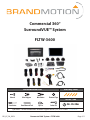
Commercial 360°
SurroundVUE™ System
FLTW-3600
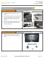
Recommended Tools Difficulty Level
Install Time
Panel Removal ToolScrew Driver Zip Ties Socket Set
Electrical TapeWire CuttersWire Strippers
Wrench
5hr - 8hr 30m
Questions? Call the Brandmotion technical support line at (734) 619-1250 or CLICK HERE

Page 2/11
RD_07_20_2023 Commercial 360° System - FLTW-3600
Vehicle Application:
Universal
Part Number: FLTW-3600
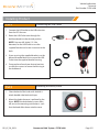
Kit Contents
Components for installing the FLTW-3600
Kit Contents:
7x Video Harnesses
3x Power Harnesses
1x Display Monitor
1x Monitor Housing
2x Monitor Housing Mounts
2x Monitor Housing Base Plates
1x ECU
1x Rotory Dial
4x Camera
HDMI, USB, and Remote Antenna Cords
1x USB Extension

Page 3/11
RD_07_20_2023 Commercial 360° System - FLTW-3600
Vehicle Application:
Universal
Part Number: FLTW-3600
Setting up Head Unit and 360° ECU
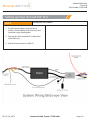
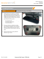
Part 1 Wiring the Display
1. Connect the 16-pin Radio Harness to the
vehicle’s factory wiring, following the pinout
of your specific vehicle.
2. Connect 16-pin Display Harness to Display.
3. Make sure the Head Unit powers on before
proceeding. NOTE: Black screen with small
box will appear if working properly.
Black = Ground
Red = Accessory
*Brown or Pink = Accessory
Yellow = Battery
Orange = Parking Lights (optional)
No other wires will be used
*Brown or Pink: Pink wire is equipped on older
models. Brown wire is on new models.
NOTE: This is the reverse wire, it needs to be
tapped into Accessory Power. DO NOT tap into
factory reverse wire

Page 4/11
RD_07_20_2023 Commercial 360° System - FLTW-3600
Vehicle Application:
Universal
Part Number: FLTW-3600
Setting up Head Unit and 360° ECU
Part 2 Wiring the 360 Harness
1. On the Camera Harness, connect Power
(yellow), Ground (black), and Accessory (red)
to vehicle wiring (See diagram).
2. Tape up the white wire and RCA cables from
Camera Harness.
3. Attach Camera Harness to 360 ECU.

Page 5/11
RD_07_20_2023 Commercial 360° System - FLTW-3600
Vehicle Application:
Universal
Part Number: FLTW-3600
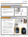
Cameras and Running Wires
Part 1
Part 2
Signal Wires (Left Turn, Right Turn and Reverse)
Mounting the Cameras
1. According to your specific vehicle, locate and
tap into the reverse signal wire and left and
right turn signal wires.
2. Connect Reverse signal and Left and Right
turn signal wires to the Red wire at the end of
the corresponding camera inputs for each on
the Camera Harness.
1. Determine the desired locations for the four
cameras. All cameras should be able to see the
edge of the vehicle at the bottom part of the
field of view.
Front Camera = Top of the grille
Left & Right Camera = Top of the vehicle at
the length midpoint
Rear Camera = Top center of the vehicle
2. Drill 1/4in hole in the vehicle at each proposed
camera location to run the wire. NOTE: Check
to ensure there is nothing behind your drill
location and you can access the other side.
3. Unscrew the three screws holding the camera
within the housing.
NOTE: If you would like to change the exit
location of the camera wire, do that now. You
can change the wire exit to the rear of the housing,
or the bottom of the housing.

Page 6/11
RD_07_20_2023 Commercial 360° System - FLTW-3600
Vehicle Application:
Universal
Part Number: FLTW-3600
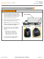
Installing Head Unit and 360 Computer
Part 1
4. Place the housing base plate either slightly
below the drilled hole or have the top hole
over top of the drill point, depending on your
camera wire preference. Using two screws
attach the base plate to the vehicle.
5. Run the camera wire through the drilled hole
and assemble the camera & housing.
NOTE: The camera has an arrow by the lens,
this arrow must be on top. Tighten the three
screws to set camera swivel in place.
6. Run camera extension wires through the
vehicle from each camera to the 360 ECU
location.
Red Connector = Left Camera
Blue Connector = Right Camera
Yellow Connector = Rear Camera
Black Connector = Front Camera
7. Connect each camera extension wire to
Camera Harness according to color.
SIDE CAMERA
REAR CAMERAFRONT CAMERA

Page 7/11
RD_07_20_2023 Commercial 360° System - FLTW-3600
Vehicle Application:
Universal
Part Number: FLTW-3600
Installing Product
Part 1 Connecting the ECU & Display
1. Connect HDMI cable to the 360 ECU and
Display.
2. Plug 360 Harness into the leftmost slot on 360
ECU, leaving the rightmost 4 pins empty, then
the other small 10-pin connector into the
Display
3. Plug in Dial Remote Receiver into the 3.5mm
jack. This can be mounted behind the dash
with no metal above it.
Part 2Mounting the Display to the Housing
1. Place the Display within the housing, and
screw in from the back using the provided M3
screws.

Commercial 360° System - FLTW-3600
Vehicle Application:
Universal
Part Number: FLTW-3600
Installing Product
Part 3Mounting the Housing in the Vehicle
1. Decide where in the vehicle you would like
the display to be mounted, there are three
options for the housing to be installed. Each
require the connector plate to be screwed in
a different location on the housing using the
provided plastic biting screws.
On top of the dash (see image 1)
On the front of the dash (see image 2)
From the headliner (see image 3)
2. Once your location is decided, use either
the stationary base plate or the swivel base
plate. Use the provided long screw and nut
and attached the connector plate to the base
plate.
3. Attach the base plate to your preferred
location using 4 screws.
Page 8/11
RD_07_20_2023

Page 9/11
RD_07_20_2023 Commercial 360° System - FLTW-3600
Vehicle Application:
Universal
Part Number: FLTW-3600
Installing Product
Part 5Mounting the Rotary Knob
1. Clean the back of the knob with alcohol &
attach double sided industrial tape
2. Mount the knob wherever is prefered by the
driver. NOTE: the knob battery cover slides
off, ensure the mounting orientation is such
that the knob slides down onto the cover.
Part 4Connecting the USB Outlet
1. Connect the USB outlet to the USB extension
from the ECU Harness
2. Route the USB Outlet wire through the
dashboard and into the desired position.
NOTE: You can drill a hole (1 5/16in
diameter) for the USB Outlet or use the
supplied bracket and screws to mount to the
dash.
3. If you are using the supplied bracket, use the
desired threaded lock nut to secure the USB
Outlet into the supplied bracket housing.
4. Once you have found your desired position,
use the four screws to secure the housing to
the dashboard.

Page 10/11
RD_07_20_2023 Commercial 360° System - FLTW-3600
Vehicle Application:
Universal
Part Number: FLTW-3600
Calibration
Part 1
Part 2
Preparing for Calibration
Digital Calibration
1. Create your own calibration mats by cutting
3’ x 3’ squares in a color that contrasts the
floor.
2. Place the interior (vehicle facing) edge of the
squares in line with the exterior edge of the
vehicle (See Photo). The squares will need to
be fully visible on each of the side cameras.
3. It is recommended to have the mats lay flat
during the calibration process to ensure an
accurate reading.
4. Navigate to the “SETTINGS” icon on the far
right of the selectable camera perspectives.
5. Select “Calibration” from the left menu, then
select “Edit” next to the Calibration option.
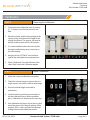
1. Select the 4 square calibration mat option
2. Check the camera images to ensure that two
target squares are clearly visible in each image.
3. Enter the vehicle length and width in
centimeters.
4. Continue entering vehicle measurements in
the the calibration menu. When complete,
press “Calibration” to advance to the next step.
5. Auto calibration will occur, but in the case that
one of the points fails. Manual splicing will be
required, if this is the case follow the prompt
to begin the manual calibration process.

Page 11/11
RD_07_20_2023 Commercial 360° System - FLTW-3600
Vehicle Application:
Universal
Part Number: FLTW-3600
Calibration
Part 1 Preparing for Calibration
6. Using the touch screen, move each crosshair
on each corner of the calibration target. The
order should be as shown in the reference
image.
7. When the crosshair is on the corner of the
mat, press the “next” icon to highlight the next
crosshair. Do this through all locations on each
corner and all sides of the vehicle.
8. Continue through the calibration setup.
When finished, press the “Advance” button.
Calibration is now complete.
-
 1
1
-
 2
2
-
 3
3
-
 4
4
-
 5
5
-
 6
6
-
 7
7
-
 8
8
-
 9
9
-
 10
10
-
 11
11


BrandMotion 07_2023_FLTW-3600-Instructions.pdf Installation guide
- Type
- Installation guide
Ask a question and I''ll find the answer in the document
Finding information in a document is now easier with AI