
Elite 1500 Plug ‘n’ Play
Adaptor Harness
HT-140921
Supported Models
MX-5 MAZDASPEED SPECIAL EDITION (FACTORY TURBO)
MX-5 NB 1.8 VCT (2000-2004)
MX-5 NB 1.8 NON-VCT (2000-2004)
Package Contents
THIS MAZDA MX-5 PACKAGE CONTAINS THE FOLLOWING:
- MAZDA MX-5 ELITE 1500 PLUG ‘N’ PLAY ADAPTOR (HT-140921)
- ELITE SERIES PLUG ‘N’ PLAY ADAPTOR HARNESS (HT-130201)
- INTAKE AIR TEMPERATURE SENSOR (HT-010200)
9 3 5 6 4 5 0 0 0 6 5 9 0

Application Notes
Elite Basemaps
MX-5 NON-VCT
A
B
C
D
E
F
G
H
I
J
K
L
ID JUMPER
MX-5 VCT
A
B
C
D
E
F
G
H
I
J
K
L
ID JUMPER
ALTERNATE CONFIGURATION
ALTERNATE CONFIGURATION
M N
P
O
M N
P
O
JUMPERS REQUIRED
B
D
H
I
L
JUMPERS REQUIRED
B
D
H
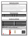
MAKE MODEL CODE ENGINE BASEMAP
MAZDA MX-5 SPECIAL EDITION (FACTORY TURBO) NB BP-4W HT-140921 EXXXX Mazda MX5 NB SE Turbo
MAZDA MX-5 1.8 VCT (00-04) NB BP-Z3 HT-140921 EXXXX Mazda MX5 NB VCT
MAZDA MX-5 1.8 NON-VCT (00-04) NB BP-4W HT-140921 EXXXX Mazda MX5 NB Non-VCT
Jumper ID Settings
MX-5 SPECIAL EDITION (FACTORY TURBO)
A
B
C
D
E
F
G
H
I
J
K
L
ID JUMPER
DEFAULT CONFIGURATION
M N
P
O
JUMPERS REQUIRED
B
D
F
H
J
THIS MAZDA MX-5 SPECIAL EDITION (FACTORY TURBO), VCT, NON-VCT ELITE 1500 PLUG ‘N’ PLAY ADAPTOR
HARNESS IS SUITABLE FOR USE WITH A HALTECH ECU ONLY.ELITE 1500
ENSURE THAT THE CORRECT BASEMAP IS LOADED BEFORE STARTING THE VEHICLE.
THE BASEMAP IS ONLY FOR USE AS A STARTING POINT AND THE ECU WILL REQUIRE APPROPRIATE TUNING.
HALTECH WILL NOT BE HELD RESPONSIBLE FOR ENGINE DAMAGE DUE TO THE IMPROPER USE OF BASEMAPS.
THE 16 PIN AUXILIARY CONNECTOR PROVIDES A NUMBER OF ADDITIONAL INPUT/OUTPUT LINKS TO THE
HALTECH ELITE ECU. THIS KIT IS SUPPLIED WITH SPARE PINS FOR USE WITH THE 16 PIN AUXILIARY CONNECTOR.
AN APPROPRIATE CRIMPING TOOL IS RECOMMENDED TO USE THE 16 PIN AUXILIARY CONNECTOR.
A CRIMPING TOOL KIT (PART # HT-070300) CAN BE PURCHASED AT WWW.HALTECH.COM
AFTER THE INSTALLATION OF THIS PLUG ‘N’ PLAY KIT, FACTORY PANELS MAY BE RE-INSTALLED.
Jumper
Connection Jumper Connection
A Connects Check Engine Light to Injector Output 5 (Elite 750) I Supplies VCT Solenoid (+) with +12V
B Connects Check Engine Light to Stepper 1 (Elite 1000-2500) J Connects Wastegate Solenoid to Wastegate Control Monitor
C Connects Alternator Control to Ignition Output 6 (Elite 750) K Connects VCT Solenoid Control to Injector Output 6 (Elite 750)
D Connects Alternator Control to Stepper 4 (Elite 1000-2500) L Connects VCT Solenoid Control to Stepper 3 (Elite 1000-2500)
E Connects Wastegate Solenoid to Ignition Output 5 (Elite 750) M Connects A/C Request to a 1k Pulldown
F Connects Wastegate Solenoid to Stepper 2 (Elite 1000-2500) N Connects Mass Air Flow Sensor to a 1k Pulldown
G Connnects ECR Relay to the on-board ECR Circuit (Elite 750) O Use when Alternator Control circuit requires +5V Signal
H Connects ECR Relay to DPO 6 (Elite 1000-2500) P Use when Alternator Control circuit requires +12V Signal
THIS MX-5 PLUG ‘N’ PLAY ADAPTOR HARNESS IS PRE-CONFIGURED FOR USE WITH AN ELITE 1500 ECU, HOWEVER,
THE JUMPERS ON BOARD CAN PROVIDE CAPABILITY WITH OTHER ECUS, INDICATED BELOW WITH (Elite 750-2500).
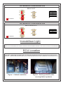
Immobiliser Light
NOTE: THIS PLUG ‘N’ PLAY PRODUCT DOES NOT SUPPORT THE FACTORY IMMOBILISER. YOU MAY NOTICE THE
LIGHT IN THE INSTRUMENT CLUSTER FLASHING, THIS IS NORMAL AND WILL NOT AFFECT VEHICLE PERFORMANCE.
ECU Location
THE FACTORY MAZDA MX-5 ECU IS LOCATED UNDER A PROTECTIVE PLATE ON THE PASSENGER SIDE
FOOT WELL. REMOVING THIS PANEL WILL ALLOW FOR THE INSTALLATION OF THIS HALTECH PLUG ’N’ PLAY
PRODUCT. THE FACTORY PROTECTIVE PLATE CAN BE RE-INSTALLED AFTER FITMENT OF HALTECH PRODUCTS.
Figure 1 - Haltech Installation
Figure 2 - Factory protective plate
covering Haltech products
NOTE: “EXXXX” IN THE BASEMAP FILE NAME DENOTES WHICH ECU MODEL THAT THE BASEMAP SUPPORTS.
E.G “HT-140921 E1000 Mazda MX5 NB VCT.e1000" IS THE BASEMAP CREATED FOR USE WITH AN ELITE 1000 ECU.

Application Notes
Elite Basemaps
MX-5 NON-VCT
A
B
C
D
E
F
G
H
I
J
K
L
ID JUMPER
MX-5 VCT
A
B
C
D
E
F
G
H
I
J
K
L
ID JUMPER
ALTERNATE CONFIGURATION
ALTERNATE CONFIGURATION
M N
P
O
M N
P
O
JUMPERS REQUIRED
B
D
H
I
L
JUMPERS REQUIRED
B
D
H
MAKE MODEL CODE ENGINE BASEMAP
MAZDA MX-5 SPECIAL EDITION (FACTORY TURBO) NB BP-4W HT-140921 EXXXX Mazda MX5 NB SE Turbo
MAZDA MX-5 1.8 VCT (00-04) NB BP-Z3 HT-140921 EXXXX Mazda MX5 NB VCT
MAZDA MX-5 1.8 NON-VCT (00-04) NB BP-4W HT-140921 EXXXX Mazda MX5 NB Non-VCT
Jumper ID Settings
MX-5 SPECIAL EDITION (FACTORY TURBO)
A
B
C
D
E
F
G
H
I
J
K
L
ID JUMPER
DEFAULT CONFIGURATION
M N
P
O
JUMPERS REQUIRED
B
D
F
H
J
THIS MAZDA MX-5 SPECIAL EDITION (FACTORY TURBO), VCT, NON-VCT ELITE 1500 PLUG ‘N’ PLAY ADAPTOR
HARNESS IS SUITABLE FOR USE WITH A HALTECH ECU ONLY.ELITE 1500
ENSURE THAT THE CORRECT BASEMAP IS LOADED BEFORE STARTING THE VEHICLE.
THE BASEMAP IS ONLY FOR USE AS A STARTING POINT AND THE ECU WILL REQUIRE APPROPRIATE TUNING.
HALTECH WILL NOT BE HELD RESPONSIBLE FOR ENGINE DAMAGE DUE TO THE IMPROPER USE OF BASEMAPS.
THE 16 PIN AUXILIARY CONNECTOR PROVIDES A NUMBER OF ADDITIONAL INPUT/OUTPUT LINKS TO THE
HALTECH ELITE ECU. THIS KIT IS SUPPLIED WITH SPARE PINS FOR USE WITH THE 16 PIN AUXILIARY CONNECTOR.
AN APPROPRIATE CRIMPING TOOL IS RECOMMENDED TO USE THE 16 PIN AUXILIARY CONNECTOR.
A CRIMPING TOOL KIT (PART # HT-070300) CAN BE PURCHASED AT WWW.HALTECH.COM
AFTER THE INSTALLATION OF THIS PLUG ‘N’ PLAY KIT, FACTORY PANELS MAY BE RE-INSTALLED.
Jumper
Connection Jumper Connection
A Connects Check Engine Light to Injector Output 5 (Elite 750) I Supplies VCT Solenoid (+) with +12V
B Connects Check Engine Light to Stepper 1 (Elite 1000-2500) J Connects Wastegate Solenoid to Wastegate Control Monitor
C Connects Alternator Control to Ignition Output 6 (Elite 750) K Connects VCT Solenoid Control to Injector Output 6 (Elite 750)
D Connects Alternator Control to Stepper 4 (Elite 1000-2500) L Connects VCT Solenoid Control to Stepper 3 (Elite 1000-2500)
E Connects Wastegate Solenoid to Ignition Output 5 (Elite 750) M Connects A/C Request to a 1k Pulldown
F Connects Wastegate Solenoid to Stepper 2 (Elite 1000-2500) N Connects Mass Air Flow Sensor to a 1k Pulldown
G Connnects ECR Relay to the on-board ECR Circuit (Elite 750) O Use when Alternator Control circuit requires +5V Signal
H Connects ECR Relay to DPO 6 (Elite 1000-2500) P Use when Alternator Control circuit requires +12V Signal
THIS MX-5 PLUG ‘N’ PLAY ADAPTOR HARNESS IS PRE-CONFIGURED FOR USE WITH AN ELITE 1500 ECU, HOWEVER,
THE JUMPERS ON BOARD CAN PROVIDE CAPABILITY WITH OTHER ECUS, INDICATED BELOW WITH (Elite 750-2500).
Immobiliser Light
NOTE: THIS PLUG ‘N’ PLAY PRODUCT DOES NOT SUPPORT THE FACTORY IMMOBILISER. YOU MAY NOTICE THE
LIGHT IN THE INSTRUMENT CLUSTER FLASHING, THIS IS NORMAL AND WILL NOT AFFECT VEHICLE PERFORMANCE.
ECU Location
THE FACTORY MAZDA MX-5 ECU IS LOCATED UNDER A PROTECTIVE PLATE ON THE PASSENGER SIDE
FOOT WELL. REMOVING THIS PANEL WILL ALLOW FOR THE INSTALLATION OF THIS HALTECH PLUG ’N’ PLAY
PRODUCT. THE FACTORY PROTECTIVE PLATE CAN BE RE-INSTALLED AFTER FITMENT OF HALTECH PRODUCTS.
Figure 1 - Haltech Installation
Figure 2 - Factory protective plate
covering Haltech products
NOTE: “EXXXX” IN THE BASEMAP FILE NAME DENOTES WHICH ECU MODEL THAT THE BASEMAP SUPPORTS.
E.G “HT-140921 E1000 Mazda MX5 NB VCT.e1000" IS THE BASEMAP CREATED FOR USE WITH AN ELITE 1000 ECU.

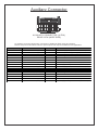
Auxiliary Connector
916
18
12
3
4
5
6
78
16 15 14 13 12 11 10 9
AUXILIARY CONNECTOR (16 PIN)
REAR VIEW (WIRE SIDE)
An auxiliary connector allows easy connection of additional ECU inputs and outputs.
Please see pinout information below for spare inputs and outputs available to this application.
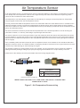
Air Temperature Sensor
Figure 3 - Air Temperature Sensor wiring
INSERT WIRE THROUGH PLUG, THEN CRIMP THE PIN INTO THE WIRE AND
DRAW BACK TO LOCK
LOOKING INTO FRONT OF CONNECTOR
Termination
A
B
Signal Ground
Air Temperature Signal
An air temperature sensor is a required sensor used in Volumetric Efficiency (VE) tuning to compensate for changes
in air density due to air temperature. Cold air has a higher density than warm air and therefore requires a greater
volume of fuel to maintain the same air/fuel ratio.
The Haltech ECU can automatically compensate the fuel delivery for changes in air density based on temperature
using the signal received from the air temperature sensor.
On many vehicles the OEM air temperature sensor is located either within the mass airflow sensor or molded into the
intake air manifold, however in performance applications the airflow sensor and air intake piping are often modified,
removed or replaced. For this reason an air temperature sensor (HT-010200) is provided for use as a substitute to the
factory air temperature sensor.
This sensor should be mounted to provide the best representation of the actual temperature of the air entering the
combustion chamber, i.e. after any turbocharger, supercharger and intercooler.
The sensor needs to be in the moving air stream to give fast response times and reduce heat soak effects. Be aware
in some situations, mounting the sensor into the inlet manifold (especially at the rear) may cause heat soak problems
(where the sensor reads the temperature of the manifold itself rather than the air that is moving through the manifold
into the engine).
Once a suitable position has been located for the air temperature sensor to be installed, a hole should be drilled and
tapped to accept the sensor. The intake manifold or inlet piping should be removed from the engine before this is done
to prevent any metal shavings or swarf entering the engine.
This package includes an air temperature sensor (HT-010200). This air temperature sensor should be installed by
utilising an auxiliary Analogue Voltage Input (AVI) and signal ground located on the 16 pin auxiliary connector.
Please refer to the auxiliary connector pinout table and sensor wiring diagram below.
Position (16 Pin Plug) Connection Function Notes
1From Haltech ECU (A9) +5V +5V Supply for Input Sensors (50mA Max)
2From Haltech ECU (A2) AVI 4 Spare Anal ogue Voltage Input
3From Mazda Pin 3720 ADDITIONAL I/O Fuel Tank Level Input
4From Haltech ECU (B14, B15, B16) SIGNAL GROUND Signal Ground For Input Sensors
5Not Used - -
6Not Used - -
7From Haltech ECU (B8) SPI 1 Spare SPI (Optional Flex Fuel Input)
8From Haltech ECU (A26) +12V (INJ) +12V Supply for Relays and Solenoids (500mA Max)
9From Haltech ECU (A9) +5V +5V Supply for Input Sensors (50mA Max)
10 From Haltech ECU (B23) CAN H CAN High Connection from ECU
11 From Haltech ECU (B24) CAN L CAN Low Connection from ECU
12 From Haltech ECU (B14, B15, B16) SIGNAL GROUND Signal Ground For Input Sensors
13 Not Used - -
14 Not Used - -
15 From Haltech ECU (B7) SPI 4 Spare Synchronised Pulsed Input
16 From Haltech ECU (A26) +12V (INJ) +12V Supply for Relays and Solenoids (500mA Max)

Auxiliary Connector
916
18
12
3
4
5
6
78
16 15 14 13 12 11 10 9
AUXILIARY CONNECTOR (16 PIN)
REAR VIEW (WIRE SIDE)
An auxiliary connector allows easy connection of additional ECU inputs and outputs.
Please see pinout information below for spare inputs and outputs available to this application.
Air Temperature Sensor
Figure 3 - Air Temperature Sensor wiring
INSERT WIRE THROUGH PLUG, THEN CRIMP THE PIN INTO THE WIRE AND
DRAW BACK TO LOCK
LOOKING INTO FRONT OF CONNECTOR
Termination
A
B
Signal Ground
Air Temperature Signal
An air temperature sensor is a required sensor used in Volumetric Efficiency (VE) tuning to compensate for changes
in air density due to air temperature. Cold air has a higher density than warm air and therefore requires a greater
volume of fuel to maintain the same air/fuel ratio.
The Haltech ECU can automatically compensate the fuel delivery for changes in air density based on temperature
using the signal received from the air temperature sensor.
On many vehicles the OEM air temperature sensor is located either within the mass airflow sensor or molded into the
intake air manifold, however in performance applications the airflow sensor and air intake piping are often modified,
removed or replaced. For this reason an air temperature sensor (HT-010200) is provided for use as a substitute to the
factory air temperature sensor.
This sensor should be mounted to provide the best representation of the actual temperature of the air entering the
combustion chamber, i.e. after any turbocharger, supercharger and intercooler.
The sensor needs to be in the moving air stream to give fast response times and reduce heat soak effects. Be aware
in some situations, mounting the sensor into the inlet manifold (especially at the rear) may cause heat soak problems
(where the sensor reads the temperature of the manifold itself rather than the air that is moving through the manifold
into the engine).
Once a suitable position has been located for the air temperature sensor to be installed, a hole should be drilled and
tapped to accept the sensor. The intake manifold or inlet piping should be removed from the engine before this is done
to prevent any metal shavings or swarf entering the engine.
This package includes an air temperature sensor (HT-010200). This air temperature sensor should be installed by
utilising an auxiliary Analogue Voltage Input (AVI) and signal ground located on the 16 pin auxiliary connector.
Please refer to the auxiliary connector pinout table and sensor wiring diagram below.
Position (16 Pin Plug) Connection Function Notes
1From Haltech ECU (A9) +5V +5V Supply for Input Sensors (50mA Max)
2From Haltech ECU (A2) AVI 4 Spare Anal ogue Voltage Input
3From Mazda Pin 3720 ADDITIONAL I/O Fuel Tank Level Input
4From Haltech ECU (B14, B15, B16) SIGNAL GROUND Signal Ground For Input Sensors
5Not Used - -
6Not Used - -
7From Haltech ECU (B8) SPI 1 Spare SPI (Optional Flex Fuel Input)
8From Haltech ECU (A26) +12V (INJ) +12V Supply for Relays and Solenoids (500mA Max)
9From Haltech ECU (A9) +5V +5V Supply for Input Sensors (50mA Max)
10 From Haltech ECU (B23) CAN H CAN High Connection from ECU
11 From Haltech ECU (B24) CAN L CAN Low Connection from ECU
12 From Haltech ECU (B14, B15, B16) SIGNAL GROUND Signal Ground For Input Sensors
13 Not Used - -
14 Not Used - -
15 From Haltech ECU (B7) SPI 4 Spare Synchronised Pulsed Input
16 From Haltech ECU (A26) +12V (INJ) +12V Supply for Relays and Solenoids (500mA Max)

CONNECTOR (24 PIN)
REAR VIEW (WIRE SIDE)
1
12
13
24
1
2
3
4
5
6
7
8
9
10
11
12
13
14
15
16
17
18
19
20
21
22
23
24
1
16
32 17
1
2
3
4
5
6
7
8
9
10
11
12
13
14
15
16
25
26
28
29
30
31
32 27 17
18
19
20
21
22
23
24
CONNECTOR (32 PIN)
REAR VIEW (WIRE SIDE)
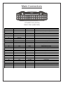
Main Connectors
Position (24 Pin Plug) ECU Connector (34 Pin Plug) Function Description
1 B1 TRIGGER Crankshaft Position Sensor
2 B2 HOME Camsahft Position Sensor
3 B3 AVI 7 Air Temperature Sensor
4 B4 AVI 8 Coolant Temperature Sensor
5 B5 TRIGGER - Not Used
6 B6 HOME - Not Used
7 B7 SPI 4 Spare Synchronsed Pulsed Input
8 B8 SPI 1 Spare SPI (Optional Flex Fuel Input)
9 B9 SPI 2 Vehicle Speed Sensor
10 B10 SPI 3 Clutch Switch
11 B11 +12V (ECU) Fused Power
12 B12 AVI 6 Brake Switch
13 B13 AVI 1 O2 Sensor
14 B14 SIGNAL GROUND Signal Ground For Input Sensors
15 B15 SIGNAL GROUND Signal Ground For Input Sensors
16 B16 SIGNAL GROUND Signal Ground For Input Sensors
17 B23 CAN HIGH Not Used
18 B24 CAN LOW Not Used
19 B19 DPO 4 Condensor Fan
20 B20 AVI 5 Mass Air Flow Signal
21 B21 KNOCK 1 Knock Sensor Signal
22 B22 KNOCK 2 Not Used
23 B25 DBW 1 Purge Control Solenoid (EVAP)
24 B26 DBW 2 Battery Light
Position (32 Pin Plug) ECU Connector (34 Pin Plug) Function Description
1 A1 DPO 2 A/C Control Relay
2 A2 AVI 4 Spare Analogue Voltage Input
3 A3 IGN 1 Ignition Coils 1 & 4
4 A4 IGN 2 Ignition Coils 2 & 3
5 A5 IGN 3 Thermofan
6 A6 IGN 4 VTCS Solenoid
7 Not Used - -
8 Not Used - -
9 A9 +5V +5V DC Sensor Supply
10 A10 BATTERY GROUND Battery Negative
11 A11 BATTERY GROUND Battery Negative
12 A12 +8V Not Used
13 A13 IGNITION INPUT Ignition Switch
14 A14 AVI 10 Throttle Position Sensor
15 A15 AVI 9 Manifold Pressure Signal
16 A16 AVI 2 Power Steering Switch
17 A17 AVI 3 A/C Request
18 A18 DPO 1 Tachometer
19 A19 INJ 1 Injector #1
20 A20 INJ 2 Injector #2
21 A21 INJ 3 Injector #3
22 A22 INJ 4 Injector #4
23 A23 DPO 3 Idle Control Motor (BAC)
24 A24 DPO 5 Fuel Pump Relay
25 A25 DPO 6 Not Used
26 A26 +12V (INJ) Fused Power
27 Not Used - -
28 Not Used - -
29 A31 STEP1 P1 Check Engine Light
30 A32 STEP2 P2 Wastegate Solenoid (Turbo Model Only) / Spare Output
31 A33 STEP3 P3 VCT Solenoid Control
32 A34 STEP4 P4 Alternator Control

CONNECTOR (24 PIN)
REAR VIEW (WIRE SIDE)
1
12
13
24
1
2
3
4
5
6
7
8
9
10
11
12
13
14
15
16
17
18
19
20
21
22
23
24
1
16
32 17
1
2
3
4
5
6
7
8
9
10
11
12
13
14
15
16
25
26
28
29
30
31
32 27 17
18
19
20
21
22
23
24
CONNECTOR (32 PIN)
REAR VIEW (WIRE SIDE)
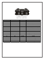
Main Connectors
Position (24 Pin Plug) ECU Connector (34 Pin Plug) Function Description
1 B1 TRIGGER Crankshaft Position Sensor
2 B2 HOME Camsahft Position Sensor
3 B3 AVI 7 Air Temperature Sensor
4 B4 AVI 8 Coolant Temperature Sensor
5 B5 TRIGGER - Not Used
6 B6 HOME - Not Used
7 B7 SPI 4 Spare Synchronsed Pulsed Input
8 B8 SPI 1 Spare SPI (Optional Flex Fuel Input)
9 B9 SPI 2 Vehicle Speed Sensor
10 B10 SPI 3 Clutch Switch
11 B11 +12V (ECU) Fused Power
12 B12 AVI 6 Brake Switch
13 B13 AVI 1 O2 Sensor
14 B14 SIGNAL GROUND Signal Ground For Input Sensors
15 B15 SIGNAL GROUND Signal Ground For Input Sensors
16 B16 SIGNAL GROUND Signal Ground For Input Sensors
17 B23 CAN HIGH Not Used
18 B24 CAN LOW Not Used
19 B19 DPO 4 Condensor Fan
20 B20 AVI 5 Mass Air Flow Signal
21 B21 KNOCK 1 Knock Sensor Signal
22 B22 KNOCK 2 Not Used
23 B25 DBW 1 Purge Control Solenoid (EVAP)
24 B26 DBW 2 Battery Light
Position (32 Pin Plug) ECU Connector (34 Pin Plug) Function Description
1 A1 DPO 2 A/C Control Relay
2 A2 AVI 4 Spare Analogue Voltage Input
3 A3 IGN 1 Ignition Coils 1 & 4
4 A4 IGN 2 Ignition Coils 2 & 3
5 A5 IGN 3 Thermofan
6 A6 IGN 4 VTCS Solenoid
7 Not Used - -
8 Not Used - -
9 A9 +5V +5V DC Sensor Supply
10 A10 BATTERY GROUND Battery Negative
11 A11 BATTERY GROUND Battery Negative
12 A12 +8V Not Used
13 A13 IGNITION INPUT Ignition Switch
14 A14 AVI 10 Throttle Position Sensor
15 A15 AVI 9 Manifold Pressure Signal
16 A16 AVI 2 Power Steering Switch
17 A17 AVI 3 A/C Request
18 A18 DPO 1 Tachometer
19 A19 INJ 1 Injector #1
20 A20 INJ 2 Injector #2
21 A21 INJ 3 Injector #3
22 A22 INJ 4 Injector #4
23 A23 DPO 3 Idle Control Motor (BAC)
24 A24 DPO 5 Fuel Pump Relay
25 A25 DPO 6 Not Used
26 A26 +12V (INJ) Fused Power
27 Not Used - -
28 Not Used - -
29 A31 STEP1 P1 Check Engine Light
30 A32 STEP2 P2 Wastegate Solenoid (Turbo Model Only) / Spare Output
31 A33 STEP3 P3 VCT Solenoid Control
32 A34 STEP4 P4 Alternator Control

V2.2
Need more help?
www.haltech.com/support [email protected]
AUS: +61 2 9729 0999 USA East: (888) 298 8116 USA West: (949) 490 5660
Europe: +43 720 883968 UK: 0121 285 6650 NZ: 09 887 0616
WARNING - HALTECH OFF-ROAD USAGE POLICY
It is unlawful to tamper with your vehicle's emissions equipment.
Haltech products are designed and sold for sanctioned off-road/competition non-emissions controlled vehicles only. Using
Haltech products for street/road use on public roads is prohibited by law. It is the responsibility of the installer and/or user
of this product to ensure compliance with all applicable local and federal laws and regulations. Please check with your
local vehicle authority before using any Haltech product
INSTALLATION OF HALTECH PRODUCTS
No responsibility whatsoever is accepted by Haltech for the fitment of Haltech Products. The onus is clearly on the
installer to ensure that both their knowledge and the parts selected are correct for that particular application. Any damage
to parts or consequential damage or costs resulting from the incorrect installation of Haltech products are totally the
responsibility of the installer.
Always disconnect the battery when doing electrical work on your vehicle. Avoid sparks, open flames or use of electrical
devices near flammable substances. Do not run the engine with a battery charger connected as this could damage the
ECU and other electrical equipment. Do not overcharge the battery or reverse the polarity of the battery or any charging
unit. Disconnect the Haltech ECU from the electrical system whenever doing any welding on the vehicle by unplugging
the wiring harness connector from the ECU. After completing the ECU installation, make sure there is no wiring left un-
insulated. Uninsulated wiring can cause sparks, short circuits and in some cases fire. Before attempting to run the engine
ensure there are no leaks in the fuel system. All fuel system components and wiring should be mounted away from heat
sources, shielded if necessary and well ventilated. Always ensure that you follow workshop safety procedures. If you're
working underneath a jacked-up car, always use safety stands!
HALTECH LIMITED WARRANTY
Unless specified otherwise, Haltech warrants its products to be free from defects in material or workmanship for a period
of 12 months from the date of purchase, valid in the original country of purchase only. Proof of purchase, in the form of a
bill of sale or receipted invoice, which indicates that the product is within the warranty period, must be presented to obtain
warranty service. Haltech suggests that the purchaser retain the dealer's dated bill of sale/receipt as evidence of the date
of retail purchase. If the Haltech product is found to be defective as mentioned above, it will be replaced or repaired if
returned prepaid along with proof of purchase. This shall constitute the sole liability of Haltech. To the extent permitted by
law, the foregoing is exclusive and in lieu of all other warranties or representations, either expressed or implied, including
any implied warranty of merchantability or fitness. In no event shall Haltech be liable for special or consequential
damages.
PRODUCT RETURNS
Please include a copy of the original purchase invoice along with the unused, undamaged product and its original
packaging. Any product returned with missing accessory items or packaging will incur extra charges to return the item to a
re-saleable condition. All product returns must be sent via a freight method with adequate tracking, insurance and proof of
delivery services. Haltech will not be held responsible for product returns lost during transit. The sale of any sensor or
accessory that is supplied in sealed packaging is strictly non-refundable if the sealed packaging has been opened or
tampered with. This will be clearly noted on the product packaging. If you do not accept these terms please return the
sensor in its original unopened packaging within 30 days for a full refund.
Returning a sensor or accessory product within 30 days of purchase: Product may be returned for credit or full
refund. (Any sealed packaging must not have been opened or tampered with)
Returning a sensor or accessory product after 30 days of purchase: Product may be returned for credit only (no
refunds given) and is subject to a 10% Restocking fee. (Any sealed packaging must not have been opened or tampered
with)
-
 1
1
-
 2
2
-
 3
3
-
 4
4
-
 5
5
-
 6
6
-
 7
7
-
 8
8


Ask a question and I''ll find the answer in the document
Finding information in a document is now easier with AI