Page is loading ...

www.superabrasive.com | [email protected]
facebook.com/superabrasive | twitter.com/superabrasive
LAVINA® User’s Group: linkedin.com/company/superabrasive-inc.
Superabrasive, Inc - Home Office
9411 Jackson Trail Road, Hoschton, GA 30548, USA
Ph +1 (706) 658-1122 | Fax +1 (706) 658-0357
LAVINA® V-32 Vacuum
Operating Manual
V-32-230 (230 Vol t), V-32-400 (400 Volt) and V-32-480 (480 Vol t)
Part of a complete system of LAVINA® vacuums and pre-separators.

Contact Superabrasive:
Technical Support: (800) 987-8403 | www.superabrasive.com | [email protected]
2
Table of Contents
Main Components and Controls ............................................................................... 3
Technical Data ............................................................................................................. 4
Included, Replacement, and Optional Parts / Accessories ..................................... 4
Safety Precautions ....................................................................................................... 5
Operation .................................................................................................................... 7
Waste Container Removal (Emptying the Dust) ...................................................... 8
Automatic Filter Cleaning System ............................................................................. 8
Replacing the Air Filters ............................................................................................. 9
Installing the HEPA Filter / HEPA Filter Kit ................................................................ 10
Longopac® Replacement (Changing Bags) ............................................................. 11
Installing Longopac® Rell Packs ............................................................................ 12
Maintenance .............................................................................................................. 13
Troubleshooting ........................................................................................................ 13
Recommended Spare Parts ...................................................................................... 15
Complete Parts List and Exploded Drawings ......................................................... 16
Sequencer Board Setting Instructions ..................................................................... 22
Electrical Diagrams ..................................................................................................... 23
Warranty and Returns ............................................................................................... 41
Handling, Transportation, and Storage .................................................................. 42
CE Certification ......................................................................................................... 42
Disposal ..................................................................................................................... 42
Manufacturer Contact Information ...........................................................................42

Contact Superabrasive:
Technical Support: (800) 987-8403 | www.superabrasive.com | [email protected]
3
Contact Superabrasive:
5
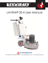
MAIN COMPONENTS AND CONTROLS
1) Top cover
2) Vacuum gauge
3) Latches (3 total)
4) Filter chamber
5) Vacuum push/pull handle (front/rear)
6) Waste container release handle (2 total)
7) Removable waste container
8) Caster wheel (2 total: 1 locking)
9) Fixed wheel (2 total)
10) Trolley frame
11) Vacuum suction inlet
12) Air compressor tank
13) Vacuum motor
14) Dust Collector information plate
1
2
3
7
4
6
11
8
9
10
12
14
13

Contact Superabrasive:
Technical Support: (800) 987-8403 | www.superabrasive.com | [email protected]
4
Part Number Description
Included: V-A-50 (A) Aluminum Floor Wand (M50)
V-S-C-3 (B) Steel Hose Connector (M60 to M88) Hose to Vacuum
V-FB-50 (C) Dry Floor Brush (M50)
V-H-P-8 (D) Polyurethane Anti-static Hose, 2 Rubber Cuffs (F60),
8 Meters (M60)
V-SR-C-1 (E) Steel / Rubber Connector (M60 to F50), 2 Pieces
V-SR-C-2 Steel / Rubber Connector (M60 to F76), 2 Pieces, 2 Clamps
Hose to Machine (not pictured)
V-S-F-5 (F) Air Filter Cartridge
Optional Parts: V-S-H-1 (G) HEPA Filter
Longopac® V-S-L-1 Replacement Longopac® (1 Refill Pack, 4 x 20mt bags)
Replacement
A. B.
D. E.
F. G.
C.
TECHNICAL DATA
INCLUDED, REPLACEMENT, AND OPTIONAL PARTS
V-32-230 V-32-480
Voltage 3 ph x 230 V 3 ph x 480 V
Amperage 26.3 Amps 15.2 Amps
Power 7.2 + 2 HP 7.5 + 2 HP
Motor 1 blower vacuum 1 blower vacuum
Filter 3 cartridges 3 cartridges
Filter Surface 87 ft287 ft2
Filter Cleaning compressor compressor
CFM 354 CFM 354 CFM
Water Lift 125 Inch 125 Inch
Longopac® yes yes
Vac Hose Port M88 M88
Cable Length 28.5 ft / 8.7 m 28.5 ft / 8.7 m
Weight 441 lbs 441 lbs

Contact Superabrasive:
Technical Support: (800) 987-8403 | www.superabrasive.com | [email protected]
5
SAFETY PRECAUTIONS
RECOMMENDED USE
The LAVINA® V-32 Vacuum is designed and manufactured for
use with concrete, terrazzo and natural stone oors. It is recom-
mended for use with LAVINA® machines. This vacuum is rated
for dry use only, and with a machine of appropriate size. For more
information, please contact Superabrasive.
PROHIBITED USE
The vacuum MUST NOT be used:
• For applications different from those stated in this manual
• For non-suitable materials (asbestos or other toxic materials)
• In environments which (1) Possess the risk of explosion, (2
Possess high concentration of powders or oil substances
in the air, (3) Possess the risk of re, (4) Feature inclem-
ent conditions, (5) Possess electromagnetic radiation
• The vacuum should be not connected to electrical power
when performing maintenance-related tasks
PREPARATION FOR WORK
Ensure that:
• You have closed the work area, so that no person unfamiliar
with operating the vacuum can enter the area
• The vacuum is not missing parts
• The vacuum is in an upright, working position
• All protection devices are working properly
• The electrical cable is free to move and follow the vacuum
easily. In order to keep the electrical cable from being
damaged, no vehicle should enter the area where electrical
cables are present.
ARREST FUNCTIONS
Functions for arresting of the machine include following:
• Button to stop the motor
SAFE USE
The LAVINA® V32 is designed to eliminate all potential risks as-
sociated with its use. However, accidents may occur if unskilled or
uninstructed workers fail to heed the list of potential risks below:
• Position Risks due to operator’s incorrect working position
• Tangling Risks due to wearing inappropriate working clothes
• Training Risks due to lack of operational training
NOTE: Machine operators should follow the instructions in the
manual at all times.
RESIDUAL RISKS
During normal operating and maintenance cycles, the operator is
exposed to some residual risks, which cannot be eliminated due
to the nature of machine operation.
BEFORE YOU BEGIN
• The working area must be clear from any debris or objects.
• A rst-time operator must always read the manual and heed
all safety instructions.
• All electric connections and cables must be inspected for
potential damage.
• Ground wire system of the power supply must be also
inspected.
• Perform general daily inspections of the vacuum and inspect
the vacuum before each use for any sign of damage.
• Inspect all safety devices.
• The vacuum/lters must be clean and the hose should be
connected.
OPERATING THE VACUUM
When operating the LAVINA® 25-L, be sure that no one else is
within close proximity to the vacuum. Never leave the vacuum
unattended while working. The electrical cable and hose must
move freely, be damage-free, and should never run beneath the
vacuum or machine. Check the oor prior to beginning any work,
and ensure that it’s not too uneven, which can cause damage to
the vacuum.
AFTER WORK IS COMPLETED
When work is complete, clean the vacuum and its surroundings
sufciently, empty all dust / debris, unplug the vacuum and wind
up the electrical cable, secure the hose, and store the vacuum in a
safe and secure place.
THE WORK AREA
Ensure that the area is free of unauthorized people or vehicles,
secure all cables and hoses, and always check the oor for debris.
PERSONAL PROTECTIVE EQUIPMENT
(PPE)
When operating the machine, always wear safety shoes, ear
protectors, safety gloves (especially when changing tools), and
suitable clothing. All persons within the immediate working area
must wear safety glasses with side shields.
OPERATOR
The operator must be aware of the vacuum’s work environment,
be properly trained prior to operating the equipment, and fully
understand this manual. Only one operator may work with the
machine at a single time The operator must understand and
interpret all the drawings and designs in manual, understand all
sanitation and safety regulations pertaining to its operation, have
oor grinding experience, know how to perform in an emergency
situation, and have an adequate technical knowledge and prepa-
ration.

Contact Superabrasive:
Technical Support: (800) 987-8403 | www.superabrasive.com | [email protected]
6
SAFETY PRECAUTIONS, Continued
• Superabrasive cannot predict all possible circumstances that could present a potential hazard. The warnings dened in this manual
should not be considered completely inclusive of all hazardous situations.
• It is the responsibility of the employer or vacuum owner to train any personnel that will be operating the vacuum unit, while complying
with all local laws and regulations.
• This specic vacuum cleaner has been designed for the vacuuming and collection of dusts and solid debris. This model is not intended
for any other uses or applications.
• IMPORTANT: Only use specied lters applicable to the operation of this vacuum cleaner.
• To ensure efcient operation of the vacuum cleaner, it must be protected from extreme environmental conditions and elements. This
may include rain, snow, hail, and airborne debris.
• The vacuum cleaner should only be operated in environments with a temperature between 41°F and 113°F (5°C to 45°C) and a maximum
relative humidity of 70%.
• The work environment for the vacuum cleaner should be clean, well-lit, and free of combustible elements.
• Before the vacuum cleaner is connected to the power source, ensure that the electrical voltage and frequency is correct for your specic
machine model.
• The vacuum cleaner should not be operated without the proper lters installed. This could possibly result in damage to the machine,
and cause harm to surrounding personnel.
• Do not open the waste container or motor head assembly while the vacuum cleaner is operating.
• Do not vacuum any ammable materials or substances such as fuels, solvents, etc. A vacuum cleaner must be specically designed and
labeled for such operation. When grinding epoxy, rst ensure that the epoxy is non-toxic.
• Do not vacuum any corrosive substances unless the vacuum cleaner is specically outtted with containers suitable for this purpose.
• Do not vacuum any burning, smoldering, or hot materials. This could result in a possible explosion and/or damage to the vacuum
components.
• If toxic or harmful substances accidentally enter the vacuum cleaner, the container and lters must be removed and cleaned immediately
using the proper protective equipment and safety procedures.
• When performing any type of maintenance procedures on the vacuum cleaner, be sure that the power switches are turned off and
the power cable is disconnected from the power source. Utilize the locking caster wheel to prevent movement while work is being
performed.
• Make sure the power cable is free from damage while operating the vacuum cleaner. If the power cable is found to be damaged,
discontinue use of the vacuum and replace the power cable immediately.
• When moving the vacuum cleaner, never pull on the power cable or vacuum hose. For this purpose, always use the designated handles
mounted on the machine.
• For this specic vacuum cleaner, sound tests indicate that the emitted noise is level is measured at a maximum of 76 decibels (dBA), for
a distance of 1 meter from the machine (and height of 1.60 meters). The vibrations emitted from the machine have been measured at a
maximum value of 2.5 m/s2.
• CAUTION: The National Institute for Occupational Safety and Health (NIOSH) recommends that exposure to noise in the working
environment be maintained below a level equivalent to 85 dBA for a period of eight hours, in order to minimize occupational, noise-
induced hearing loss. Any persons working in proximity of the vacuum cleaner should wear the proper hearing protection in order to
prevent hearing loss. Please refer to you local laws and regulations for further information on the matter.
• When storing the vacuum cleaner, the lter should be removed and cleaned, and the waste container should be emptied of debris.
Store the vacuum cleaner in temperatures between 32°F and 104°F (0°C and 40°C). Cover the vacuum cleaner in order to protect it from
accumulating debris and/or environmental elements.

Contact Superabrasive:
Technical Support: (800) 987-8403 | www.superabrasive.com | [email protected]
7
OPERATION
IMPORTANT: Before connecting the power cord to the power source, ensure that the electrical voltage corresponds with the
requirements identi ed on the information plate on the vacuum cleaner.
Make sure that the exible vacuum hose is securely attached to the vacuum pipe union and vacuum cleaner inlet.
Inspect the power cable (and extension cords) for any signs of wear or damage. Replace if necessary. Toggle the motor
switches to the “1” position to turn on the motors, and “0” position to turn them off.
CAUTION: Before switching the vacuum cleaner motors “on,” always make ensure that they are at a complete rest before
energizing. Also, before connecting the power supply, be sure the “start” switches are down.
Emergency Stop Button:
In emergency situations, the emergency stop button can be used to deactivate the vacuum cleaner. If the “stop suction”
button does not respond when pressed, the emergency stop button can also be used.
Thermal Release Indicator:
This indicator will illuminate when the circuit breaker(s) for the air compressor and/or vacuum motor has tripped. If the
vacuum cleaner has stopped and the indicator is illuminated, it will be necessary to inspect the machine and reset the
circuit breaker(s) before the vacuum motor can be re-energized. Please refer to the “Troubleshooting” section for further
information.
Locking Caster Wheel:
Of the 2 caster wheels located on the rear of the dust collector, one of the wheels may be locked. Locking the wheel will
prevent the vacuum from moving, and possibly causing damage or injury. The wheel should be locked on uneven surfaces to
prevent unexpected rolling or movement. To lock the caster wheel, follow the procedure shown below.
• To lock the caster wheel, press down on the metal tab labeled “STOP.”
• To unlock the caster wheel, press backwards on the metal tab protruding
from the top of the wheel assembly.

Contact Superabrasive:
Technical Support: (800) 987-8403 | www.superabrasive.com | [email protected]
8
handle
VACUUM GUAGE
There is a vacuum gauge dial located on the side of the vacuum cleaner.
The vacuum gauge indicator must always remain less than 2000 mm H2O while the vacuum cleaner is in operation.
CAUTION: If the vacuum gauge indicator remains at a reading greater than 2000 mm H2O, even after cleaning the lter, a
blockage is mostly likely present. Clean the vacuum hose and/or accessories of any blockages. Do not operate the vacuum
cleaner until the clog is removed.
CAUTION: While operating the vacuum cleaner, it is important to avoid extreme twisting, rolling, or bending of the vacuum
hose. This could result in damage to the vacuum motors.
WASTE CONTAINER REMOVAL (EMPTYING THE DUST)
To empty the waste, rst turn off all of the vacuum motors and disconnect the power cable from the power source. Then,
simultaneously lift both of the waste container release handles.
Use the attached waste container handle to move the waste container from beneath the vacuum cleaner.
IMPORTANT: When performing any work or maintenance on the waste container, a respirator should be worn in order to
prevent the inhalation of airborne dust and particles.
To reinstall the waste container,
perform the previous steps in reverse order.
AUTOMATIC FILTER CLEANING SYSTEM
The LAVINA® V-32 Vacuum Cleaner is tted with an automatic,
reverse-pulse, lter cleaning system. The system operates based
on a blowing frequency that is controlled by the timer settings.
Please refer to page 16 for additional information regarding the
automatic lter cleaning system (shown to the right).

Contact Superabrasive:
Technical Support: (800) 987-8403 | www.superabrasive.com | [email protected]
9
REPLACING THE AIR FILTER
To replace the vacuum lters, follow the procedures listed below:
IMPORTANT: All of the following procedures must be performed with the vacuum cleaner turned off and the power cable
disconnected from the power source. Before performing any work or maintenance on the vacuum cleaner, be sure to wear the
proper protective equipment (clothing, eye protection, and/or gloves).
• In order to prevent movement of the vacuum cleaner, place the locking caster wheel in the “stop” position. - Fig 1
• Loosen the hose clamps and remove the 4 hoses attached to the top cover. - Fig 2
• Release all of the latches securing the top cover assembly. - Fig 3
Refer to Figure 4 below for the remaining steps.
• Remove the top cover assembly and spacer ring below it, and set the pieces aside.
• Remove the center nut and 3 grounding straps from the threaded rod..
• Remove the 9 bolts that secure the lter cartridge retaining disc.
• Remove the lter cartridge retaining disc and set it aside.
• Remove the 3 old lters and install the new ones (Fig 5)
• Perform the previous steps in the reverse order for reassembly of the vacuum cleaner. Be sure to reinstall all of the
grounding straps when reassembling the vacuum.
IMPORTANT: The used lters and debris must be disposed of using the proper methods. Please contact your local,
environmental agency for information pertaining to your local laws and regulations.
Fig 1 Fig 2 Fig 3
Fig 4
lter clamp brackets
air jet hoses
hose clamp
lter
Fig 5:
Replacement
Ait Filter
Cartridge

Contact Superabrasive:
Technical Support: (800) 987-8403 | www.superabrasive.com | [email protected]
10
Fig 7 Fig 8 Fig 9Fig 6
INSTALLING THE HEPA FILTER / HEPA FILTER KIT
To install the HEPA lter kit (or lter), refer to the procedure listed below (see Fig 6 for a photo of the lter and kit):
IMPORTANT: All of the following procedures must be performed with the vacuum cleaner turned off and the power cable
disconnected from the power source. Before performing any work or maintenance on the vacuum cleaner, be sure to wear the
proper protective equipment (clothing, eye protection, and/or gloves).
• In order to prevent movement of the vacuum cleaner, place the locking caster wheel in the “stop” position (Fig 7).
• Locate the HEPA lter container located at the rear of the vacuum cleaner
• Release the 2 latches that secure the diffuser lter bag and top cover (Fig 8).
• Install the HEPA ler into the cotainer (Fig 9).
• Reinstall the top cover and secure the 2 latches on the HEPA lter container.
Important: The used lters must be disposed of using the proper methods. Please contact your local environmental agency for
information pertaing to your local laws and reguations.

Contact Superabrasive:
Technical Support: (800) 987-8403 | www.superabrasive.com | [email protected]
11
LONGOPAC BAG REPLACEMENT (CHANGING BAGS)
Deactivate all vacuum motors by placing the power switches in the OFF position.
IMPORTANT: Disconnect the electrical plug from the power source.
•Make sure that there is approximately 6-8 inches of an empty bag located between the bottom of the dust container and
the top of the debris/waste.
• Install 2 zip ties, or cable ties, around the plastic bag: 1 located above the top of the debris/waste, and a 2nd tie located
approximately 3-4 inches higher up on the bag). Both ties must be securely tightened in order to prevent the opening of
the bag and possible spillage.
•Using a sharp knife or scissors, cut across the entire section of plastic bag located between the 2 zip ties, or cable ties.
Remove and dispose of the bag section containing the dust and debris.
• Pull down on the bag until the end reaches the lower, bag-support plate.
IMPORTANT: When disposing of bags containing debris, be sure to use waste disposal containers and methods that fully
comply with all environmental laws and regulations that are applicable to your speci c country and location.

Contact Superabrasive:
Technical Support: (800) 987-8403 | www.superabrasive.com | [email protected]
12
Fig 13 Fig 14 Fig 15
Fig 16
Fig 17 Fig 18
INSTALLING LONGOPAC REFILL PACKS
When the plastic bag cartridge has reached the end, the plastic bag rell may be installed using the following procedures:
• Locate the 2 retaining levers located underneath the Longopac bag support ring (Fig 13).
• First pull down on the retaining levers, then rotate them 180 degrees so that the ends are pointing towards the center of
the machine (Fig 14).
• Pull down on the bag support ring to remove, and place aside on a level surface.
• Place the Longopac bag rell into the support ring. Ensure that the 2 ends of the rell are directed in an upwards
position. Pull the inner end of bag rell down over the inside surface of the bag support ring (Fig 15).
• Lift the bag support ring into place so that the bottom is located above the bottom edge of the hopper container (Fig 16).
• Rotate the 2 retaining levers 180 degrees so that the ends are pointing outward and holding the bag support ring in place
(Fig 17).
• Pull the outer edge of the bag down over the support ring until a zip tie, or cable tie, can be installed all the way around
the bag.
• After the zip tie has been securely installed, pull the bag down until the end reaches the lower, bag-support plate. The
vacuum cleaner is now ready for operation (Fig 18).

Contact Superabrasive:
Technical Support: (800) 987-8403 | www.superabrasive.com | [email protected]
13
MAINTENANCE
IMPORTANT: All of the following procedures must be performed with the vacuum cleaner turned off and the power cable
disconnected from the power source. Before performing any work or maintenance on the vacuum cleaner, be sure to wear the
proper protective equipment (clothing, eye protection, and/or gloves).
• In order to ensure safe and efcient operation of the vacuum cleaner, the following procedures should be performed
periodically (depending on the frequency of operation):
• Remove and inspect the lters for any signs of excessive wear or damage. Replace as necessary. (See section on “Filter
Removal”).
• Ensure that the sealing gaskets on the motor head assembly, lters or assemblies, and waste container are free of
excessive wear or damage. Replace as necessary.
• Inspect all electrical components (switches, plugs, cables, etc.) for damage or exposed wiring. Replace as necessary.
• Ensure that all screws, bolts, and nuts are properly tightened.
• Check the waste container level. Always clean and empty the container when the debris reaches a maximum of 75% of its
full capacity.
• Check the exible vacuum hose and accessories for signicant wear or damage. If holes are present, the vacuum cleaner’s
efciency will be reduced, and debris will leak into the work environment.
IMPORTANT: All major repair work should be performed by Superabrasive or an authorized repair facility.
VACUUM MOTOR SERVICING
During the life of the vacuum motor, the carbon brushes inside the motor may be replaced once. These brushes are
considered to be a ‘wear part’ and their replacement is not covered under the vacuum warranty. For additional information,
please contact Superabrasive, or an authorized service facility.
TROUBLESHOOTING
Vacuum Issue or Symptom Possible Cause Corrective Action
The vacuum fails to start or operate. There is insufcient power being supplied to the vacuum. Check the electrical cable, plug, and connections for
possible damage.
The electrical circuit breaker or GFI (Ground Fault
Interrupter) has tripped.
Reset the circuit breaker or GFI device(s).
Dust is leaking from the vacuum
during operation.
There are holes or cracks present in the vacuum hose or
tools.
Check the vacuum hose and tools for holes or cracks.
Replace if necessary.
There are holes present in the lter(s). Remove the lter(s) from the vacuum and inspect for holes
or tears. Replace if necessary.
The vacuum seals are misaligned or damaged. Make sure all rubber and foam seals are installed and
aligned properly. Replace if any visible damage is present.
The vacuum does not operate
efciently, or has weak suction
power.
The vacuum hose has an obstruction or holes present. Check the hose for obstructions and clear them as
necessary. Replace the hose if visible holes are present.
The vacuum dust container/bag is full. Empty the container, or replace the Longopac® section of
bag lled with dust and debris.
The vacuum lter(s) has excessive blockage. Activate the lter shaker lever to clean the lter (while the
vacuum is turned off). Replace if necessary.
The motor(s) are making excessive
noise.
The motor(s) is damaged. Contact Superabrasive or an authorized service facility.

Contact Superabrasive:
Technical Support: (800) 987-8403 | www.superabrasive.com | [email protected]
13
Fig 19 Fig 20 Fig 21 Fig 22
Fig 23 Fig 24 Fig 25
MAINTENANCE
AUTOMATIC FILTER CLEANING SYSTEM
The automatic lter cleaning system utilizes an air compressor. In order to ensure efcient operation of the system, routine maintenance
of the air compressor should be performed. This includes the intake air lter, compressor oil, and air tank. See the table below for the
recommended service intervals for system maintenanace.
MAINTENANCE SCHEDULE
In order to access the air compressor for maintenance, the waste container of the vacuum cleaner should be removed. After the waste
container is removed, the compressor can be accessed from the front of the machine (Fig 19).
Intake Air Filter: At a minimum, the intake air lter should be cleaned and inspected every 100 hours, or more frequently, depending on
working conditions. If the air lter becomes damaged, it should be discarded and replaced with a new air lter. The air lter assembly is
located on the top side of the air compressor. In order to remove the air lter, the center bolt needs to be removed using an Allen wrench (Fig
20, 21). The cover plate and air lter can then be removed. After the air lter has been thoroughly cleaned, the air lter and cover plate can
then be reinstalled.
Compressor Oil: The compressor oil level should be checked on a daily basis. When the oil reservoir is properly lled, the oil line shown
at the sight glass should intersect the red dot in the window (Fig 22). The sight glass can be seen through the cover of the vacuum cleaner,
towards the bottom of the machine (Fig 23).
If the oil level is above or below the mark, add or remove oil in order to adjust it to the correct level. The compressor oil should be drained
and relled after the rst 100 hours of operation. All subsequent oil changes should then be performed for every 300 hours of operation. The
recommended oil type for the compressor is API CC/SC SAE 40 (for cold climates, API CC/SC SAE 20 can be used). The drain plug for the
compressor oil is located just below the oil level slight glass. It can be removed using an Allen wrench. NOTE: Used compressor oil must be
disposed of using methods that fully comply with all local laws and regulations.
Air Tank: After a period of operation, condensate can accumulate in the air tank which should be removed via the drain valve located on
the bottom side of the air tank. The drain valve should be opened in order to allow condensate to drain out of the tank (before and after
operation) on a daily basis (Fig 24). When there is no longer any condensate coming out of the tank, the drain valve can be returned to the
closed position (Fig 25).
Daily After First 100 Hours Every 100 hours Every 300 Hours
Clean or replace intake air lter √
Drain and rell compressor oil √ √
Check oil level √
Drain condensate from air compressor tank √

Contact Superabrasive:
Technical Support: (800) 987-8403 | www.superabrasive.com | [email protected]
15
RECOMMENDED SPARE PARTS
DESCRIPTION PART #
Air Filter Cartridge (3 per vacuum) V-S-F-5
HEPA Filter V-S-H-1
Diffuser Filter Bag V-D-F-1
Gasket, Motor Head V-G-3
Gasket, Waste Container V-G-4
Latch AR2523
Spare Longopac® (1 Rell Pack, 4 X 20 mt. bags) V-S-L-1

Contact Superabrasive:
Technical Support: (800) 987-8403 | www.superabrasive.com | [email protected]
16

Contact Superabrasive:
Technical Support: (800) 987-8403 | www.superabrasive.com | [email protected]
17

Contact Superabrasive:
Technical Support: (800) 987-8403 | www.superabrasive.com | [email protected]
18

Contact Superabrasive:
Technical Support: (800) 987-8403 | www.superabrasive.com | [email protected]
19
V-S-F-4
V-L-1
V-G-4

Contact Superabrasive:
Technical Support: (800) 987-8403 | www.superabrasive.com | [email protected]
20
/