
NX-700/ NX-800
© B62-2112-00 (E)
09 08 07 06 05 04 03 02 01 00
VHF Digital traNscEiVEr/
UHF Digital traNscEiVEr
iNstrUctioN MaNUal
ÉMEttEUr-rÉcEPtEUr NUMÉriQUE VHF/
ÉMEttEUr-rÉcEPtEUr NUMÉriQUE UHF
MoDE D’EMPloi
traNscEPtor Digital VHF/
traNscEPtor Digital UHF
MaNUal DE iNstrUccioNEs
ricEtrasMEttitorE DigitalE VHF/
ricEtrasMEttitorE DigitalE UHF
MaNUalE Di istrUzioNi
VHF Digital FUNKgErÄt/
UHF Digital FUNKgErÄt
BEDiENUNgsaNlEitUNg
VHF DigitalE zENDoNtVaNgEr/
UHF DigitalE zENDoNtVaNgEr
gEBrUiKsaaNwijziNg
VHF SAYISAL ARAÇ TELSİZİ/
UHF SAYISAL ARAÇ TELSİZİ
KUllaNiM KilaVUzU
ΨΗΦΙΑΚΟΣ ΠΟΜΠΟΔΕΚΤΗΣ VHF/
ΨΗΦΙΑΚΟΣ ΠΟΜΠΟΔΕΚΤΗΣ UHF
ΟΔΗΓΙΕΣ ΧΡΗΣΗΣ


VHF Digital traNscEiVEr/
UHF Digital traNscEiVEr
NX-700/ NX-800
iNstrUctioN MaNUal
ENglisH
NOTIFICATION
This equipment complies with the essential requirements of
Directive 1999/5/EC.
The use of the warning symbol means the equipment is
subject to restrictions of use in certain countries.
This equipment requires a licence and is intended for use in
the countries as below.
at BE DK Fi Fr DE gr is
iE it li lU Nl No Pt Es
sE cH gB cY cz EE HU lV
lt Mt Pl sK si Bg ro
iso3166

Information on Disposal of Old Electrical and Electronic Equipment and Batteries
(applicable for EU countries that have adopted separate waste collection systems)
Products and batteries with the symbol (crossed-out wheeled bin) cannot be disposed as
household waste.
Old electrical and electronic equipment and batteries should be recycled at a facility capable
of handling these items and their waste byproducts.
Contact your local authority for details in locating a recycle facility nearest to you.
Proper recycling and waste disposal will help conserve resources whilst preventing
detrimental effects on our health and the environment.
Notice: The sign "Pb" below the symbol for batteries indicates that this battery contains lead.

i
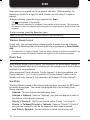
Thank You
We are grateful you have chosen Kenwood for your personal mobile applications.
This instruction manual covers only the basic operations of your NEXEDGE mobile radio. Ask your
dealer for information on any customized features they may have added to your radio.
nXDn™
NXDN™ is a protocol name for the new digital communication system using
4-level FSK technology which has been co-developed by Kenwood and Icom.
noTices To The user
◆ Government law prohibits the operation of unlicensed transmitters within the territories under
government control.
◆Illegaloperationispunishablebyneand/orimprisonment.
◆Referservicetoqualiedtechniciansonly.
SAFETY: It is important that the operator is aware of, and understands, hazards
common to the operation of any transceiver.
◆ EXPLOSIVE ATMOSPHERES (GASES, DUST, FUMES, etc.)
Turn OFF your transceiver while taking on fuel or while parked in gasoline service stations. Do
not carry spare fuel containers in the trunk of your vehicle if your transceiver is mounted in the
trunk area.
◆ INJURY FROM RADIO FREQUENCY TRANSMISSIONS
Do not operate your transceiver when somebody is either standing near to or touching the
antenna, to avoid the possibility of radio frequency burns or related physical injury.
◆ DYNAMITE BLASTING CAPS
Operating the transceiver within 500 feet (150 m) of dynamite blasting caps may cause them
to explode. Turn OFF your transceiver when in an area where blasting is in progress, or where
“TURN OFF TWO-WAY RADIO” signs have been posted. If you are transporting blasting caps
in your vehicle, make sure they are carried in a closed metal box with a padded interior. Do not
transmit while the caps are being placed into or removed from the container.
The AMBE+2™ voice coding Technology embodied in this product is protected by intellectual
property rights including patent rights, copyrights and trade secrets of Digital Voice Systems, Inc.
This voice coding Technology is licensed solely for use within this Communications Equipment.
The user of this Technology is explicitly prohibited from attempting to extract, remove,
decompile, reverse engineer, or disassemble the Object Code, or in any other way convert
the Object Code into a human-readable form. U.S. Patent Nos. #5,870,405, #5,826,222,
#5,754,974, #5,701,390, #5,715,365, #5,649,050, #5,630,011, #5,581,656, #5,517,511,
#5,491,772, #5,247,579, #5,226,084 and #5,195,166.

ii
PrecauTions
Observethefollowingprecautionstopreventre,personalinjury,andtransceiver
damage.
• Donotattempttocongurethetransceiverwhiledriving;itistoodangerous.
• Do not disassemble or modify the transceiver for any reason.
• Do not expose the transceiver to long periods of direct sunlight, nor place it near heating
appliances.
• If an abnormal odor or smoke is detected coming from the transceiver, switch the
transceiver power off immediately, and contact your Kenwood dealer.
• Useofthetransceiverwhileyouaredrivingmaybeagainsttrafclaws.Pleasecheck
and observe the vehicle regulations in your area.
• DonotuseoptionsnotspeciedbyKenwood.
◆ The transceiver operates in 12 V negative ground systems only! Check the battery polarity and
voltage of the vehicle before installing the transceiver.
◆ Use only a Kenwood optional DC power cable.
◆ Donotcutand/orremovethefuseholderontheDCpowercable.
For passenger safety, install the transceiver securely using an optional mounting bracket and screw
set so the transceiver will not break loose in the event of a collision.

iii
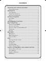
CONTENTS
UNPACKING AND CHECKING EQUIPMENT ....................................1
suPPlieD accessories .......................................................................1
PREPARATION ...................................................................................2
Tools requireD ................................................................................2
Power cable connecTion .................................................................2
insTalling The Transceiver ...............................................................3
GETTING ACQUAINTED .....................................................................4
FronT Panel .....................................................................................4
DisPlaY .............................................................................................5
PROGRAMMABLE FUNCTIONS ........................................................6
BASIC OPERATIONS ..........................................................................7
swiTching Power on/oFF ...............................................................7
aDjusTing The volume .......................................................................7
selecTing a Zone anD channel/grouP iD ..........................................7
TransmiTTing .....................................................................................7
receiving ..........................................................................................8
MENU MODE .......................................................................................9
menu access ....................................................................................9
menu conFiguraTion .........................................................................9
characTer enTrY ...........................................................................11
SCAN .................................................................................................12
TemPorarY channel lockouT..........................................................12
PrioriTY scan .................................................................................12
scan reverT ...................................................................................12
scan DeleTe/aDD ............................................................................13
PrioriTY-channel selecT ................................................................13
FleetSync: ALPHANUMERIC 2-WAY PAGING FUNCTION ............14
selcall (selecTive calling) ...........................................................14
sTaTus message .............................................................................14
shorT/long messages ....................................................................15
gPs rePorT ...................................................................................15

iv
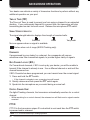
ADVANCED OPERATIONS ..............................................................16
DTmF (Dual Tone mulTi FrequencY) calls ...................................16
Trunking calls (analog) ...............................................................16
emergencY calls ...........................................................................17
scrambler ......................................................................................17
signaling ........................................................................................18
clock .............................................................................................19
lcD brighTness .............................................................................19
horn alerT ....................................................................................19
Public aDDress (Pa) ......................................................................19
BACKGROUND OPERATIONS ........................................................20
Time-ouT Timer (ToT) .....................................................................20
signal sTrengTh inDicaTor .............................................................20
comPanDer .....................................................................................20
busY channel lockouT (bcl) ........................................................20
conTrol channel hunT ..................................................................20
PTT iD ...........................................................................................20
VGS-1 OPTIONAL VOICE GUIDE & STORAGE UNIT .....................21
voice recorDer ..............................................................................21
voice guiDe ....................................................................................22

1
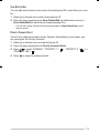
UNPACKING AND CHECKING EQUIPMENT
Note: The following unpacking instructions are for use by your Kenwood dealer, an authorized
Kenwood service facility, or the factory.
Carefully unpack the transceiver. We recommend that you identify the items listed in
the following list before discarding the packing material. If any items are missing or
have been damaged during shipment, le a claim with the carrier immediately.
Supplied AcceSSorieS
• DC power cable ...............................................1
• Fuse (15 A) ................................................2
• Mounting bracket ..............................................1
• Screw set
• 5 x 16 mm self-tapping screw ..................................4
• Hex-headed screw with washer ................................ 4
• Spring washer ..............................................4
• Flat washer ................................................4
• Instruction manual .............................................1

2
Various electronic equipment in your vehicle may malfunction if they are not properly protected
from the radio frequency energy which is present while transmitting. Electronic fuel injection, anti-
skid braking, and cruise control systems are typical examples of equipment that may malfunction.
If your vehicle contains such equipment, consult the dealer for the make of vehicle and enlist
his/her aid in determining if they will perform normally while transmitting.
Note: The following preparation instructions are for use by your Kenwood dealer, an authorized
Kenwood service facility, or the factory.
ToolS required
Note: Before installing the transceiver, always check how far the mounting screws will extend
below the mounting surface. When drilling mounting holes, be careful not to damage vehicle wiring
or parts.
The following tools are required for installing the transceiver:
• 1/4 inch (6 mm) or larger electric drill
• 5/32 inch (4.2 mm) drill bit for the self-tapping screws used to mount the optional
mounting bracket
• Circle cutters
power cAble connecTion
◆ The transceiver operates in 12 V negative ground systems only! Check the battery polarity and
voltage of the vehicle before installing the transceiver.
◆ Use only a Kenwood optional DC power cable.
◆ Do not cut and/or remove the fuse holder on the DC power cable.
1 Check for an existing hole, conveniently located in the rewall, where a power
cable can be passed through. If no hole exists, use a circle cutter to drill the
rewall, then install a rubber grommet.
2 Run the two power cable leads through the rewall and into the engine
compartment, from the passenger compartment.
3 Connect the red lead to the positive (+) battery terminal and the black lead to
the negative (–) battery terminal.
• Locate the fuse as close to the battery as possible.
4 Coil and secure the surplus cable with a retaining band.
• Be sure to leave enough slack in the cables so the transceiver can be removed for
servicing while keeping the power applied.
PREPARATION

3
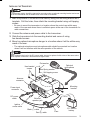
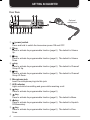
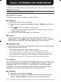
inSTAlling The TrAnSceiver
For passenger safety, install the transceiver securely using an optional mounting bracket and screw
set so the transceiver will not break loose in the event of a collision.
1 Mark the position of the holes in the dash by using the mounting bracket as a
template. Drill the holes, then attach the mounting bracket using self-tapping
screws.
• Be sure to mount the transceiver in a location where the controls are within easy
reach of the user and where there is sufcient space at the rear of the transceiver for
cable connections.
2 Connect the antenna and power cable to the transceiver.
3 Slide the transceiver into the mounting bracket and secure it using
hex-headed screws.
4 Mount an optional microphone hanger in a location where it will be within easy
reach of the user.
• The optional microphone and microphone cable should be mounted in a location
where it will not interfere with the safe operation of the vehicle.
When replacing the fuse in the DC power cable, be sure to replace it with a fuse of the same value.
Never replace a fuse with a fuse that has a higher value.
Hex-headed
screws
DC power
cable
Mounting
bracket
Antenna
connector
Power input
connector
Fuse
Black (–) cable
Red (+) cable
12 V vehicle
battery
Optioinal
microphone
Ignition
sense cable
Flat washer
Spring washer
Self-tapping screw
External
speaker jack

4
GETTING ACQUAINTED
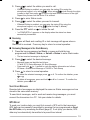
FronT pAnel
① (power) switch
Press and hold to switch the transceiver power ON and OFF.
② key
Press to activate its programmable function {page 6}. The default is Volume
Up.
③ key
Press to activate its programmable function {page 6}. The default is Volume
Down.
④ key
Press to activate its programmable function {page 6}. The default is Channel/
Group ID Up.
⑤ key
Press to activate its programmable function {page 6}. The default is Channel/
Group ID Down.
⑥ Microphone jack
Insert the microphone plug into this jack.
⑦ LED indicator
Lights red while transmitting and green while receiving a call.
⑧ key
Press to activate its programmable function {page 6}.
⑨ key
Press to activate its programmable function {page 6}. The default is Menu.
⑩ key
Press to activate its programmable function {page 6}. The default is Squelch
Off Momentary.
⑪ key
Press to activate its programmable function {page 6}. The default is Zone
Down.
Optional
microphone

5
⑫ key
Press to activate its programmable function {page 6}. The default is Zone Up.
⑬ key
Press to activate its programmable function {page 6}.
⑭ Speaker
Internal speaker
⑮ PTT (Push-to-Talk) switch
Press and hold this switch, then speak into the microphone to call a station.
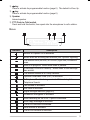
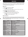
diSplAy
Indicator Description
Monitor or Squelch Off is activated.
Blinks when an incoming call matches your Optional Signaling.
The current zone (left icon) or CH/GID (right icon) is added to
scan.
Scan is in progress. Blinks while scan is paused.
A message is stored in memory. Blinks when a new message
has arrived.
The current channel is a Priority channel.
Operator Selectable Tone (OST) is activated.
A Telephone ID call is being received. Blinks during Auto
Telephone Search.
Talk Around is activated.
Site Lock is activated.
Signal strength indicator {page 20}.
Scrambler/ Encryption is activated.
Auto Recording on the VGS-1 option is activated.
Auto Reply Message is activated.
The AUX A function is activated.
Lone Worker is activated.
The AUX B function is activated.

6
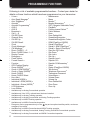
PROGRAMMABLE FUNCTIONS
Following is a list of available programmable functions. Contact your dealer for
details on those functions which have been programmed on your transceiver.
• 2-tone 1
• Auto Reply Message 2
• Auto Telephone 3
• Autodial 4
• Autodial Programming 4
• AUX A
• AUX B
• Broadcast 5
• Call 1 ~ 6
• CH/GID Down
• Channel Entry
• CH/GID Up
• CH/GID Recall
• Clock
• Clock Adjustment
• CW Message 6
• Direct CH/GID 1 ~ 5
• Direct CH/GID Select 1 ~ 5
• Display Format
• Emergency 7
• Fixed Volume
• Forced Search 5
• Function
• GPS Position Display
• Group (NXDN) 6
• Group + SDM (NXDN) 8
• Group + Status (NXDN) 8
• Home CH/GID
• Home CH/GID Select
• Horn Alert
• Individual (NXDN) 8
• Individual + SDM (NXDN) 8
• Individual + Status (NXDN) 8
• LCD Brightness
• Lone Worker
• Maintenance
• Menu
• Monitor 9
• Monitor Momentary 9
• OST (Operator Selectable Tone) 1
• Playback 2
• Priority-channel Select 10
• Public Address
• Scan
• Scan Delete/Add
• Scrambler/Encryption
• Scrambler/Encryption Code 8
• SDM (FleetSync/ NXDN)
• Selcall (FleetSync) 4
• Selcall + SDM (FleetSync) 4
• Selcall + Status (FleetSync) 4
• Send the GPS data
• Site Down 5
• Site Lock 5
• Site Up 5
• Squelch Level 1
• Squelch Off 1
• Squelch Off Momentary 1
• Stack
• Status (FleetSync/ NXDN)
• Talk Around 9
• Telephone Disconnect 3
• Transceiver Password
• Voice Memo 2
• Volume Down
• Volume Up
• Zone Delete/Add
• Zone Down
• Zone Up
1 Available only for Analog Conventional operation
2 Available only if the VGS-1 optional board has been installed.
3 Available only for Analog Trunking operation.
4 Available only for Analog Conventional and Analog Trunking operation.
5 Available only for NXDN Trunking operation.
6 Available only for NXDN Conventional operation.
7 Emergency can be programmed only on the key and an optional auxiliary switch, such as an
emergency foot switch.
8 Available only for NXDN Conventional and NXDN Trunking operation.
9 Available only for Analog Conventional, Analog Trunking, and NXDN Conventional operation.
10 Available only for Analog Conventional and NXDN Conventional operation.

7
BASIC OPERATIONS
SwiTching power on/oFF
Press and hold the switch for approximately 1 second to turn the transceiver
power ON. Press and hold the switch again to turn the transceiver OFF.
■ Transceiver Password
If the transceiver is password protected, “PASSWORD” will appear on the
display when the power is turned ON. To unlock the transceiver, enter the
password:
1 Select a character using / .
• If you are using a microphone keypad, you can enter the password direclty.
2 Press to enter the selected character.
• This step is unnecessary when using the keypad.
3 Repeat steps 1 and 2 to enter the entire password.
• Press or # to delete a character. Press and hold or # to delete all
characters.
4 Press or to conrm the entry.
• If you enter an incorrect password, an error tone sounds and the transceiver
remains locked.
• The password can contain a maximum of 6 digits.
AdjuSTing The volume
Press the keys programmed as Volume Up/ Volume Down to adjust the volume.
SelecTing A Zone And chAnnel/group id
Select the desired zone using / (default). Each zone contains a group of
channels.
Select the desired channel/group ID using / (default). Each channel/group ID
is programmed with settings for transmitting and receiving.
• You can toggle the display between the zone and channel/group ID names and number
by pressing the key programmed as Display Format, or by accessing the Menu {page 9}.
Note: If the default settings for / and / have been changed, use the appropriate keys to
select the zone and channel/group ID.
TrAnSmiTTing
1 Select the desired zone and channel/group ID.
2 Press the key programmed as Monitor or Squelch Off to check whether or
not the channel is free.
• If the channel is busy, wait until it becomes free.

8
3 Press the PTT switch and speak into the microphone. Release the PTT switch
to receive.
• For best sound quality, hold the microphone approximately 1.5 inches (3 ~ 4 cm)
from your mouth.
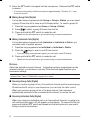
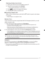
■ Making Group Calls (Digital)
If a key has been programmed with Group or Group + Status, you can select
a group ID from the list to make a call to those parties. To select a group ID:
1 Press the key programmed as Group or Group + Status.
2 Press / to select a group ID/name from the list.
3 Press and hold the PTT switch to make the call.
• Speak into the microphone as you would during a normal transmission.
■ Making Individual Calls (Digital)
If a key has been programmed with Individual or Individual + Status, you
can make calls to specic persons.
1 Press the key programmed as Individual or Individual + Status.
2 Press
the / keys
to select a unit ID from the list.
• If you are using a microphone keypad, you can enter a unit ID directly.
3 Press and hold the PTT switch to make the call.
• Speak into the microphone as you would during a normal transmission.
receiving
Select the desired zone and channel. If signaling has been programmed on the
selected channel, you will hear a call only if the received signal matches your
transceiver settings.
Note: Signaling allows your transceiver to code your calls. This will prevent you from listening to
unwanted calls. Refer to “SIGNALING” on page 18 for details.
■ Receiving Group Calls (Digital)
When you receive a group call on a Conventional channel and the received group
ID matches the ID set up on your transceiver, you can hear the caller’s voice.
When you receive a group call on a Trunking channel, the transceiver
automatically switches to the communications channel to receive the call.
■ Receiving Individual Calls (Digital)
When you receive an individual call on a Conventional channel, a ringing tone
will sound and the caller’s ID will appear on the display. To respond to the call,
press and hold the PTT switch and speak into the microphone as you would
during a normal transmission.

9
Many functions on this transceiver are selected or congured through the Menu
instead of physical controls. Once you become familiar with the Menu system,
you will appreciate the versatility it offers.
menu AcceSS
1 Press the key programmed as Menu.
2 Press / to select a Menu item.
• If you are using a microphone keypad, you can enter a Menu number directly.
3 Press to set up the selected Menu item.
4 Press / to select your desired setting.
• For settings with more than 1 level, repeat steps 3 and 4.
5 Press to set the selected setting and exit Menu mode.
• Press at any time to return to the previous display.
• Press at any time to exit Menu mode.
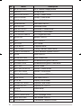
menu conFigurATion
Some transceiver keys may already be programmed with functions listed in the
Menu. Those functions can be accessed directly by pressing the key. All other
functions can still be accessed using the transceiver Menu. The following table
lists the available Menu items.
No. Menu Description
01 2-TONE 2-tone Mode
02 AUTO REPLY MSG Auto Reply Message ON/OFF
03 AUTO TELEPHONE Auto Telephone
04 AUTO DIAL Autodial Mode
05 AUTO DIAL PROG Autodial Programming Mode
06 AUX A AUX A ON/OFF
07 AUX B AUX B ON/OFF
08 BROADCAST Broadcast ON/OFF
09 CLOCK Clock ON/OFF
10 CLOCK ADJUST Clock Adjustment mode
11 DIRECT CH1 SEL Direct CH/GID 1 ~ 5 Select
12 DISP FORMAT Display Format ON/OFF
13 FIXED VOLUME Fixed Volume
14 FORCED SEARCH Forced Search
MENU MODE

10
No. Menu Description
15 GPS POS DISP GPS Position Display mode
16 GROUP Group mode
17 GROUP+STATUS Group + Status mode
18 GROUP+SDM Group + SDM mode
19 HOME CH SEL Home CH/GID Select
20 HORN ALERT Horn Alert ON/OFF
21 INDIVIDUAL Individual mode
22 INDIV+STATUS Individual + Status mode
23 INDIV+SDM Individual + SDM mode
24 LCD BRIGHTNESS LCD Brightness level
25 MONITOR Monitor ON/OFF
26 OST OST ON/OFF
27 OST LIST OST mode
28 PLAYBACK Playback mode
29 PRI CH SEL Priority Channel Select mode
30 PUBLIC ADDRESS Public Address System ON/OFF
31 SCAN Scan ON/OFF
32 SCAN DEL/ADD Scan Delete/Add
33 SCRAM/ENCRYP Scrambler/Encryption ON/OFF
34 SCRAM CODE Scrambler/Encryption Code mode
35 SELCALL Selcall mode
36 SELCALL+STATUS Selcall + Status mode
37 SELCALL+SDM Selcall + SDM mode
38 SEND GPS DATA Transmit your GPS data
39 SITE LOCK Site Lock ON/OFF
40 SITE No. Display Site Number
41 SQUELCH LEVEL Squelch Level mode
42 SQUELCH OFF Squelch Off ON/OFF
43 STACK Stack mode
44 STATUS Status mode
45 SHORT MESSAGE Short Message mode
46 TALK AROUND Talk Around ON/OFF
47 PASSWORD Transceiver Password mode

11
No. Menu Description
48 VOICE MEMO Voice Memo mode
49 ZONE DEL/ADD Zone Delete/Add
chArAcTer enTry
There are 2 methods available for entering characters:
1) Pressing the / keys
Press / to cycle the characters from A ~ Z, 0 ~ 9, and a space (default
settings).
You can also assign a character to an optional key and later press that key to
recall the assigned character: A ~ Z, a ~ z, 0 ~ 9, or a space and characters.
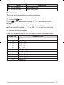
2) Using the microphone keypad
Press the microphone keys to enter characters as shown in the table below:
DTMF Key Character Cycle
1 1
2A B C 2
3D E F 3
4G H I 4
5J K L 5
6M N O 6
7P Q R S 7
8T U V 8
9W X Y Z 9
0[space] 0

12
SCAN
Scan monitors for signals on the transceiver channels. While scanning, the
transceiver checks for a signal on each channel and only stops if a signal is
present.
To begin scanning, press the key programmed as Scan.
• The icon appears on the display.
• When a signal is detected on a channel, Scan pauses at that channel. The transceiver
will remain on the busy channel until the signal is no longer present, at which time Scan
resumes.
To stop scanning, press the Scan key again.
Note: To use Scan, there must be at least 2 channels in the scan sequence.
TemporAry chAnnel lockouT
During scan, you can temporarily remove specic channels from the scanning
sequence by selecting them and pressing the key programmed as Scan Delete/
Add.
• The channel is no longer scanned. However, when scanning is ended and restarted, the
channels are reset and deleted channels will again be in the scanning sequence.
prioriTy ScAn
Note: To use Priority Scan, a Priority channel must be programmed.
When using a single Priority channel, the transceiver will automatically change to
the Priority channel when a call is received on that channel, even if a call is being
received on a normal channel.
When using dual Priority channels, Priority channel 1 is given precedence over
Priority channel 2. So, if a call is received on Priority channel 1 while a call is
already on Priority channel 2, the transceiver will change to Priority channel 1.
ScAn reverT
The Scan Revert channel is the channel selected when you press the PTT switch
to transmit during scan. Your dealer can program one of the following Scan
Revert channels:
• Selected: The last channel selected before scan.
• Selected + Talkback: Same as “Selected”, plus you can respond to calls on
the channel at which scan is paused.
• Priority 1/ Priority 2: The Priority channel (either Priority 1 or Priority 2).
• Priority 1 + Talkback/ Priority2 + Talkback: Same as “Priority 1/ Priority 2”,
plus you can respond to calls on the channel at which scan is paused.
• Last Called + Selected: The last channel on which you receive a call.
Page is loading ...
Page is loading ...
Page is loading ...
Page is loading ...
Page is loading ...
Page is loading ...
Page is loading ...
Page is loading ...
Page is loading ...
Page is loading ...
Page is loading ...
-
 1
1
-
 2
2
-
 3
3
-
 4
4
-
 5
5
-
 6
6
-
 7
7
-
 8
8
-
 9
9
-
 10
10
-
 11
11
-
 12
12
-
 13
13
-
 14
14
-
 15
15
-
 16
16
-
 17
17
-
 18
18
-
 19
19
-
 20
20
-
 21
21
-
 22
22
-
 23
23
-
 24
24
-
 25
25
-
 26
26
-
 27
27
-
 28
28
-
 29
29
-
 30
30
-
 31
31


Kenwood NEXEDGE NX-800 series User manual
- Type
- User manual
- This manual is also suitable for
Ask a question and I''ll find the answer in the document
Finding information in a document is now easier with AI
Related papers
-
Kenwood NX-300 Owner's manual
-
Kenwood NX-210 User manual
-
-
Kenwood NEXEDGE NX-800 series User manual
-
Kenwood NX-300SE Owner's manual
-
-
-
Kenwood TK-D740 User manual
-
Kenwood TK-7180 User manual
-