ESAB MultiPower 460 Pulse Upgrade Kit Installation guide
- Category
- Welding System
- Type
- Installation guide

0558009127
June 2009
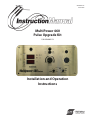
MultiPower 460
Pulse Upgrade Kit
Installation and Operation
Instructions
P/N 0558009123

2
This equipment will perform in conformity with the description thereof contained in this manual and accompa-
nying labels and/or inserts when installed, operated, maintained and repaired in accordance with the instruc-
tions provided. This equipment must be checked periodically. Malfunctioning or poorly maintained equipment
should not be used. Parts that are broken, missing, worn, distorted or contaminated should be replaced imme-
diately. Should such repair or replacement become necessary, the manufacturer recommends that a telephone
or written request for service advice be made to the Authorized Distributor from whom it was purchased.
This equipment or any of its parts should not be altered without the prior written approval of the manufacturer.
The user of this equipment shall have the sole responsibility for any malfunction which results from improper
use, faulty maintenance, damage, improper repair or alteration by anyone other than the manufacturer or a ser-
vice facility designated by the manufacturer.
BE SURE THIS INFORMATION REACHES THE OPERATOR.
YOU CAN GET EXTRA COPIES THROUGH YOUR SUPPLIER.
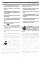
These INSTRUCTIONS are for experienced operators. If you are not fully familiar with the
principles of operation and safe practices for arc welding and cutting equipment, we urge
you to read our booklet, “Precautions and Safe Practices for Arc Welding, Cutting, and
Gouging,” Form 52-529. Do NOT permit untrained persons to install, operate, or maintain
this equipment. Do NOT attempt to install or operate this equipment until you have read
and fully understand these instructions. If you do not fully understand these instructions,
contact your supplier for further information. Be sure to read the Safety Precautions be-
fore installing or operating this equipment.
CAUTION
USER RESPONSIBILITY
READ AND UNDERSTAND THE INSTRUCTION MANUAL BEFORE INSTALLING OR OPERATING.
PROTECT YOURSELF AND OTHERS!

3
TABLE OF CONTENTS
1.0 Safety Precautions ....................................................................................5
1.1 Safety - English ..................................................................................5
1.2 Safety - Spanish .................................................................................9
1.3 Safety - French .................................................................................13
2.0 Description ..........................................................................................17
2.1 Description ......................................................................................17
2.2 Pulse Control Panel Description .................................................................17
3.0 Installation...........................................................................................21
3.1 Pulse Control Panel Installation...................................................................21
4.0 Operation .......................................................................................... 23
4.1 Operation ...................................................................................... 23
Section / Title Page

4
TABLE OF CONTENTS

5
SECTION 1 SAFETY PRECAUTIONS
1.0 Safety Precautions
1.1 Safety - English
WARNING: These Safety Precautions are
for your protection. They summarize pre-
cautionary information from the references
listed in Additional Safety Information sec-
tion. Before performing any installation or operating
procedures, be sure to read and follow the safety precau-
tions listed below as well as all other manuals, material
safety data sheets, labels, etc. Failure to observe Safety
Precautions can result in injury or death.
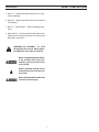
PROTECT YOURSELF AND OTHERS --
Some welding, cutting, and gouging
processes are noisy and require ear
protection. The arc, like the sun, emits
ultraviolet (UV) and other radiation
and can injure skin and eyes. Hot metal can cause
burns. Training in the proper use of the processes
and equipment is essential to prevent accidents.
Therefore:
1. Always wear safety glasses with side shields in any
work area, even if welding helmets, face shields, and
goggles are also required.
2. Use a face shield tted with the correct lter and
cover plates to protect your eyes, face, neck, and
ears from sparks and rays of the arc when operating
or observing operations. Warn bystanders not to
watch the arc and not to expose themselves to the
rays of the electric-arc or hot metal.
3. Wear ameproof gauntlet type gloves, heavy long-
sleeve shirt, cuess trousers, high-topped shoes,
and a welding helmet or cap for hair protection, to
protect against arc rays and hot sparks or hot metal.
A ameproof apron may also be desirable as protec-
tion against radiated heat and sparks.
4. Hot sparks or metal can lodge in rolled up sleeves,
trouser cus, or pockets. Sleeves and collars should
be kept buttoned, and open pockets eliminated from
the front of clothing.
5. Protect other personnel from arc rays and hot
sparks with a suitable non-ammable partition or
curtains.
6. Use goggles over safety glasses when chipping slag
or grinding. Chipped slag may be hot and can y far.
Bystanders should also wear goggles over safety
glasses.
FIRES AND EXPLOSIONS -- Heat from
ames and arcs can start res. Hot
slag or sparks can also cause res and
explosions. Therefore:
1. Remove all combustible materials well away from
the work area or cover the materials with a protec-
tive non-ammable covering. Combustible materials
include wood, cloth, sawdust, liquid and gas fuels,
solvents, paints and coatings, paper, etc.
2. Hot sparks or hot metal can fall through cracks or
crevices in oors or wall openings and cause a hid-
den smoldering re or res on the oor below. Make
certain that such openings are protected from hot
sparks and metal.“
3. Do not weld, cut or perform other hot work until the
workpiece has been completely cleaned so that there
are no substances on the workpiece which might
produce ammable or toxic vapors. Do not do hot
work on closed containers. They may explode.
4. Have re extinguishing equipment handy for instant
use, such as a garden hose, water pail, sand bucket,
or portable re extinguisher. Be sure you are trained
in its use.
5. Do not use equipment beyond its ratings. For ex-
ample, overloaded welding cable can overheat and
create a re hazard.
6. After completing operations, inspect the work area
to make certain there are no hot sparks or hot metal
which could cause a later re. Use re watchers when
necessary.
7. For additional information, refer to NFPA Standard
51B, "Fire Prevention in Use of Cutting and Welding
Processes", available from the National Fire Protec-
tion Association, Batterymarch Park, Quincy, MA
02269.
ELECTRICAL SHOCK -- Contact with
live electrical parts and ground can
cause severe injury or death. DO NOT
use AC welding current in damp areas,
if movement is conned, or if there is
danger of falling.

6
SECTION 1 SAFETY PRECAUTIONS
1. Be sure the power source frame (chassis) is con-
nected to the ground system of the input power.
2. Connect the workpiece to a good electrical
ground.
3. Connect the work cable to the workpiece. A poor
or missing connection can expose you or others
to a fatal shock.
4. Use well-maintained equipment. Replace worn or
damaged cables.
5. Keep everything dry, including clothing, work
area, cables, torch/electrode holder, and power
source.
6. Make sure that all parts of your body are insulated
from work and from ground.
7. Do not stand directly on metal or the earth while
working in tight quarters or a damp area; stand
on dry boards or an insulating platform and wear
rubber-soled shoes.
8. Put on dry, hole-free gloves before turning on the
power.
9. Turn o the power before removing your gloves.
10. Refer to ANSI/ASC Standard Z49.1 (listed on
next page) for specic grounding recommenda-
tions. Do not mistake the work lead for a ground
cable.
ELECTRIC AND MAGNETIC FIELDS
— May be dangerous. Electric cur-
rent owing through any conduc-
tor causes localized Electric and
Magnetic Fields (EMF). Welding and
cutting current creates EMF around welding cables
and welding machines. Therefore:
1. Welders having pacemakers should consult their
physician before welding. EMF may interfere with
some pacemakers.
2. Exposure to EMF may have other health eects which
are unknown.
3. Welders should use the following procedures to
minimize exposure to EMF:
A. Route the electrode and work cables together.
Secure them with tape when possible.
B. Never coil the torch or work cable around your
body.
C. Do not place your body between the torch and
work cables. Route cables on the same side of
your body.
D. Connect the work cable to the workpiece as close
as possible to the area being welded.
E. Keep welding power source and cables as far
away from your body as possible.
FUMES AND GASES -- Fumes and
gases, can cause discomfort or harm,
particularly in conned spaces. Do
not breathe fumes and gases. Shield-
ing gases can cause asphyxiation.
Therefore:
1. Always provide adequate ventilation in the work area
by natural or mechanical means. Do not weld, cut, or
gouge on materials such as galvanized steel, stain-
less steel, copper, zinc, lead, beryllium, or cadmium
unless positive mechanical ventilation is provided.
Do not breathe fumes from these materials.
2. Do not operate near degreasing and spraying opera-
tions. The heat or arc rays can react with chlorinated
hydrocarbon vapors to form phosgene, a highly
toxic gas, and other irritant gases.
3. If you develop momentary eye, nose, or throat ir-
ritation while operating, this is an indication that
ventilation is not adequate. Stop work and take
necessary steps to improve ventilation in the work
area. Do not continue to operate if physical discom-
fort persists.
4. Refer to ANSI/ASC Standard Z49.1 (see listing below)
for specic ventilation recommendations.

7
SECTION 1 SAFETY PRECAUTIONS
5. WARNING: This product, when used for welding
or cutting, produces fumes or gases
which contain chemicals known to
the State of California to cause birth
defects and, in some cases, cancer.
(California Health & Safety Code
§25249.5 et seq.)
CYLINDER HANDLING -- Cylinders,
if mishandled, can rupture and vio-
lently release gas. Sudden rupture
of cylinder, valve, or relief device can
injure or kill. Therefore:
1. Use the proper gas for the process and use the
proper pressure reducing regulator designed to
operate from the compressed gas cylinder. Do not
use adaptors. Maintain hoses and ttings in good
condition. Follow manufacturer's operating instruc-
tions for mounting regulator to a compressed gas
cylinder.
2. Always secure cylinders in an upright position by
chain or strap to suitable hand trucks, undercar-
riages, benches, walls, post, or racks. Never secure
cylinders to work tables or xtures where they may
become part of an electrical circuit.
3. When not in use, keep cylinder valves closed. Have
valve protection cap in place if regulator is not con-
nected. Secure and move cylinders by using suitable
hand trucks. Avoid rough handling of cylinders.
4. Locate cylinders away from heat, sparks, and ames.
Never strike an arc on a cylinder.
5. For additional information, refer to CGA Standard P-1,
"Precautions for Safe Handling of Compressed Gases
in Cylinders", which is available from Compressed
Gas Association, 1235 Jeerson Davis Highway,
Arlington, VA 22202.
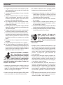
EQUIPMENT MAINTENANCE -- Faulty or
improperly maintained equipment can
cause injury or death. Therefore:
1. Always have qualied personnel perform the instal-
lation, troubleshooting, and maintenance work.
Do not perform any electrical work unless you are
qualied to perform such work.
2. Before performing any maintenance work inside a
power source, disconnect the power source from
the incoming electrical power.
3. Maintain cables, grounding wire, connections, power
cord, and power supply in safe working order. Do
not operate any equipment in faulty condition.
4. Do not abuse any equipment or accessories. Keep
equipment away from heat sources such as furnaces,
wet conditions such as water puddles, oil or grease,
corrosive atmospheres and inclement weather.
5. Keep all safety devices and cabinet covers in position
and in good repair.
6. Use equipment only for its intended purpose. Do
not modify it in any manner.
ADDITIONAL SAFETY INFORMATION -- For
more information on safe practices for
electric arc welding and cutting equip-
ment, ask your supplier for a copy of
"Precautions and Safe Practices for Arc
Welding, Cutting and Gouging", Form
52-529.
The following publications, which are available from
the American Welding Society, 550 N.W. LeJuene Road,
Miami, FL 33126, are recommended to you:
1. ANSI/ASC Z49.1 - "Safety in Welding and Cutting"
2. AWS C5.1 - "Recommended Practices for Plasma Arc
Welding"
3. AWS C5.2 - "Recommended Practices for Plasma Arc
Cutting"
4. AWS C5.3 - "Recommended Practices for Air Carbon
Arc Gouging and Cutting"

8
SECTION 1 SAFETY PRECAUTIONS
5. AWS C5.5 - "Recommended Practices for Gas Tung-
sten Arc Welding“
6. AWS C5.6 - "Recommended Practices for Gas Metal
Arc Welding"“
7. AWS SP - "Safe Practices" - Reprint, Welding Hand-
book.
8. ANSI/AWS F4.1, "Recommended Safe Practices for
Welding and Cutting of Containers That Have Held
Hazardous Substances."
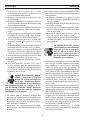
MEANING OF SYMBOLS - As used
throughout this manual: Means Atten-
tion! Be Alert! Your safety is involved.
Means immediate hazards which,
if not avoided, will result in im-
mediate, serious personal injury
or loss of life.
Means potential hazards which
could result in personal injury or
loss of life.
Means hazards which could result
in minor personal injury.
Page is loading ...
Page is loading ...
Page is loading ...
Page is loading ...
Page is loading ...
Page is loading ...
Page is loading ...
Page is loading ...

17
2.1 DESCRIPTION
This manual has been prepared for use by an experienced operator. It provides information to familiarize the operator with
the design, installation and operation of the MultiPower 460 Pulse Panel. DO NOT attempt to install or operate this pulse
option until you have read and fully understood these instructions. The information presented here should be given careful
consideration to ensure proper installation and optimum weld performance.
The MultiPower 460 Pulse kit upgrades a standard MultiPower 460 power source to a multi-process power source designed
for Mig short circuiting, spray and pulse spray transfer (GMAW), ux core (FCAW), Tig (GTAW), and stick (SMAW) welding and
air carbon arc cutting/gouging (CAC-A) applications. The following instruction assumes you are familiar with the standard
MultiPower 460 operation and set-up. These instruction are intended to supplement the original MultiPower 460 instruction
book received when the power source was installed.
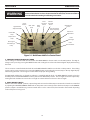
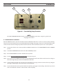
2.2 PULSE CONTROL PANEL DESCRIPTION (Refer to Figure 2-1)
1. FAULT LAMP
The RED fault light on the MultiPower 460 Pulse front panel indicates a problem with set-up parameters. A "Steady" light
"On" indicates there is no program for the material and wire diameter selected. A "Blinking" light indicates the wire feed
speed is out of the recommended range.
2. TEMPERATURE LAMP
The TEMP lamp illuminates if an over temperature condition occurs within the MultiPower 460 Pulse power source. This
condition may be caused by excessive duty cycle or over-current conditions. When an over temperature condition occurs,
the welding output is turned o and the unit must be allowed to cool. The machine will automatically reset when the
temperature falls to a safe level.
3. PROCESS SELECTOR SWITCH
The three position process selector switch is located in the upper right-hand corner of the control panel. The process selec-
tor switch position provides the visual indication of which weld process (Mig, Tig or stick) has been selected.
4. DIGITAL DISPLAYS WFS, AMPS & VOLTS
The digital displays located on the left side of the control panel are multifunctional depending on the welding process being
used. The top display reads wire feed speed in inches per minute in the MIG PRESET mode and welding current (in amps)
in the TIG and STICK PRESET mode. During welding both displays indicate average welding current (amps) and average
welding voltage.
The wire feed speed is displayed in inches per minute (IPM) in the top display when the PRESET button is pressed and the
wire speed adjustment knob on the wire feeder is turned. The WFS LED beside the top display will light when the display
is showing wire feed speed.
SECTION 2 DESCRIPTION
2.0 Description

18
Digital Meters
Amps/Volts/WFS
Power “ON”
Lamp
Temperature
Lamp
No Program
Out of Range
Lamp
WFS - IPM
Lamp
Amps
Lamp
Preset
Button
Weld Process
Switch
Inductance
Adjustment
Current Voltage
Pulse Frequency
Figure 2-1. MultiPower 460 Pulse Control Panel
Pulse
Standard
Switch
Remote
Standard
Switch
Pulse
Wire Type
Pulse
Wire Diameter
ELECTRIC SHOCK CAN KILL! Make sure that all primary input power to the power
source and wire feeder has been disconnected at the wall (line) disconnect switch or
circuit breaker before making the following connections.
5. VOLTAGE/CURRENT/TRIM ADJUST KNOB
The arc voltage is controlled with this knob when the WELD PROCESS selector switch is in the MIG position. The Mig arc
voltage can be preset by pressing the PRESET button and reading the arc volts in the bottom digital display while turning
this knob.
The arc current is controlled with this knob when the WELD PROCESS SWITCH is in the TIG or STICK position. The welding
current can be preset in amperes by pressing the PRESET button and reading the current (amps) in the top digital display
while turning this knob. The average arc current will be displayed during welding.
For MIG PULSE welding, the arc length (arc voltage) is controlled with this knob. The WELD PROCESS switch is placed in
the MIG position and the MIG PROCESS switch is placed in the MIG PULSE position. The arc length can then be adjusted by
turning the knob clockwise to increase the arc length or counterclockwise to decrease the arc length.
6. PANEL/REMOTE SWITCH
With this switch in the PANEL position, output voltage in the CV mode and the output current in the CC mode are controlled
by adjusting the VOLTAGE/CURRENT/TRIM knob on the power source control panel to the desired output. In the REMOTE
position, output is controlled using a remote control device such as a wire feeder, hand control or foot control depending
on the weld process being used.
WARNING
SECTION 2 DESCRIPTION

19
SECTION 2 DESCRIPTION
7. INDUCTANCE TRIM
This control is used only in the STANDARD MIG process mode and is deactivated in the TIG, STICK and MIG PULSE mode.
Inductance is used to optimize short circuiting arc performance by changing the current rise and fall time of each short circuit.
This results in improved spatter control, weld bead wetting and arc stability. The short circuiting Mig arc performance will
change from a high short circuit frequency, fast reacting arc, to a lower short circuit frequency, soft and less spattering arc
as the dial is turned clockwise. The optimized arc performances will vary depending on shielding gas, wire type and wire
diameter. The operator can adjust this control to optimize welding characteristics.
8. MIG STANDARD/PULSE SWITCH
This switch enables the Mig pulse operation mode. When this switch is in the MIG PULSE position, the pulse parameters are
determined by the WIRE TYPE and WIRE DIAMETER position on the PULSE SELECTION switches.
9. PULSE SELECTION SWITCHES
WIRE TYPE
Use this switch to select the WIRE TYPE installed on the wire feeder. The position of this switch and the WIRE DIAMETER
switch selects the pulse parameters to be used during welding in the Mig pulse mode.
WIRE DIAMETER
Use this switch to select the WIRE DIAMETER installed on the wire feeder. The position of this switch and the WIRE TYPE
switch selects the pulse parameters to be used during welding in the Mig pulse mode.
Page is loading ...

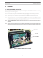
21
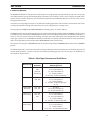
Panel Screws
Panel Harness Plug
Figure 3-1. MultiPower 460 Pulse Harness Connection
SECTION 3 INSTALLATION
3.0 Installation
3.1 PULSE CONTROL PANEL INSTALLATION
The standard MultiPower 460 control panel are easily removed and replaced with the MultiPower 460 Pulse version using
the following procedure. Refer to Figure 3-1.
Step 1. Disconnect ALL primary power from the MultiPower 460 by unplugging the unit or removing the line fuses.
Step 2. Remove the four screws (one at each corner) holding the standard MultiPower 460 control panel in place.
Step 3. Tilt the panel forward and disconnect the wiring harness plug connector, remove the meter PCB from the panel
leaving the wire harness connected. Remove the control panel from the PC board compartment. Do not discard
this panel, it can be used as a spare replacement panel if problems arise.
Step 4 Connect the NEW MultiPower 460 Pulse control panel harness plug to the power source harness and install the
meter PCB.
Step 5. Carefully position the panel harness plug to the left side of the heatsinks on the main PCB, position the control
panel over the PC board compartment and secure with the mounting screws removed from the standard control
panel.
Heatsinks

22
SECTION 3 INSTALLATION

23
SECTION 4 OPERATION
4.0 Operation
4.1 OPERATION
A. WIRE FEEDER COMPATIBILITY
The MultiPower 460 Pulse power source can be used with several wire feeders. The model wire feeder being used will de-
termine the setup method and operator interface. The position of the REMOTE/PANEL switch determines the location of
the voltage preset and PULSE FREQUENCY locations. The wire feed speed is always set from the wire feeder using the wire
speed knob on the feeder control panel in the PULSE mode. To see the approximate wire feed speed, which matches the
PULSE FREQUENCY selected, press the PRESET button on the MultiPower 460 control panel.
B. DIGITAL DISPLAY METERS
The digital displays located on the left side of the control panel are multifunctional depending on the welding process be-
ing used.
C. MIG WELDING
In the standard MIG process mode, the digital display will read preset arc volts when the PRESET button is pressed. Once
welding begins, the displays will show average welding current and volts in the top and bottom display, respectively. The
displays have a “HOLD” circuit that retains the welding conditions. After welding stops, the display will continue to show
the last welding current and voltage sampled for 10 seconds, then returns to “0”.

24
2
3
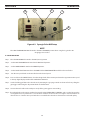
Figure 4-1. Standard Mig Setup Procedure
4
1
NOTE:
Place MIG STANDARD/MIG PULSE switch in the MIG STANDARD position when using the Tig, Stick or Arc
Gouging process modes.
D. STANDARD MIG CV WELDING
When the PROCESS switch is placed in the MIG position the MultiPower 460 Pulse is set for CV (constant voltage) welding.
The power source will output open circuit voltage (OCV) when the Mig Gun trigger is depressed. The following procedure
assumes the wire feed and voltage adjustments will be made from the wire feeder front panel and a remote pendant.
Step 1. Connect wire feeder and a remote pendant to MultiPower 460 Pulse and set PANEL/REMOTE switch to REMOTE
position.
Step 2. Set the MIG STANDARD/PULSE switch to the MIG STANDARD position.
Step 3. Place the WELD PROCESS switch in the MIG (center) position.
Step 4. Turn the wire speed control on the wire feeder to the desired speed.
Step 5. Press and release the PRESET button then turn the VOLTAGE knob of the wire feeder to the desired arc voltage in
the bottom digital display window of the MultiPower 460 Pulse.
Step 6. Set the shielding gas ow to the desired rate by activating the gas purge switch on the wire feeder or pulling the
gun trigger and turning the adjustment knob on the Flowmeter.
Step 7. Connect the work cable to the part to be welded and pull the gun trigger to start welding. Trim the wire speed and
volts as needed for the desired arc characteristics and weld quality.
SECTION 4 OPERATION

25
E. MIG PULSE WELDING
The MultiPower 460 Pulse is designed to provide simple to use, high quality, preprogrammed synergic and non-synergic
pulsed Mig welding. Synergic pulsed Mig welding means that pulse parameters (such as pulse height, pulse width, back-
ground current and pulse frequency) are automatically adjusted by the MultiPower 460 Pulse as the wire feed speed is
changed by the operator.
A unique non-synergic Mig pulse mode is also oered for welding applications and wire feeder combinations that cannot
use the preprogrammed synergic pulse data. This pulse panel is shipped in non-synergic mode.
The preprogrammed WIRE TYPES, WIRE DIAMETERS and shielding gases are listed in Table 4-1.
The TRIM allows the operator to ne tune the pulse arc length and optimize the welding. When the PROCESS switch is placed
in the MIG position and the MIG STANDARD/PULSE switch is place in the MIG PULSE position, the MultiPower 460 Pulse is
set for CC over CC (constant current) pulse welding. The power source will output open circuit voltage (OCV) when the Mig
Gun trigger is depressed. The MultiPower 460 Pulse provides Pulse Frequency control from either the remote pendant or
power source depending on the position of the PANEL/REMOTE switch characteristics.
The operator can change to STANDARD MIG (CV) by simply moving the MIG STANDARD/PULSE switch to the STANDARD
position.
The following procedure assumes the wire feed and voltage adjustments will be made from the wire feeder front panel and
remote control paendant. See Table 4-1 for the recommended shielding gases for each wire alloy type. Set the owrate at
30 to 40 cfh for argon mixtures.
SECTION 4 OPERATION
Table 4-1. Wire Types, Diameter and Shield Gases
Material Type
Wire
Diameters
Shielding Gas
(AWS Designation)
Carbon Steel .035, .045 soft,
.045,
.045 med,
.045 strong
Ar - 5% CO2 (SG-AC-5
Ar - 8% CO2 (SG-AC-8)
Ar - 10% CO2 (SG-AC-10)
Ar - 2% O2 (SG-AO-2)
Ar - 8% CO2 - 2% O2 (SG-ACO-8/2)
Stainless Steel .035, .040,
.045, .062
Ar -2% CO2 (SG-AC-2)
Ar - 8% CO2 (SG-AC-8)
Ar - 2% O2 (SG-AO-2)
Ar - 8% CO2 - 2% O2 (SG-ACO-8/2)
Ar - He
4000 & 5000
Aluminum
.035, .040,
3/64, .062
Ar ( SG-A)
Ar - He 25% (SG-AHe-25)
Ar - He 50% (SG-Ahe-50)
Metal Core
Carbon Steel
.035, .040,
.045, .052,
.062
Ar - 5% CO2 (SG-AC-5)
Ar - 8% CO2 (SG-AC-8)
Ar - 10% CO2 (SG-AC-10)
Ar - 2% O2 (SG-AO-2)
Ar - 8% CO2 - 2% O2 (SG-ACO-8/2)
Metal Core
Carbon Steel
.045, .062 Ar -2% CO2 (SG-AC-2)
Ar - 8% CO2 (SG-AC-8)
Ar - 1% O2 (SG-AO-1)
Ar - He 50% - 2% CO2 (SG-AHeC-50/2)

26
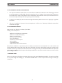
F. PULSE MIG SETUP
Step 1. Place the WELD PROCESS switch in the MIG (center) position
Step 2. Set the MIG STANDARD/PULSE switch to the MIG PULSE position.
Step 3. Set the PANEL/REMOTE switch to the REMOTE position.
Step 4. Set the PULSE SELECTION switches to the WIRE TYPE and WIRE DIAMETER installed on the wire feeder.
Step 5. Turn the wire speed knob on the wire feeder to the desired speed.
Step 6. Press and release the PRESET button. Turn the voltage knob of the remote pendant to the approximate wire speed
in the top digital display window of the MultiPower 460 Pulse.
Step 7. Set the shielding gas ow to the desired rate by activating the gas purge switch on the wire feeder or pulling the
gun trigger and turning the adjustment knob on the owmeter.
Step 8. Connect the work cable to the workpiece and pull the gun trigger to start welding.
Step 9. The voltage knob on the remote pendant becomes the PULSE FREQUENCY CONTROL and is used to ne tune the
arc length for best arc performance. Turn the knob clockwise to increase the arc length or counterclockwise to
decrease the arc. Trim the wire speed and volts as needed for the desired arc characteristics and weld quality.
1
2
4
3
Figure 4-2. Synergic Pulse MIG Setup
5
NOTE
Place MIG STANDARD/MIG PULSE switch in the MIG STANDARD position when using the Tig, Stick or Arc
Gouging process modes.
SECTION 4 OPERATION

27
G. PULSE PROCESS CONTROL AND OPERATION
1. Use a tip-to-work distance (TTW) of 3/8" to 5/8". This refers to the distance between the end of the Mig gun contact
tip and the workpiece or weld puddle. The pulse control panel has an '"adaptive" characteristic which compensates
for normal changes in tip-to-work distance. This is helpful when a long stick out is necessary to reach into corners or
when transversing the weld puddle during weaving of vertical welding.
2. For the best arc stability, keep the arc on the front edge of the molten puddle and use a 5 to 10 degree gun angle from
the vertical.
3. If the arc is "crackling" or if spatter is excessive lengthen the arc. If the arc is "uttering" or dicult to control then
shorten the arc length.
H. PULSE MIG ARC STABILITY
Many variables can aect the arc stability of pulse MIG
welding. Some examples are:
Dierences in shielding gas compositions
Dierences in weld wire chemistry
Water vs. air cooled guns
Base metal surface condition
Tip-to work distance
Variations on wire feed speed
Wire feedability
Long welding cables
High resistance cables and connections
When adverse conditions are present, the pulse arc stability is sometimes less than desirable. The arc will "crackle" and
produce higher than normal spatter levels. This occurs when high resistances in the welding circuit cause changes pulse
waveform and average current levels or the wire feed rate is varying excessively. The OUTPUT CONTROL knob adjusts the
pulse frequency to accommodate changes in the welding equipment set-up and base material variations to achieve a stable
pulse welding condition.
I. SHIELDING GASES
Table 4-1 lists the types of shielding gas mixtures that can be used with the MultiPower 460 Pulse. The wire burn-o rate
can vary with changes in shielding gas. The OUTPUT CONTROL knob is used to compensate for changes in shield gas
composition.
SECTION 4 OPERATION

28
J. NON-SYNERGIC PULSE OPERATION
The MultiPower 460 Pulse has the unique ability to Pulse MIG weld in the NON-SYNERGIC mode. Non-synergic operation
means the pulse parameters can be selected by choosing the WIRE TYPE, WIRE DIAMETER, and presetting a WIRE FEED SPEED
on the MultiPower 460 Pulse panel. The pulse frequency or arc length (OUTPUT CONTROL) is controlled by the OUTPUT
CONTROL knob. The OUTPUT CONTROL knob is adjustable from the minimum to maximum pulse frequency. By using a
combination of adjusting the wire feed speed on the wire feeder and OUTPUT CONTROL setting on the MultiPower 460
Pulse, the pulse Mig welding arc can be tuned in and stabilized.
The selectable pulse parameters are any combination of WIRE TYPE or WIRE DIAMETER selected using the PULSE SELECTION
switches. Not all combinations will produce acceptable pulse characteristics but by using the pulse tables provided in this
manual, reasonable pulse combinations can be selected for trial. This will take some trial and error but the added exibility
and expanded pulse range of the non-synergic mode can be benecial for many welding applications.
There are several unique advantages to Non Synergic pulse mig welding. The Non -Synergic mode of operation permits
pulse welding when:
1. A wire feeder without tachometer feedback is used.
2. An "O the Arc" wire feeder is used
3. The Mig wire type or diameter installed on the wire feeder does not have a pulse synergic line available..
4. Pulse arc characteristics other than those preprogrammed are desired.
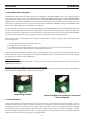
To take advantage of the MultiPower 460 Pulse Non-Synergic mode, it is necessary to reposition a jumper plug and/or con-
nector in the main control panel wiring harness. Remove the MultiPower 460 control panel and locate the jumper plug in
the wiring harness in the PC board compartment.
Jumper Plug Installed
Synergic Mode - Pulse circuitry is looking for a 1 volt per 100 inches per minute signal to determine the pulse parameters
required to make the weld.
Jumper Plug Removed and Harness connected (Factory Shipped)
Non-Synergic Mode - The pulse parameters are determined by the position of the pulse selection switches, the MultiPower
460 Pulse OUTPUT CONTROL knob and Wire Feed Speed preset.
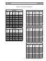
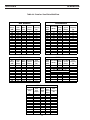
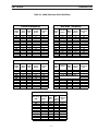
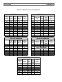
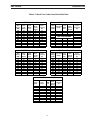
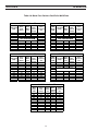
K. PULSE PARAMETERS
Tables 4-3 through 4-8 list the approximate pulse weld parameters for each material and diameter available. These are
provided for general reference only. Actual pulse parameters can vary with the equipment set-up, welding application and
shielding gas being used. The wire feed speed ranges shown in the tables are the same as programmed into the MultiP-
ower 460 Pulse program. Attempting to weld outside of the suggested speed ranges will result in a "blinking" in synergic
line indicator light on the UltraPulse front panel. A "steady" light lite on the panel indicates the wire material and diameter
combination selected does not have any pulse data programmed.
Figure 4-3.
Jumper Plug Installed
Figure 4-4.
Jumper Plug Removed and Harness Connected
(Factory Shipped)
SECTION 4 OPERATION

29
Table 4-3. Carbon Steel Pulse Weld Data
SECTION 4 OPERATION
20
SECTION 5 OPERATION
Table 5-3 Carbon Steel Pulse Weld Data
.035 Steel .040 Steel
WFS
Range
(IPM)
Pulse
Peak
(Amps)
Pulse
Width
(ms)
Pulse Back
-
ground
(Amps)
Pulse
Frequency
(Hz)
WFS
Range
(IPM)
Pulse Peak
(Amps)
Pulse
Width
(ms)
Pulse Back
-
ground
(Amps)
Pulse
Frequency
(Hz)
75 312 1.70 19 52 75 304 2.40 25 42
125 318 1.70 26 70 125 318 2.40 34 58
175 325 1.70 32 87 175 332 2.40 44 75
225 331 1.70 39 105 225 346 2.40 53 92
275 337 1.70 46 123 275 360 2.40 62 108
325 343 1.70 52 141 325 374 2.40 71 125
375 350 1.70 59 158 375 388 2.40 80 141
425 356 1.70 65 176 425 402 2.40 89 158
475 362 1.70 72 194 475 416 2.40 98 174
525 368 1.70 79 212 525 430 2.40 107 191
575 375 1.70 85 229 575 444 2.40 116 207
625 381 1.70 92 247 625 458 2.40 125 224
675 387 1.70 98 265 675 472 2.40 135 241
725
394 1.70 105 283
725
486 2.40 144 257
.045 Steel .052 Steel
WFS
Range
(IPM)
Pulse
Peak
(Amps)
Pulse
Width
(ms)
Pulse Back
-
ground
(Amps)
Pulse
Frequency
(Hz)
WFS
Range
(IPM)
Pulse Peak
(Amps)
Pulse
Width
(ms)
Pulse Back
-
ground
(Amps)
Pulse
Frequency
(Hz)
125 441 2.20 45 64 100 400 2.50 80 56
175 451 2.20 56 85 175 400 2.50 80 93
225 461 2.20 68 106 250 400 2.50 80 131
275 471 2.20 79 128 325 400 2.50 80 169
325 481 2.20 90 149 400 400 2.50 80 207
375
491 2.20 101 171
475
400 2.50 80 244
425 501 2.20 113 192 550 400 2.50 80 282
475 511 2.20 124 213 625 400 2.50 80 320
525 521 2.20 135 235 700 400 2.50 80 358
575 531 2.20 146 256
1/16 Steel
WFS
Range
(IPM)
Pulse
Peak
(Amps)
Pulse
Width
(ms)
Pulse
Back-
ground
(Amps)
Pulse
Frequency
(Hz)
50 518 2.50 45 40
100 524 2.50 80 71
150 529 2.50 114 103
200 534 2.50 148 134
250 540 2.50 182 166
300 545 2.50 216 197
350
550 2.50 250 228
400 556 2.50 284 260
.045 soft
WFS
Range
(IPM)
Pulse
Peak
(Amps)
Pulse
Width
(ms)
Pulse Back-
ground
(Amps)
Pulse
Frequen-
cy (Hz)
75 500 2.00 20 65
125 500 2.00 20 95
175 500 2.00 20 125
225 500 2.00 20 155
275 500 2.00 20 185
325 500 2.00 20 215
375 500 2.00 20 245
425 500 2.00 20 275
475 500 2.00 20 305
525 500 2.00 20 335
.045 med
WFS
Range
(IPM)
Pulse
Peak
(Amps)
Pulse
Width
(ms)
Pulse Back-
ground
(Amps)
Pulse
Frequen-
cy (Hz)
75 430 2.20 20 65
125 430 2.20 20 95
175 430 2.20 20 125
225 430 2.20 20 155
275 430 2.20 20 185
325 430 2.20 20 215
375 430 2.20 20 245
425 430 2.20 20 275
475 430 2.20 20 305
525 430 2.20 20 335
.045 strong
WFS
Range
(IPM)
Pulse
Peak
(Amps)
Pulse
Width
(ms)
Pulse Back-
ground
(Amps)
Pulse
Frequen-
cy (Hz)
75 430 1.80 20 75
125 430 1.80 20 110
175 430 1.80 20 145
225 430 1.80 20 180
275 430 1.80 20 215
325 430 1.80 20 250
375 430 1.80 20 285
425 430 1.80 20 320
475 430 1.80 20 355
525 430 1.80 20 390
Page is loading ...
Page is loading ...
Page is loading ...
Page is loading ...
Page is loading ...
Page is loading ...
Page is loading ...
Page is loading ...
Page is loading ...
-
 1
1
-
 2
2
-
 3
3
-
 4
4
-
 5
5
-
 6
6
-
 7
7
-
 8
8
-
 9
9
-
 10
10
-
 11
11
-
 12
12
-
 13
13
-
 14
14
-
 15
15
-
 16
16
-
 17
17
-
 18
18
-
 19
19
-
 20
20
-
 21
21
-
 22
22
-
 23
23
-
 24
24
-
 25
25
-
 26
26
-
 27
27
-
 28
28
-
 29
29
-
 30
30
-
 31
31
-
 32
32
-
 33
33
-
 34
34
-
 35
35
-
 36
36
-
 37
37
-
 38
38


ESAB MultiPower 460 Pulse Upgrade Kit Installation guide
- Category
- Welding System
- Type
- Installation guide
Ask a question and I''ll find the answer in the document
Finding information in a document is now easier with AI