Weil-McLain GV Owner's manual

Category
Fireplaces
Type
Owner's manual

Weil-McLain GV is a high-efficiency water boiler series that combines advanced technology with user-friendly features for reliable and efficient home heating. Its innovative design offers numerous benefits, including:

  • Efficient Heating: GV boilers utilize a unique heat exchanger system to extract maximum heat from the combustion process, resulting in exceptional energy efficiency and reduced operating costs.

  • Precise Temperature Control: Equipped with state-of-the-art controls, GV boilers provide precise temperature regulation, ensuring consistent and comfortable warmth throughout your home.

Part Number 550-110-267/0699
Special gas vent system vent and combustionSpecial gas vent system vent and combustion
Special gas vent system vent and combustion
air supplementair supplement
air supplement
Venting Supplement
FF
FF
F
asNSeal™asNSeal™
asNSeal™asNSeal™
asNSeal™
To the installer:
This Venting Supplement must only be used by a qualified installer/service
technician. Read these instructions completely before beginning the
installation. Failure to follow these instructions in proper order can cause
severe personal injury, death or substantial property damage.
To install a new vent system follow instructions in:
This Venting Supplement.
GV Boilers Vent/Air Intake Termination Assembly Instructions, if
using Weil-McLain Vent/Air Intake Termination Kit. — OR —
GV Water Boiler Series 2 & 3 Direct vent Through-roof or Through-
unused-chimney Venting Supplement
, if using Weil-McLain
Through-Roof or Through-Unused-Chimney Termination Kit.
FasNSeal™ manufacturer’s instructions supplied with vent material.
For installations above 5,500 feet use only direct vent (ducted combustion
air) when sidewall venting. All of the vertical (through-roof or through-
unused-chimney) methods in this Venting Supplement are acceptable. Can
result in severe personal injury, death or substantial property damage if
ignored.
ProTech Systems FasNSeal™ AL29-4C
®
Stainless Steel Special Gas Vent System may be
used in new installations of GV-3 through GV-6
boilers.
WW
WW
W
ater boiler — Series 3ater boiler — Series 3
ater boiler — Series 3
GOLDGOLD
GOLDGOLD
GOLD
GVGV
GVGV
GV
The following terms are used throughout this Venting Supplement to bring attention to the
presence of hazards of various risk levels or to important information concerning the life of
the product.
Indicates presence of hazards that will cause severe personal injury, death
or substantial property damage.
Indicates presence of hazards that can cause severe personal injury, death
or substantial property damage.
Indicates presence of hazards that will or can cause minor personal injury
or property damage.
Indicates special instructions on installation, operation or maintenance
that are important but not related to personal injury or property damage.
Hazard definitions
Part Number 550-110-267/0699
2
GOLD GV Water boiler — Series 3
Combustion air supply
Refer to GV Series 3 Boiler Manual for sizing free area of combustion/ventilation air openings.
All boilers experience some condensation in section assembly during start-up. Unlike most
conventional boilers, condensation is minimized in the
GV Series 3 Boiler by a built-in mixing
system, maintaining boiler return water temperature above 130
0
F, during steady state operation.
Flue gas condensate is slightly acidic. In most cases pH level is not harmful to vents or drains.
When combustion air is contaminated by vapors from products and areas, listed in Table 1
below, condensate acidic levels increase. Higher acidic levels attack many materials, including
stainless steel commonly used in high efficiency systems.
You may choose to use outside combustion air for any of the following reasons:
Installation is in an area containing contaminants listed in Table 1 below, which will
induce acidic contamination.
You want to reduce infiltration into your home through openings around windows
and doors.
Special note
To prevent potential of severe personal injury or death, check for areas and
products listed above before installing boiler. If found:
remove products permanently — OR —
provide outside combustion air
Table 1 Corrosive contaminants
Products to avoid Areas likely to have contaminants
Spray cans containing chloro/fluorocarbons Dry cleaning/laundry areas and establishments
Permanent wave solutions Swimming pools
Chlorinated waxes/cleaners Metal fabrication plants
Chlorine-based swimming pool chemicals Beauty shops
Calcium chloride used for thawing Refrigeration repair shops
Sodium chloride used for water softening Photo processing plants
Refrigerant leaks Auto body shops
Paint or varnish removers Plastic manufacturing plants
Hydrochloric acid/muriatic acid Furniture refinishing areas and establishments
Cements and glues New building construction
Antistatic fabric softeners used in clothes
dryers
Remodeling areas
Chlorine-type bleaches, detergents, and clean-
ing solvents found in household laundry rooms
Garages with workshops
Adhesives used to fasten building products and
other similar products
Part Number 550-110-267/0699
3
FasNSeal™ Venting Supplement
Vent termination
Venting method definitions
Direct vent — Uses outside combustion air with combustion
air connector piping sealed at all joints and seams. Also known as
“sealed combustion.
Non-Direct vent — Uses inside combustion air with no
combustion air connector piping.
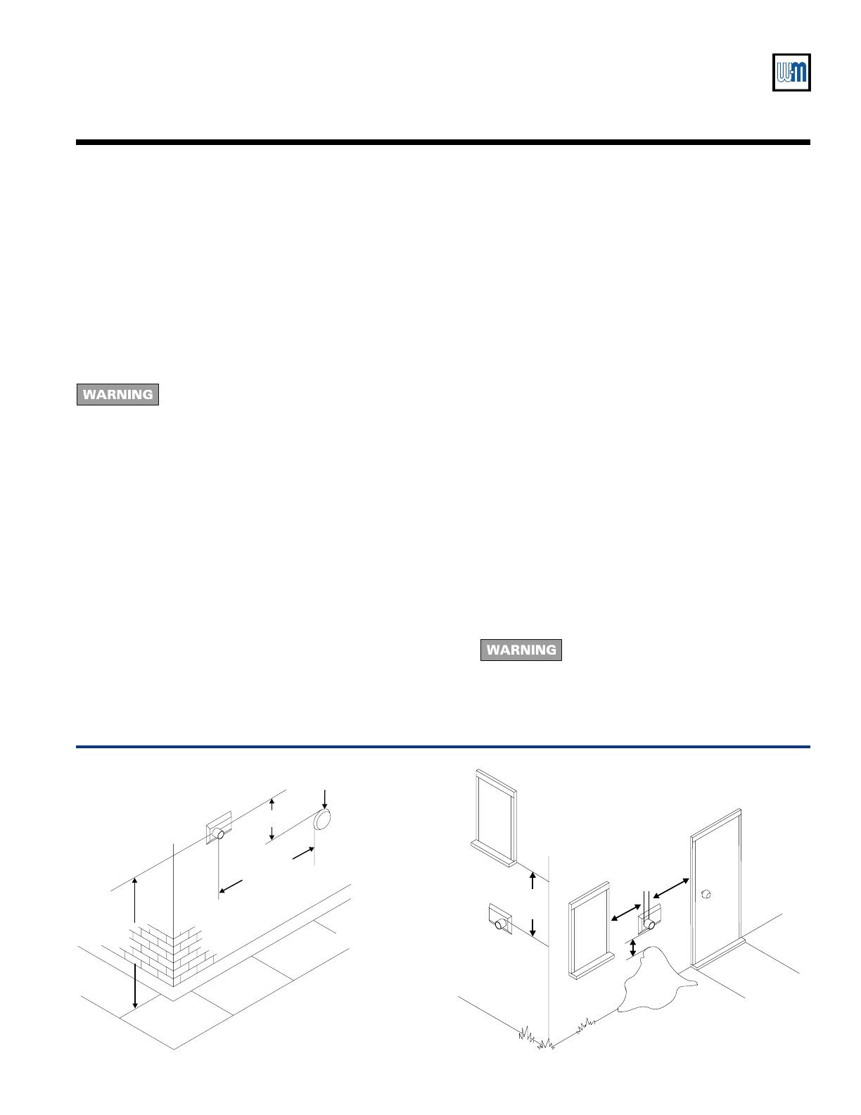
Figure 1 Vent termination locations
26707
Forced
air intake
Public Walkway
3 feet
If within 10 feet
7 feet
26708
Snow
1 foot
1 ft
1 ft
1 ft
Properly locate vent termination
Follow instructions on this page when
determining vent location to avoid possibility
of severe personal injury, death or substantial
property damage.
1. When using direct vent method — Refer to separate
instructions packed with Weil-McLain direct vent termination
kit and vent pipe manufacturer's instructions for additional
locations.
2. For location of non-direct vent vertical termination, see vent
pipe manufacturer's instructions.
3. Gases will form white plume in winter. Plume could obstruct
window view.
4. Prevailing winds could cause freezing of condensate and
water/ice buildup on building, plants or roof.
5. Locate or guard vent to prevent accidental contact by people
or pets.
6. Do not terminate vent in window well, stairwell, alcove,
courtyard, or other recessed areas.
7. Non-Direct vent installations only — Vent must terminate
more than 1 foot below or to side of all doors or windows.
See Figure 1.
8. Vent must terminate more than 1 foot above grade or
anticipated snow line. In addition, vent termination must be
at least 7 feet above public walkway and 3 feet above any forced
air intake within 10 feet. Stay well away from trees, shrubs,
and decorative items. Site conditions may dictate greater
clearances. See Figure 1.
9. Vent must terminate at least 4 feet horizontally, and in no
case above or below, unless a 4 foot horizontal distance is
maintained, from electric meters, gas meters, regulators, relief
valves, and other equipment.
10. Locate or guard vent to prevent condensate from damaging
exterior finishes.
11. Do not extend exposed vent pipe outside of building.
Condensate could freeze and block vent pipe.
12. Vent must terminate at least 6 feet away from adjacent walls.
13. Do not terminate vent closer than 5 feet below roof overhang.
14. Do not terminate vent above any door or window. Condensate
can freeze, causing ice formations.
15. Do not use existing chimney as raceway if another appliance
or fireplace is vented into or through chimney.
16. Do not connect:
Any other appliance to vent pipe.
Multiple boilers to a common vent pipe.
17. Do not wrap or insulate vent pipe and fittings.
18. Canadian installations — See CAN/CGA B149.1 or B149.2
Installation Code.
19. A gas vent extending through an exterior
wall shall not terminate adjacent to the wall
or below building extensions such as eaves,
parapets, balconies or decks. Failure to
comply could result in severe personal
injury, death or substantial property
damage.
Part Number 550-110-267/0699
4
GOLD GV Water boiler — Series 3
Installation
Pre-installation planning
1. Follow national, state, local or provincial codes or
regulations when venting GV boiler.
2. Choose vent method from those shown on page 5.
3. Select vent run components from Table 2. Table 3
states maximum vent run lengths and number of
elbows. Do not exceed data in Table 3. Longer vent
runs will slightly reduce boiler output. See Figure 2.
4. If installing with direct vent method, use same
maximum run length and number of elbows from
Description ProTech Systems, Inc.
Part Number (Note 1)
GV starter tee FSA-WEIL-GV3
GV termination coupling FSBS3
45
o
elbow
FSEL4503
90
o
elbow
FSEL9003
6" pipe FSVL603
12" pipe FSVL1203
18" pipe FSVL1803
24" pipe FSVL2403
36" pipe FSVL3603
Weil-McLain Vent/Air Intake Termination Kit 382-200-430 (Note 2)
Weil-McLain Through-Roof or Through-Unused-Chimney Termination Kit 382-200-435 (Note 2)
Notes
1. ProTech Systems, Inc. part number. Parts available through ProTech Systems, Inc.
2. Weil-McLain part number. Parts available through Weil-McLain distributor.
Table 2
Parts list
step 2. Vent and combustion air connector piping
configurations must match. Use suitable 3" material
for combustion air connector piping, such as:
Dryer vent
Galvanized steel
PVC (3" I.D.)
5. Refer to vent termination WARNING, item 19 on
page 3.
Figure 2 Boiler outputTable 3
Vent and combustion air connector piping
lengths and number of elbows
Maximum vent
length (feet)
Total number of elbows
0 2 3 4 5 6 7 8
GV-3 through GV-5 100 80 70 60 50 40 30 20
GV-6 80 60 50 40 30 20 10 --
GV-6
GV-5
GV-4
GV-3
020 40 60
80
100
Total equivalent length (feet) of vent
(from boiler to vent termination)
% Output
95
96
98
97
99
100
26700
Part Number 550-110-267/0699
5
FasNSeal™ Venting Supplement
26701
Air pipe
Vent pipe
FasNSeal
vent starter tee
Slope vent pipe downward, toward
boiler, minimum ¼” per foot.
Slope
Figure 3 GV direct vent through sidewall
(using Weil-McLain Vent/Air Intake
Termination Kit)
Figure 5 GV direct vent (using Weil-McLain
Through-Roof or Through-Unused-
Chimney Termination Kit)
26703
Slope vent
pipe
downward,
toward
boiler,
minimum ¼”
per foot.
FasNSeal
vent starter tee
Select
vent
method
Figure 7 GV non-direct vent through roof
26705
Slope vent pipe
downward, toward
boiler, minimum ¼”
per foot.
FasNSeal
vent starter tee
26704
Slope vent pipe
downward, toward
boiler, minimum
¼” per foot.
FasNSeal
vent starter tee
Figure 6 GV non-direct vent through sidewall
(using termination coupling)
(See WARNING above.)
26702
FasNSeal
vent starter tee
Slope vent pipe
downward, toward
boiler, minimum ¼”
per foot.
Slope
Figure 4 GV non-direct vent through sidewall
(using Weil-McLain Vent/Air Intake
Termination Kit)
(See WARNING above.)
For altitudes more than 5,500 feet above sea level — Do not use non-direct vent through
sidewall methods as shown in
Figures 4 and 6 below. Can cause severe personal injury, death
or substantial property damage if ignored.
Part Number 550-110-267/0699
6
GOLD GV Water boiler — Series 3
Installation — assembly
Connect vent starter
tee to boiler
Follow the instructions in the GV Series 3 Boiler Manual section
IIII
IIII
II
bb
bb
b to connect the vent
starter tee to the boiler.
Construct vent and
optional
combustion air run
Follow vent pipe manufacturer's instructions for sealing the vent. Vent and
combustion air connector piping must be sealed gas-tight to prevent
possibility of flue gas spillage and carbon monoxide emissions, resulting in
severe personal injury or death.
1. Follow
FasNSeal
manufacturer's instructions to construct vent run and for methods of
supporting vent runs.
Clean joints before sealing. See vent pipe manufacturer's instructions to clean joints.
Do not use screws.
Do not mix types or manufacturers of vent materials.
Maintain minimum one-inch clearance from combustible materials to vent pipe; 0"
clearance for noncombustible materials.
Install vent pipe with seams on top of vent runs.
If needed, male end of vent pipe may be cut to provide correct length. See vent pipe
manufacturer's instructions for use.
2. If installing with direct vent method, use instructions provided with Weil-McLain
termination kit. See Figures 3, 4 or 5 on page 5.
1. Direct vent method — follow instructions supplied in Weil-McLain Through-Roof or
Through-Unused-Chimney Termination Kit to assemble termination.
2. Non-Direct vent method (only through the roof, not through chimney):
Vent pipe must extend through roof flashing, jacket or thimble. See Figure 10.
Vent may pass through floor, inside wall or concealed space when installed according
to vent pipe manufacturer's instructions.
3. Maintain minimum one-inch clearance from combustible materials to vent pipe.
Venting through existing chimney or roof
Venting through sidewall
1. If using Weil-McLain Vent/Air Intake Termination Kit, see instructions provided in that
kit. Applies to direct (Figure 3, page 5) or non-direct vent (Figure 4, page 5) method.
2. If using non-direct method with termination coupling only, see Figures 8 and 9.
If passing through noncombustible wall, provide hole diameter large enough to insert
the pipe through. Sleeve and spacers are not required.
3. Maintain minimum one-inch clearance from combustible materials to vent pipe; 0"
clearance for noncombustible materials.
4. Refer to vent termination WARNING, item 19 on page 3.
Connect vent run to
termination
Part Number 550-110-267/0699
7
FasNSeal™ Venting Supplement
26704b
FasNSeal
vent starter tee
Figure 8 Sidewall termination installation (non-direct venting)
26709
¼" to ¾" between stop
on termination and
metal plate
4" galvanized sleeve
(through 4 " hole for
wall)
¹⁄₈
combustible
Pipe section
Metal plate
Spacers (2)
(to support and
center vent in
sleeve)
Metal plate
Pipe section
Termination coupling
Figure 9 Non-direct vent through sidewall
(using termination coupling)
Follow FasNSeal manufacturers
instructions for proper installation of vent
runs, including slope and support.
26705b
FasNSeal
vent starter tee
Figure 10 Non-Direct vent through roof
Follow FasNSeal manufacturers
instructions for proper installation of vent
runs, including slope and support.
Part Number 550-110-267/0699
8
GOLD GV Water boiler — Series 3
Weil-McLain
500 Blaine Street
Michigan City, IN 46360-2388
http://www.weil-mclain.com
Installation — assembly continued
Finish the vent
installation
Figure 11
Installation of condensate tubing
26706
FasNSeal
vent starter tee
5/8" O.D. tubing,
provided by
others
Vent
Vent and combustion air connector piping must be sealed gas-tight to
prevent possibility of flue gas spillage and carbon monoxide emissions,
resulting in severe personal injury or death.
1. See Figure 11 to install condensate tubing
(provided by others). Use condensate pump
if floor drain is higher than condensate
drain on boiler.
If required:
use a low-profile pump — OR —
set boiler on foundation (see
GV Series
3 Boiler Manual
) to allow gravity flow
to pump.
2. Size pump in gal/hr (boiler model):
0.78 (GV-3)
1.17 (GV-4)
1.56 (GV-5)
1.95 (GV-6)
Refer to pump manufacturer's instructions.
Drain to a non-freezing area.
Installing condensate tubing
If vent pipe or combustion air pipe must be reassembled
When vent pipe or combustion air pipe is disconnected for any reason, it must be reassembled
and resealed according to this Venting Supplement, the direct vent termination kit instructions
and the vent pipe manufacturer's instructions.
  • Page 1 1
  • Page 2 2
  • Page 3 3
  • Page 4 4
  • Page 5 5
  • Page 6 6
  • Page 7 7
  • Page 8 8

Weil-McLain GV Owner's manual

Category
Fireplaces
Type
Owner's manual

Weil-McLain GV is a high-efficiency water boiler series that combines advanced technology with user-friendly features for reliable and efficient home heating. Its innovative design offers numerous benefits, including:

  • Efficient Heating: GV boilers utilize a unique heat exchanger system to extract maximum heat from the combustion process, resulting in exceptional energy efficiency and reduced operating costs.

  • Precise Temperature Control: Equipped with state-of-the-art controls, GV boilers provide precise temperature regulation, ensuring consistent and comfortable warmth throughout your home.

Ask a question and I''ll find the answer in the document

Finding information in a document is now easier with AI