Page is loading ...
Page is loading ...
Page is loading ...
Page is loading ...
Page is loading ...
Page is loading ...
Page is loading ...
Page is loading ...
Page is loading ...
Page is loading ...
Page is loading ...
Page is loading ...
Page is loading ...
Page is loading ...
Page is loading ...
Page is loading ...
Page is loading ...
Page is loading ...
Page is loading ...
Page is loading ...
Page is loading ...
Page is loading ...
Page is loading ...
Page is loading ...

25
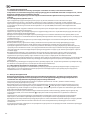
GENERAL WARNINGS
1. This manual is an integral part of the water heater. It should be preserved alongside the appliance even if
the latter is transferred to another user and/or moved to another location.
2. Carefully read this manual. It provides important information for the safe installation, use and
maintenance of the appliance.
3. The installation is the responsibility of the buyer.
4. The use of this appliance for purposes other than those specied is strictly forbidden. The manufacturer is
not to be held responsible for any damage due to failure to comply with the instructions set forth herein.
5. Installation and maintenance must be carried out by a competent person in full conformity with the
applicable legal regulations and standards, as well as the directions provided by the manufacturer.
6. Incorrect installation can cause personal injury and property damage; the manufacturer will not be held
responsible in case of incorrect installation.
7. Keep all packing material (clips, plastic bags, polystyrene foam, etc.) out of children's reach as they are
hazardous.
8. This appliance is not intended for use by persons (including children) with reduced physical, sensory, or
mental capabilities, or lack of experience and knowledge, unless they have been given supervision or
instruction concerning use of the appliance by a person responsible for their safety.
9. It is strictly forbidden to touch the appliance barefoot or with wet hands and/or feet.
10. All repairs should be carried out by a competent person only, using only original spare parts. Failure to
comply with this requirement invalidates all warranty liability on the part of the manufacturer.
11. The temperature of the hot water is adjusted by an operating thermostat that acts as a protection
against overheating.
12. Water supply must be done in accordance with paragraph “Hydraulic Connection”.
13. Electric wiring must be done in accordance with paragraph “Electrical Connection”.
14. It is strictly forbidden to modify or replace the safety valve with the other one which does not meet the
applicable requirements and standards, if it is not included in the supply.
15. No inammable items should be left in the vicinity of the appliance.
16. The water heater is a technically complex electrical appliance for household purposes.
17. Whenever electrical water heater installation involves conversion (alterations) of residential and
non-residential premises in residential buildings, installation should be performed only after relevant
permissions have been rightly obtained.

26
Do not attempt to clean the appliance without rst turning it o
and unplugging it or switching the switch o
10
11
12
Install the appliance on a solid wall that is not subjected to any
vibrations
Make all electrical connections using conductors with a suitable
section
Make sure all safety and control functions operate correctly
before start the appliance
Electrocution
Excessive noise
Fire due to overheating from electrical current passing through
undersized cables
Damage or shutdown of the appliance due to out-of-control
operation or maladjusted control system
Before handling, carry out hot water bleeding
Descale the components, in accordance with the instructions
provided on the applicable document, airing the room, wearing
protective clothing, avoid mixing dierent products, and protect
the appliance and surrounding objects
Do not use any insecticides, solvents or aggressive detergents to
clean the appliance
Personal injury from burns
Personal injury due to contact of the skin or eyes with acidic
substances, inhalation or swallowing of harmful chemical agents.
Damage to the appliance or surrounding objects due to corrosion
caused by acidic substances
Damage to the plastic and painted parts
GENERAL SAFETY NORMS
Damage to the appliance or any objects underneath it due to the
object falling o following vibrations
Personal injury from an object falling o the appliance following
vibrations.
Electrocution from a damaged cable or plug, or socket
Electrocution. Personal injury from burns due to overheated
components or wounds caused by sharp edges or protrusions
Injury from the falling appliance
Damage to the appliance or any objects underneath it due to the
appliance falling o from its place of installation
Do not climb onto the appliance
Do not leave anything on top of the appliance
Do not use the water heater with a damaged power supply cable
Do not start or stop the water heater by simply plugging it into or
out of the electricity mains. Use the power switch for this purpose
Do not open the water heater
Electrocution from live unsheathed wires under voltage
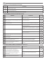
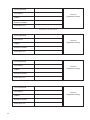
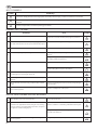
Ref. Warning Risk Symbol
1
2
3
4
5
6
7
8
9
Failure to comply with this warning implies the risk of personal injury, in some circumstances even fatal
Failure to comply with this warning implies the risk of damage to property, plants or
animals
General requirements and safe operating precautions
Symbol Meaning
KEY TO SYMBOLS
SPECIFIC SAFETY NORMS FOR THIS APPLIANCE

27
The installation and set-up of the water heater must be carried out by a competent person in conformity with the
applicable norms and sanitary standards in force and with any provisions set forth in this manual.
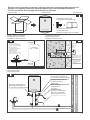
2.1. Wall-mounting
Water heater mounting is made on the main wall using brackets and fastening hooks (not included in the supply). Fastening
hooks with a diameter of at least 12 mm are recommended.
Depending on the model, you will need 2 or 4 of the fastening hooks.
The fastening must support a weight that is three times higher than the weight of the water heater lled with water.
2.1.1. It is not allowed to mount the vertical models horizontally, and horizontal models – vertically.
2.1.2. The appliance should be installed as close as possible to the point of use to limit heat dispersion.
2.1.3. Allow for a clearance of at least 50 cm around and from the ceiling – 10 cm for maintenance activities.
2.1.4. Fastening of hooks to the wall must prevent inadvertent movement of the bracket of the water heater over them. After
installation, be sure to check security of the attachment.
2.1.5. To prevent the property of the customer and/or third party from damage caused by failures of hot water supply system
it is recommended to mount the boiler in the premises provided with waterproof oor and drainage system. Also, never put
objects sensitive to water under the boiler.
Congratulations on your purchase of an electric water heater manufactured by Ariston Thermo Group. The appliance is
designed in compliance with the European standards. It is user-friendly, demonstrates great consumer properties and
durability in operation. We hope that you will be satised with its work.
Please, read this manual carefully to ensure proper installation and operation of the water heater.
1. GENERAL INFORMATION
1.1. Scope of supply and correct use
1.1.1. Water heater
1.1.2. Safety valve
1.1.3. Bracket
1.1.4. Installation and operation manual
1.1.5. Warranty certicate
1.1.6. Original packing
The appliance is designed for installation inside the buildings, in the household and utility premises. The appliance is intended
for water heating to a temperature below boiling point, with the option of the hot water’s utilization at several spots
(bathroom, kitchen, and toilet) and further maintenance of the set temperature in the automatic mode.
Water heating time depends on the volume of the tank and the power of the heating element.
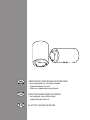
1.2. Operating principle and main elements
Main water heater elements are as follows:
1.2.1. Inner tank.
1.2.2. Thermal insulation of polyurethane foam providing minimal heat dispersion even when the water heater power is o.
1.2.3. Heating element.
1.2.4. Temperature controller which allows you to set the desired temperature of the water heating.
1.2.5. Thermostat monitoring the set temperature by on/o state control of the heating element.
1.2.6. Safety valve which is installed at the inlet of the water heater and serves to prevent the return of water to the water line
and protect the inner tank from excessive pressure.
1.2.7. Magnesium anode providing additional protection for the inner tank from corrosion.
This appliance complies with the provisions set forth in the EEC/89/336 EMC directive on electromagnetic compatibility
2. INSTALLATION
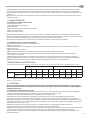
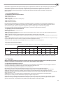
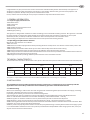
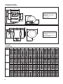
TECHNICAL CHARACTERISTICS
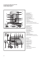
For the technical characteristics of the water heater, please refer to the data plate located near the water inlet and outlet pipes.
Ø 353 Ø 450
Volume, l 30 40 50 65 80 50 80 100 120 150
15 17 19 21 25 17 22 26 33 41
Steel
9,5 - 15 17,5 20 13 19 22 26 -
Stainless steel
Weight, kg

28
2.2. Hydraulic connection
Installation of safety valve included in the package is necessary.
Do not install any cut-o valve between the safety valve and the inlet of the tank and do not block the drain hole of
the safety valve.
Demountable connectors should be used for the water heater connection to the water supply system.
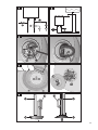
2.2.1. Standard connection (Fig. 1)
With standard connection, the heater is operated under the pressure dened by the pressure level in the main supply line.
Safety valve supplied (A in Fig. 1) must be installed on the cold water inlet of the water heater (the inlet tube is marked with
the blue collar). It is recommended to turn the safety valve no more than 3-4 turns, providing sealing with uoroplastic tape,
ax, or other water-proof sealing material.
Connect the inlet of the safety valve to the cold water line with a exible hose. If necessary, mount a cut-o valve.
Connect a pipe or a hose for hot water removal to the draw-o point to the hot water outlet of the water heater (the outlet
tube is marked with the red collar).
For easy maintenance, it is recommended to install a "T" piece union (B in Fig. 1) between the inlet and safety valve of the
water heater. This "T" piece union will help to drain water from the water heater without turning the safety valve.
To facilitate the access of air into the tank when draining water, it is recommended to install an additional "T" piece union
equipped with a cut-o valve (D in Fig. 1).
2.2.2. In the heating mode, the drain hole of the safety valve may drip water. To drain this water, a drain hose is used which
must be laid with a downslope. The temperature in the area where the drain hose is laying must not drop below 0˚C. If the
water pressure in the water line is close to the actuation pressure of the safety valve, a reducer must be installed upstream of
the safety valve. To avoid clogging of water ttings or shower heads, debris and dirt must be removed from the pipes.
2.2.3. For some models due to their design, installation of hydraulic connections, including installation of the safety valve,
may be done only with the removed plastic cover of the water heater. After installation of the hydraulic connections this
cover should be put back in place xed with its screws.
2.2.4. Connect the water heater inlet and outlet only with pipes or ttings that are able to withstand temperature in excess of
80˚С at a pressure exceeding that of the working pressure. Therefore, we advise against the use of any materials which
cannot resist such high temperatures.
2.2.5. In addition, it is recommended to connect the hose for water drain (C in Fig. 1). This hose allows directing drained
water from the water heater into the sewer or other place of your choice.
2.2.6. Connection to open tank (Fig. 2)
Water is supplied to the heater from the tank by gravity. For this purpose the tank water outlet "T" piece union supplying
water to the heater and other places must be installed higher than the water heater top. Safety valve is not necessary in this
type of connection.
2.3. Electrical connection
Electrical wiring should be done by a competent person, ensuring it complies with safety norms. The manufacturer
will not be held responsible for any damage caused by the incorrect earthling of the system or for fault defaults of
the electricity supply.
After the tank of the water heater is lled with water and the system is checked for leaks, plug in the moisture-proof electrical
plug of the water heater.
If the water heater is supplied without a power supply cable, use a cable featuring the same characteristics (type H05VV-F
3x1.5 mm², Ø 8.5 mm in diameter) for connection. The power supply cable should be threaded through the relevant hole on
the cover of the appliance and xed to the terminal board. Then every wire should be xed in place by the corresponding
screw.
The water heater must be earthed. The earth cable (of yellow-green colour and longer than that of the phases) should be
xed to the terminal marked by the symbol . Block the power supply cable using the wire clamps.
Make sure that the power supply voltage conforms to the value indicated on the data plate of the water heater. Use cables of
appropriate section.
To disconnect the unit from the electrical supply use a bipolar switch conforming to CEI-EN standards with contact opening
at least 3 mm. It is recommended to install fuses in the electricity supply circuit.
"T" piece unions, extension cords, and adapters are not allowed. Do not connect the earthling cable of the appliance to water
and gas pipes.

29
3. STARTING AND OPERATION
3.1. Commissioning
Before connect the appliance to electricity source, ll the tank up with mains water. To do this, turn on the domestic mains
tap and the hot water tap.
Once the water heater is full, the water will ow from the domestic mains tap. Visually check for water leaks from the ange
and slightly tighten it, if necessary.
Power the appliance at the switch.
3.2. Temperature control
In models equipped with external control, water temperature can be controlled by a handle connected to the thermostat in
accordance with marks.
If an appliance model does not have an external temperature controller, temperature can be set by turning the adjusting
screw of the thermostat in the range marked by the signs “+” and “-”. To do this, disconnect the water heater from the power
supply and remove the plastic cover of the appliance. It is recommended to install the controller in a position corresponding
to approximately 75% of the maximal value. In this case, the appliance is operated in economy mode, signicantly reducing
the rate of scale formation.
4. MAINTENANCE AND REPAIR WORKS
All maintenance and repair works should be carried out by a competent person only in conformity with the safety
norms and with any provisions set forth in this manual.
4.1. Water Drain
If there is a chance that the ambient temperature drops below 0°C in the room where the appliance is installed, drain water
from the water heater.
To do this, the following steps should be done:
4.1.1. Disconnect the appliance from the electrical supply;
4.1.2. Make sure that the water in the appliance is of safe temperature;
4.1.3. Turn o the tap of cold water supply to the water heater;
4.1.4. Turn on the hot water domestic mains tap for discharge of pressure inside the tank;
4.1.5. Turn on the tap (D in Fig. 1) to allow air into the tank. If it is absent, remove the supply tube to the hot water pipe of the
water heater (marked with the red collar);
4.1.6. Connect drain hose directed into the sewer to the drain cock (B in Fig. 1) and open it. If there is no a "T" piece union
with the drain cock, remove the supply pipe to the cold water inlet of the water heater (marked with the blue collar), connect
drain hose directed to the sewer to the cold water inlet;
4.1.7. After draining, make sure there is no water inside the water heater.
Freezing of water inside the water heater leads to irreversible changes and defects.
It invalidates all warranty liability on the part of the manufacturer.
4.2. Replacing internal parts
Disconnect the heater from the power supply. Remove the cover. To work with the thermostat, pull it straight out and
disconnect from the power supply.
In order to work on the heating element and the anode, the appliance must rst be emptied. For models with an autoclave
ange, remove the nut (D in Fig. 3), remove the ange holder (S in Fig. 3) and open the ange (F in Fig. 3) by pressing it inside.
Remove the ange by turning it on its axis.
For other models, remove 5 nuts (C in Fig. 4) and remove the ange (F in Fig. 4). The heating element and anode are attached
to the ange. When assembling the appliance, be sure to put the heating element, ange seal, and thermostat into their
initial position. We recommend the ange gasket is replaced every time it is removed.
Use original spare parts of the manufacturer only.
4.3. Periodical maintenance
4.3.1. Magnesium anode
The magnesium anode is an integral part of the protection system of water tank against corrosion. Given that aggressive
properties of water cause faster wear of the magnesium anode, conditions of the magnesium anode should be checked
ANNUALLY. In case of severe wear, the magnesium anode must be replaced. The warranty for water-containing tank with the
worn magnesium anode (residual volume is less than 30%) is not valid. To replace the anode, disassemble the heating
element and unscrew from the support bracket.
The magnesium anode should be replaced at least 1 in 24 months (excluding the water heater with the inner tank of stainless
steel).
The magnesium anode is a consumable item that cannot be replaced under warranty.
Following the rules of scheduled maintenance will allow you to ensure a long life of the water heater.

30
4.3.2. Safety valve
The safety valve (pressure safety device) must be inspected regularly to check that it is not clogged. Remove the limescale
deposits if necessary. If the safety valve is equipped with a lever, regular valve correct operation check procedure can be
performed with its help.
The drainage pipe of the safety valve may generate water droplets. It is not a defect; it is due to relief work function of the
valve – pressure relief that occurs when water is heated in enclosed space of the inner tank.
4.3.3. RCD (Residual Current Device)
If the appliance comes with a residual current device (RCD) located on the power cord, and then after the tank of the water
heater is lled with water and the system is checked for leaks, put in the moisture-proof electrical plug of the water heater
and do the following:
- Press “RESET” on the RCD housing, LED will be lit, indicating electricity supply.
Then press “TEST”, power will be o, as well as LED. Press “RESET” again. If the power LED lit up, it means that the appliance is
safe to use.
- If you press the “RESET” knob, but LED does not light up, contact the Technical Assistance Centre for advice by a competent
person.
4.4. Please note:
4.4.1. When you rst start the water heater, as well as on each start after disconnecting make sure that the water heater was
lled with water, and only then make its connection to the mains.
4.4.2. When the power cord is damaged it must be replaced by a special cord. This cord can be purchased at the Technical
Assistance Centre.
4.4.3. Hot water whose temperature exceeds 50°C at the user taps may immediately cause severe burns or even death.
Children, the medically fragile and the elderly are more exposed to the risk of burns.
4.4.4. Water may drip from the water heater, so do not leave valuable items and equipment under the appliance.
4.4.5. If there is a chance that the temperature drops below 0°C in the room where the appliance is installed, drain the water
from the water heater.
4.4.6. Outlets must be properly earthed.
4.4.7. While in operation, periodically clean the inner tank of the water heater. Particulate contaminants that are present in
tap water may accumulate there.
4.4.8. When there is strong scaling in the heating elements or heavy settlings, drain water, remove the heating elements, and
clean. When assembling them back follow these actions: tightening bolts should be done evenly, with no signicant force
applied, the xing support should not be tilted. Electricity supply connection can be made only after lling the water heater.
4.4.9. When the water heater is not used for a long time, shut o the cold water supply valve and disconnect the water
heater from the mains. If necessary, drain water.
4.4.10. When water pressure exceeds 5 bar, drops of water may appear in the drainage hole of the safety valve, or it may
cause a leak.
• Rare drip at the drain hole of the safety valve indicates normal operation of the heater.
• Frequent drip at the drain hole of the safety valve means that the water pressure is higher than normal. In this case, the
pressure reducer must be installed in the cold water supply pipe to reduce pressure at maximum distance from the heater.
• To remove appearing water drops, a discharge tube can be used, the end of which should be directed down to the drain,
and it should not be blocked.
4.4.11. In case of water overheating, a thermal fuse conforming to European safety standards CEI-EN breaks the electric
circuit at both leads to the heating element.
4.4.12. Traces of the thermal insulation on the top of the outer shell are the technological features of the production process
and are not defects.
4.4.13. Before making call to the service center, make sure that the problem is not related to water or power outages.
Do not try to repair the appliance under by your own forces. Technical maintenance of the appliance must be carried
out by a competent person. The data and specications indicated are not binding and the Producer reserves the
right to carry out any modications that may be required without prior notice or replacement.
This product conrms to EU Directive 2002/96/EC-EU 2002/95/EC
The symbol of the crossed waste paper basket on the appliance indicates that at the end of its working life the product
should be disposed of separately from normal domestic household rubbish, it must be disposed of at a waste disposal centre
with dedicated facilities for electric and electronic appliances or returned to the retailer when a new replacement product is
purchased.
The user is responsible for the disposal of the product at the end of its life at an appropriate waste disposal centre. The waste
disposal centre (using special treatment and recycling processes eectively dismantles and disposes of the appliance) helps
to protect the environment by recycling the material from which the product is made.
For further information about waste disposal systems visit your local waste disposal centre or the retailer from which the
product was purchased.
Page is loading ...
Page is loading ...

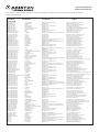
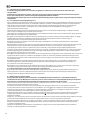
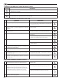
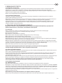
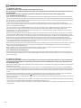
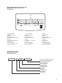
1. Торговая марка
2. Серийный номер
3. Модель
4. Материал бака
5. Максимальное давление
6. Объем
7. Номинальная мощность
8. Напряжение
9. Частота тока
10. Страна-изготовитель
11. Класс защиты
1. Торгова марка
2. Серійний номер
3. Модель
4. Матеріал бака
5. Максимальний тиск
6. Обсяг
7. Номінальна потужність
8. Напруга
9. Частота струму
10. Країна-виробник
11. Клас захисту
1. Brand
2. Serial Number
3. Model
4. Tank material
5. Maximum pressure
6. Volume
7. Rated power
8. Voltage
9. Current frequency
10. Country of origin
11. Protection rating
1
2
3 4
5 6
7 8
11
Hz
10
9
код продукта
код продукту
product code
код завода
код заводу
code of the plant
год производства
рік виробництва
year of production
день производства
день виробництва
day of production
уникальный порядковый номер
унікальний порядковий номер
unique sequential number
Идентификационная табличка
Iдентифiкацiйна табличка
Data plate
Серийный номер
Серiйний номер
Serial number
33
Page is loading ...
Page is loading ...

ООО «Аристон Термо Русь»
Россия, 127015, Москва,
ул. Большая Новодмитровская, 14, стр.1, офис 626
Тел. +7 (495) 213 03 00, 213 03 01
Горячая линия Аристон +7 (495) 777 33 00
e-mail: [email protected]
www.ariston.com/ru
ТОВ "АРІСТОН ТЕРМО УКРАЇНА"
Україна, 03680, Київ,
вул. Боженко, 86Е, корп.6
Тел. +380 44 496 25 18
е-mail: [email protected]
www.ariston.com/ua
Ariston Thermo SpA
Viale A. Merloni, 45
60044 Fabriano (AN)
Tel. 0732.6011
Telefax 0732.602331
Telex 560160
www.aristonthermo.it
420010536600 0613
-
 1
1
-
 2
2
-
 3
3
-
 4
4
-
 5
5
-
 6
6
-
 7
7
-
 8
8
-
 9
9
-
 10
10
-
 11
11
-
 12
12
-
 13
13
-
 14
14
-
 15
15
-
 16
16
-
 17
17
-
 18
18
-
 19
19
-
 20
20
-
 21
21
-
 22
22
-
 23
23
-
 24
24
-
 25
25
-
 26
26
-
 27
27
-
 28
28
-
 29
29
-
 30
30
-
 31
31
-
 32
32
-
 33
33
-
 34
34
-
 35
35
-
 36
36


Ariston ABS PLT R Series User manual
- Type
- User manual
- This manual is also suitable for
Ask a question and I''ll find the answer in the document
Finding information in a document is now easier with AI
in other languages
Other documents
-
LG V-K9851ND User manual
-
Atlantic Flat 30 User manual
-
 ARDESTO HD-Y120T Owner's manual
-
Atlantic Vertigo 075 L Acess S4 User manual
-
 ARDESTO HD-Y210 Owner's manual
-
 ARDESTO CHK-4001BR Owner's manual
-
ARDESTO SDK-200S Owner's manual
-
 ARDESTO CJK-1L Owner's manual
-
IK Multimedia iRig HD 2 User manual
-
Cooper & Hunter CH-S09FTXAM2S-SC Owner's manual


