Page is loading ...

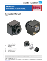
AM-1600GE
AB-1600GE
Digital Monochrome / Color
Progressive Scan GigE Vision Camera
Document Version: Ver.1.0
AMB-1600GE_ver.1.0_Apr09
User's Manual

AM-1600GE / AB-1600GE
1
Notice
The material contained in this manual consists of information that is proprietary to JAI Ltd.,
Japan and may only be used by the purchasers of the product. JAI Ltd., Japan makes no
warranty for the use of its product and assumes no responsibility for any errors which may
appear or for damages resulting from the use of the information contained herein. JAI Ltd.,
Japan reserves the right to make changes without notice.
Company and product names mentioned in this manual are trademarks or registered
trademarks of their respective owners.
Warranty
For information about the warranty, please contact your factory representative.
Certifications
CE compliance
As defined by the Directive 2004/108/EC of the European Parliament and of the Council, EMC
(Electromagnetic compatibility), JAI Ltd., Japan declares that AM-1600GE-P, AM-1600GE-
F,AB-1600GE-P and AB-1600GE-F comply with the following provisions applying to its
standards.
EN 61000-6-3 (Generic emission standard part 1 )
EN 61000-6-2 (Generic immunity standard part 1)
FCC
This equipment has been tested and found to comply with the limits for a Class B digital
device, pursuant to Part 15 of the FCC Rules. These limits are designed to provide reasonable
protection against harmful interference in a residential installation. This equipment
generates, uses and can radiate radio frequency energy and, if not installed and used in
accordance with the instructions, may cause harmful interference to radio communications.
However, there is no guarantee that interference will not occur in a particular installation. If
this equipment does cause harmful interference to radio or television reception, which can be
determined by turning the equipment off and on, the user is encouraged to try to correct the
interference by one or more of the following measures:
- Reorient or relocate the receiving antenna.
- Increase the separation between the equipment and receiver.
- Connect the equipment into a outlet on a circuit different from that to which the receiver
is connected.
- Consult the dealer or an experienced radio/TV technician for help.
Warning
Changes or modifications to this unit not expressly approved by the party
responsible for FCC compliance could void the user’s authority to operate the
equipment.

AM-1600GE-F / AM-1600GE-P
Supplement
The following statement is related to the regulation on “ Measures for the Administration
of the control of Pollution by Electronic Information Products “ , known as “ China RoHS “.
The table shows contained Hazardous Substances in this camera.
mark shows that the environment-friendly use period of contained Hazardous
Substances is 15 years.
嶷勣廣吭並㍻
嗤蕎嗤墾麗嵎賜圷殆兆各式根楚燕
功象嶄鯖繁酎慌才忽佚連恢匍何〆窮徨佚連恢瞳麟半陣崙砿尖一隈〇
云恢瞳ゞ 嗤蕎
嗤
墾麗嵎賜圷殆兆各式根楚燕 〃泌和
桟隠聞喘豚㍉
窮徨佚連恢瞳嶄根嗤議嗤蕎嗤墾麗嵎賜圷殆壓屎械聞喘議訳周和音氏窟伏翌
亶賜融延、窮徨佚連恢瞳喘薩聞喘乎窮徨佚連恢瞳音氏斤桟廠夛撹冢嶷麟半
賜斤児繁附、夏恢夛撹冢嶷鱒墾議豚㍉。
方忖仝15々葎豚㍉15定。

AB-1600GE-F / AB-1600GE-P
Supplement
The following statement is related to the regulation on “ Measures for the Administration
of the control of Pollution by Electronic Information Products “ , known as “ China RoHS “.
The table shows contained Hazardous Substances in this camera.
mark shows that the environment-friendly use period of contained Hazardous
Substances is 15 years.
嶷勣廣吭並㍻
嗤蕎嗤墾麗嵎賜圷殆兆各式根楚燕
功象嶄鯖繁酎慌才忽佚連恢匍何〆窮徨佚連恢瞳麟半陣崙砿尖一隈〇云恢瞳ゞ 嗤
蕎嗤墾麗嵎賜圷殆兆各式根楚燕 〃泌和
桟隠聞喘豚㍉
窮徨佚連恢瞳嶄根嗤議嗤蕎嗤墾麗嵎賜圷殆壓屎械聞喘議訳周和音氏窟伏翌
亶賜融延、窮徨佚連恢瞳喘薩聞喘乎窮徨佚連恢瞳音氏斤桟廠夛撹冢嶷麟半
賜斤児繁附、夏恢夛撹冢嶷鱒墾議豚㍉。
方忖仝15々葎豚㍉15定。

AM-1600GE / AB-1600GE
2
Table of Contents
1. General ................................................................................................ 4
2. Camera nomenclature .............................................................................. 4
3. Main Features ........................................................................................ 5
4. Locations and Functions ............................................................................ 6
5. Pin Assignment ....................................................................................... 7
5.1 12-pin Multi-connector (DC-in/GPIO/Iris Video) ....................................................... 7
5.2 Digital Output Connector for Gigabit Ethernet ........................................................ 7
5.3 D-sub 9 pin connector for GPIO (Auxiliary) ............................................................. 7
5.4 Internal DIP switch ......................................................................................... 8
6. GPIO (Inputs and outputs) .......................................................................... 9
6.1 Overview ..................................................................................................... 9
6.1.1 LUT (Cross Point Switch) ............................................................................. 10
6.1.2 12-bit Counter ......................................................................................... 10
6.1.3 Pulse Generators (0 to 1) ............................................................................. 10
6.2 Opto-isolated Inputs/Outputs ........................................................................... 10
6.2.1 Recommended External Input circuit diagram for customer ................................... 11
6.2.2 Recommended External Output circuit diagram for customer ................................. 11
6.2.3 Optical Interface Specifications ..................................................................... 11
6.3. Inputs and outputs table ................................................................................. 12
6.4. Configuring the GPIO module (register settings) ....................................................... 12
6.4.1 Input/Output Signal Selector ........................................................................ 12
6.4.2 12bit counter .......................................................................................... 14
6.4.3 Pulse generators (19 bit x 2) ........................................................................ 14
6.5. GPIO programming examples .............................................................................. 16
6.5.1 GPIO Plus PWC shutter ............................................................................... 16
6.5.2 Internal Trigger Generator .......................................................................... 17
7. GigE Vision Streaming Protocol (GVSP) ..........................................................18
7.1 Digital Video Output (Bit Allocation) ................................................................... 18
7.2 Bit Allocation (Pixel Format / Pixel Type) – AM-1600GE (monochrome) ......................... 18
7.2.1 GVSP_PIX_MONO8 (8bit) .............................................................................. 18
7.2.2 GVSP_PIX_MONO10 (10bit) .......................................................................... 18
7.2.3 GVSP_PIX_MONO10_PACKED ( 10 bit ) .............................................................. 19
7.2.4 GVSP_PIX_MONO12 ( 12 bit ) ......................................................................... 19
7.2.5 GVSP_PIX_MONO12_PACKED ( 12 bit ) .............................................................. 19
7.3 Bit Allocation (Pixel Format / Pixel Type) – AB-1600GE (Bayer mosaic color) .................. 19
7.3.1 GVSP_PIX_BAYGR8 “ Bayer GR8 “ ................................................................... 19
7.3.2 GVSP_PIX_BAYGR10 “Bayer GR10” .................................................................. 19
7.3.3 GVSP_PIX_BAYGR12 “ Bayer GR12” ................................................................ 20
8. Functions and Operations .........................................................................21
8.1 GigE Vision Standard Interface .......................................................................... 21
8.2 Recommended Network Configurations ............................................................... 21
8.2.1 Verified Network Interface Cards (NICs) ........................................................... 21
8.2.2 Video data rate (network bandwidth) .............................................................. 22
8.2.3 Disable Firewalls ....................................................................................... 24
8.2.4 Enabling Jumbo Frames .............................................................................. 24
8.2.5 Setting Receive Descriptors .......................................................................... 26
8.2.6 Interrupt Moderation rate ............................................................................ 27
8.2.7 Calculating and setting Inter-Packet Delay........................................................ 27
8.2.8 Confirm the Filter Driver is used .................................................................... 27
8.2.9 Others ................................................................................................... 28
8.3 Basic functions ............................................................................................. 29
8.3.1 Vertical binning functions (AM-1600GE only) ..................................................... 29
8.3.2 Starting pixel – Bayer color mosaic ................................................................. 30
8.3.3 Partial Scanning ....................................................................................... 30

AM-1600GE / AB-1600GE
3
8.3.4 Electronic Shutter ..................................................................................... 31
8.3.1 Rear panel indicator .................................................................................. 32
8.3.2 Test signal generator ................................................................................. 32
8.4 Pre-processing functions (overview) ................................................................... 32
8.4.1 Blemish compensation (Register 0xA128) (AM-1600GE only) ................................... 32
8.4.2 Shading Compensation (Pixel uniformity) (Register xA11C)(AM-1600GE only) .............. 33
8.4.3 Programmable Look Up Table (LUT) ................................................................ 33
8.4.4 Auto L/R channel balance (Registers 0xA0B8, 0xA0BC) ........................................ 34
8.5. Other functions .............................................................................................. 34
8.5.1 Bayer White Balance (Register 0xA0D0) (AB-1600GE only) ..................................... 34
8.5.2 Automatic Gain Control(Registers, 0xA0B0 AGC select/0xA0B4 AGC reference) ........... 34
8.6. Sensor layout and timing ................................................................................... 35
8.6.1 CCD Sensor Layout ................................................................................... 35
8.6.2 Horizontal timing (Normal continuous mode) .................................................... 36
8.6.3 Vertical timing (Normal continuous mode) ....................................................... 36
8.6.4 Partial Scanning ....................................................................................... 37
8.6.5 Vertical binning (AM-1600GE only) ................................................................. 38
8.5 Operation Modes........................................................................................... 40
8.5.1 Continuous operation ................................................................................. 40
8.5.2 Edge Pre-select Trigger Mode (EPS) ................................................................ 41
8.5.3 Pulse Width Control Trigger Mode (PWC) .......................................................... 42
8.5.4 Sequence Trigger Mode (EPS) ........................................................................ 43
8.5.5 Delayed Readout Mode (EPS, PWC) ................................................................. 44
8.5.6 Optical Black transfer Mode ......................................................................... 45
8.5.7 Multi ROI mode (Multi Region of Interest) ......................................................... 45
8.6 Operation Mode and Functions matrix ................................................................. 46
9. Register Map .........................................................................................47
10. External Appearance and Dimensions ...........................................................58
11. Specifications .......................................................................................60
11.1 Spectral response ......................................................................................... 60
11.2 Specification table ........................................................................................ 61
12. Appendix .............................................................................................63
12.1. Precautions ................................................................................................. 63
12.2. Typical Sensor Characteristics ........................................................................... 63
12.3. Caution when mounting a lens on the camera ........................................................ 63
12.4. Exportation ................................................................................................. 64
12.5. References .................................................................................................. 64
Changes history ............................................................................................... 1
User's Record .................................................................................................. 2

AM-1600GE / AB-1600GE
4
1. General
The AM-1600GE and AB-1600GE are 16-megapixel, high resolution GigE Vision Compliant
cameras for applications such as high density board inspection, flat panel display
inspection, and so on. The AM-1600GE is a monochrome progressive scan CCD camera and
the AB-1600GE is the equivalent Bayer mosaic progressive scan CCD camera. Both cameras
have a 43.3mm diagonal CCD with 16 million pixels resolution and a continuous frame rate of
3.0 frames per second. The AM-1600GE and AB-1600GE support partial scan read out for faster
frame rates. The AM-1600GE also has a vertical binning mode for a faster frame rate, as well
as higher sensitivity.
The AM-1600GE has internal pre-processing circuits for blemish compensation, shading
compensation and a LUT(Look Up Table). Both cameras accept external trigger pulses with
EPS ,PWC, Sequential and Frame Delay modes available.
The Gigabit Ethernet digital output is selectable 8 bits,10 bits or 12 bits. Lens mount options
include F mount or Universal P mount, which is the factory option.
The AM-1600GE and AB-1600GE also comply with the GenICam standard and contain an
internal XML file that is used to describe the functions/features of the camera. For further
information about the GigE Vision Standard, please go to www.machinevisiononline.org
and
about GenICam, please go to www.genicam.org
.
As an application programming interface, JAI provides a SDK (Software Development Kit). This
SDK includes GigE Vision Filter Driver, JAI Control tool, software documentation and code
examples.
The JAI SDK can be downloaded from www.jai.com
.
The latest version of this manual can be downloaded from www.jai.com
For camera revision history, please contact your local JAI distributor.
2. Camera nomenclature
The standard camera composition consists of the camera main body and C-mount protection
cap.
The camera is available in the following versions:
AM-1600GE-P, AM-1600GE-F
Where A
stands for "Advanced" family, M stands for "Monochrome", 1600 represents the
resolution "16 million pixel" and GE
stands for "GigE Vision" interface. P for the Universal P
mount version and F
for the Nikon F mount version.
AB-1600GE-P, AB-1600GE-F
Where A
stands for "Advanced" family, B stands for "Bayer mosaic color", 1600 represents the
resolution "16 million pixel" and GE
stands for "GigE Vision" interface. P for the Universal P
mount version and F
for the Nikon F mount version.

AM-1600GE / AB-1600GE
5
3. Main Features
• C3 Advanced series progressive scan camera
• GigE vision, GenICam compliant
• Monochrome and Bayer mosaic color versions
• KAI-16000 IT CCD, 43.3mm diagonal (35mm film size)
• 4872 (h) x 3248 (v) active pixels
• 7.4 µm square pixels
• 12- or 10- or 8-bit output
• 16 bits signal processing
• 3 frames/second with full resolution in continuous and triggered operation
• Variable partial scan is available with user-definable height and starting point
• 2X vertical binning mode (AM-1600GE only)
• Programmable shutter from 3 lines(296μs) to 3327 lines (328 ms)
• Edge Pre-select and Pulse Width Control trigger modes
• Sequence trigger mode for on-the –fly change of gain, exposure and ROI
• Built in programmable Look Up Table (LUT) for gamma, 0.45
• Blemish compensation circuit built in(AM-1600GE only)
• Shading compensation(pixel non-uniformity compensation)(AM-1600GE only)
• L/R channel balance
• AGC(Automatic Gain Control) circuit provided
• Built-in test pattern generator
• Exposure time from 1 line(98.66μs) to 2 sec.* using Pulse Width trigger mode
• GPIO in combination with Pulse Width trigger for more precise exposure time
• One-push and manual Bayer white balance (AB-1600GE only)
• Programmable GPIO with opto-isolated inputs and outputs
• Two types of lens mounts available as factory option, Universal P mount or Nikon F
mount
• Comprehensive software tools and SDK for Windows XP/Vista (32 bit”x86” and 64
bit “x64” JAI SDK Ver. 1.2.1 and after )
*For best image quality, the maximum recommended exposure time is <6 frames (2
seconds), however, depending on your application, significantly longer exposure may
still produce an acceptable signal-to-noise ratio, even without applying any external
cooling.

AM-1600GE / AB-1600GE
6
4. Locations and Functions
1 Lens mount Universal P mount (Note *1)
1 Lens Mount Nikon F mount (Note*2)
2 CCD sensor 43.3mm diagonal CCD sensor
3 Lock knob Lens lock knob for Nikon F mount lens
4 12-pin connector DC +12V and GPIO interface
5 D-sub 9 pin connector Auxiliary GPIO interface (LVDS IN and TTL IN/OUT)
6 RJ-45 GigE Vision I/F. Accepts connector w thumbscrews.
7 LED Indication for Power and trigger inputs
8 LED Indication for GigE Network condition: LINK
9 LED Indication for GigE Network condition: ACT
Holes for RJ-45 thumbscrews Horizontal type (above and below RJ-45)(Note*3)
○
11
Holes for RJ-45 thumbscrews Vertical type (left and right of RJ-45) (Note *3)
○
12
Mounting holes M3 depth 5 mm for tripod mount plate (Note *4)
*1) Note: Rear protrusion on P-mount lens must be less than 11.0mm.
*2) Note: Rear protrusion on F-mount lens must be less than 12.0mm.
*3) Note: When an RJ-45 cable with thumbscrews is connected to the camera, please do not
excessively tighten screws by using a screw driver. The RJ-45 receptacle on the
camera might be damaged. For security, the strength to tighten screws is less
than 0.147 Newton meter (Nm). Tightening by hand is sufficient in order to
achieve this. When D-SUB 9 pin connector is used, use the vertical type.
*4) Note: The tripod adapter plate MP-41 can be used with AM/AB-1600GE
Fig.1 Locations
LINK ACT
.
DC IN/TRIG
GP IO
POW ER/ TR IG
GigE
①
②
③
④
⑤⑥
⑦
⑧
⑨
⑩
⑪
⑫
⑫
AM-1600GE-F/AB-1600GE-F Front
AM-1600GE-P/AB-1600GE-P Front

AM-1600GE / AB-1600GE
7
5. Pin Assignment
5.1 12-pin Multi-connector (DC-in/GPIO/Iris Video)
Type: HR10A-10R-12PB
(Hirose) male.
(Seen from the rear of
camera)
Fig. 2 12-pin connector.
5.2 Digital Output Connector for Gigabit Ethernet
Type: RJ-45 : HFJ11-1G02E-L21RL or equivalent
The digital output signals follow
the Gigabit Ethernet interface
using an RJ-45 conforming
connector. To the right is a
table with the pin assignment
for Gigabit Ethernet connector.
Fig. 3 Gigabit Ethernet
connector
5.3 D-sub 9 pin connector for GPIO (Auxiliary)
Type: DD-09SSG
Fig. 4 D-sub 9 pin connector
*1: can be changed by DIP SW(SW600).
Pin no.
Signal
Remarks
1 GND
2 +12 V DC input
3 Opt IN 2 (-) / GND (*1)
GPIO IN / OUT
4 Opt IN 2 (+)/Iris Video out (*1)
5 Opt IN
1 ( -
)
6 Opt IN 1 ( + )
7 Opt Out 1 ( -
)
8 Opt Out 1 ( + )
9 Opt Out 2 ( -
)
10 Opt Out 2 ( + )
11 + 12 V DC input
12 GND
*1: Iris Video output function can be set by the internal DIP
switch (SW601).
Pin No
In/Out Name
1
In/Out MX1+ (DA+)
2
In/Out MX1-
(DA-)
3
In/Out MX2+ (DB+)
4
In/Out MX3+ (DC+)
5
In/Out MX3-
(DC-)
6
In/Out MX2-
(DB-)
7
In/Out MX4+ (DD+)
8
In/Out MX4-
(DD-)
No
I/O
Name
Note
1
I
LVDS In1-
2
I
LVDS In1+
3
I
TTL IN 1
75ohm Terminator *1
4
O
TTL Out 1
5
GND
6
NC
7
NC
8
O
TTL Out 2
9
GND
3
4
5
6
7
8
9
10
11
12
1
2
15
69
123
456
7
8

AM-1600GE / AB-1600GE
8
5.4 Internal DIP switch
In order to change, the top cover must be removed.
Fig.5 DIP switches
SW600 For selection of TTL IN 1 75
ohm ON or OFF
Factory default is UP position ( 75 ohm
OFF). To set 75 ohm ON, these two
switches must be DOWN.
Right side, as seen from the
lens side

AM-1600GE / AB-1600GE
9
6. GPIO (Inputs and outputs)
6.1 Overview
All input and output signals pass through the GPIO (General Purpose Input and Output) module.
The GPIO module consists of a Look-Up Table (LUT – Cross-Point Switch), 2 Pulse Generators
and a 12-bit counter. In the LUT, the relationship between inputs, counters and outputs is
governed by internal register set-up.
Fig.6 GPIO interface
Some of the descriptions in this diagram differ from those displayed in the camera control
tool. The following table shows display names and descriptions.
Line Source Line Selector
Description Display Name
Description
Display Name
OPT IN 1 Line5-Optical In1
TTL OUT 1
Line1-TTL Out1
OPT IN 2 Line6-Optical In2
TTL OUT 2
Line2-TTL Out2
TTL IN 1 Line7-TTL In
OPT OUT 1
Line3-Optical Out1
LVDS IN 1 Line8-LVDS In
OPT OUT 2
Line4-Optical Out1
The blocks shown in the above diagram have the following functionality:

AM-1600GE / AB-1600GE
10
6.1.1 LUT (Cross Point Switch)
The LUT works as a cross-point switch which allows connecting inputs and outputs freely. The
signals LVAL_IN, FVAL_IN and EEN_IN all originate from the camera timing circuit.
On this diagram, “Trigger 0” is used for camera exposure and “Trigger 1” is used for Delayed
Readout. The “Time Stamp Reset” signal can reset the time stamp specified in GigE Vision
Format. This signal can be used when time stamps from several cameras connected are
coincident with each other. The “Sequence reset” resets the sequential settings. Outputs
from LUT described on the right side show GPIO settings for LINE SELECTOR in the JAI Camera
Control tool and inputs to LUT on the left side show GPIO settings for LINE SOURCE in the JAI
Camera Control tool. Refer to Chapter 6.3
.
6.1.2 12-bit Counter
A camera pixel clock can be used as a source. The counter has a “Divide by N”, where N has
the range 1 through 4096, allowing a wide range of clock frequencies to be programmed.
Setting value 0 is bypass, setting value 1 is 1/2 dividing, and setting value 4095 is 1/4096
dividing. As the pixel clocks for the AM-1600GE and AB-1600GE are 30 MHz, the output
frequency is varied from 30MHz to 10.135 KHz.
6.1.3 Pulse Generators (0 to 1)
Each pulse generator consists of a 19-bit counter. The behavior of these signals is defined by
their pulse width, start point and end point.
The pulse generator signals can be set in either triggered or periodic mode.
In triggered mode, the pulse is triggered by the rising edge, falling edge, high level or low
level of the input signal. In periodic mode, the trigger continuously generates a signal that is
based on the configured pulse width, starting point and end point.
Each pulse generator operates at the frequency created in the 12-bit counter. As the pixel
clock (30 MHz) is used as the main frequency, the frequency of pulse generator is 30MHz to
10.135 KHz.
6.2 Opto-isolated Inputs/Outputs
The control interface of the C3 GigE Vision camera series has opto-isolated inputs and outputs,
providing galvanic separation between the camera's inputs/outputs and peripheral equipment.
In addition to galvanic separation, the opto-isolated inputs and outputs can cope with a wide
range of voltages; the voltage range for inputs is +3.3V to +24V DC whereas outputs will
handle +5V to +24V DC.
Fig.7 Photo coupler

AM-1600GE / AB-1600GE
11
6.2.1 Recommended External Input circuit diagram for customer
Fig.8 External Input Circuit、OPT IN 1 and 2
6.2.2 Recommended External Output circuit diagram for customer
Fig.9 External Output Circuit, OPT OUT 1 and 2
6.2.3 Optical Interface Specifications
The relation of the input signal and the output signal through optical interface is as follows.
+3.3V to +24V
User Power
1
2 3
4
5
PS8101
2 3
2SC4098
2k2
1 3
2
02CZ2.0Z
120
10kB
3k3
hirose-12 connector
hirose-12 connector
User
side
JAI
C3_Series CAMER A
side
EXTERNAL INPUT
+3.3V
IN
hirose-12 connector
Pin 8 and 10
hirose-12 connector
Pin 7 and 9
OUT
270
+5V to +24V
User Power
2
User
side
Camera
Inside
From Camera Circuit
EXTERNAL OUTPUT
+12V
220
To

AM-1600GE / AB-1600GE
12
Conditions for Input
Input Line Voltage Range
+3.3V ~ +24V
Input Current
6mA ~ 30mA
Minimum Input Pulse Width to Turn
ON
0.5μs
Output Specifications
Output Load(Maximum Current)
100mA
Minimum Output Pulse Width
20μs
Time Delay Rise TDR
0.5μs ~ 0.7μs
Rise Time RT
1.2μs ~ 3.0μs
Time Delay Fall TDF
1.5μs ~ 3.0μs
Fall Time FT
4.0μs ~ 7.0μs
Fig.10 Optical Interface Performance
6.3. Inputs and outputs table
Output Ports
Trigger
0
Trigger
1
OPT
OUT1
OPT
OUT2
TTL
OUT1
TTL
OUT2
Time
Stamp
Reset
Seque
nce
Reset
Pulse
Gener
ator 0
Pulse
Gener
ator 1
Input Ports
LVAL IN × × × × ○ ○ × × ○ ○
FVAL IN × × × × ○ ○ × × ○ ○
EEN IN × × ○ ○ ○ ○ × × ○ ○
OPT IN 1 ○ ○ ○ ○ ○ ○ ○ ○ ○ ○
OPT IN 2 ○ ○ ○ ○ ○ ○ ○ ○ ○ ○
TTL IN ○ ○ ○ ○ ○ ○ ○ ○ ○ ○
LVDS IN ○ ○ ○ ○ ○ ○ ○ ○ ○ ○
Soft
Trigger 0
○ ○
○ ○ ○ ○ ○ ○ ○ ○
Soft
Trigger 1
○ ○
○ ○ ○ ○ ○ ○ ○ ○
Soft
Trigger 2
○ ○
○ ○ ○ ○ ○ ○ ○ ○
Soft
Trigger 3
○ ○
○ ○ ○ ○ ○ ○ ○ ○
Pulse
Gen. 0
○ ○
○ ○ ○ ○ ○ ○ × ○
Pulse
Gen. 1
○ ○
○ ○ ○ ○ ○ ○ ○ ×
LEGEND: 0 = valid combination / x = Not valid (do not use this combination)
The shaded parts are for the interface to external equipment.
6.4. Configuring the GPIO module (register settings)
6.4.1 Input/Output Signal Selector
Address
Internal Name GenICam Name
Access
Size
Value (Range)
0xB060
Selector CAMERA TRIGGER
0 ( for Camera Trigger )
Camera Trigger
0
R/W 4
GPIO Selector:
Line Source ( SDK)
0x00:CAMERA LVAL IN
0x02:CAMERA FVAL IN
0x03:CAMERA EEN IN
0x04:OPT 1 IN
0x05:OPT 2 IN
0xB064
Selector CAMERA Trigger 1
( For Delayed Trigger )
Camera Trigger
1
R/W 4
0xB070 Selector GPIO PORT 1 GPIO_Port1 R/W 4

AM-1600GE / AB-1600GE
13
0xB074 Selector GPIO PORT 2 GPIO_Port2 R/W 4
0x06:TTL 1 IN
0x07:LVDS 1 IN
0x0C:USER OUT 0
0x0D:USER OUT 1
0x0E:USER OUT 2
0x0F:USER OUT 3
0x10:Pulse Generator 0
0x11: Pulse Generator 1
0x7F: No connect
Line selector (SDK)
0x00:CAMERA Trigger 0
0x01:CAMERA Trigger 1
0x04:TTL OUT 1
0x05:TTL OUT 2
0x06:OPT OUT 1
0x07:OPUOUT 2
0x0C:Pulse Generator 0
0x0D:Pulse Generator 1
0x10:Time stamp reset
0x11:Sequence table reset
0x7F: No connect
Add 0x80 will result in low
active output.
0xB090
Pulse Generator 0
Selector
PulseGenerator
0
R/W 4
0xB094
Pulse Generator 1
Selector
PulseGenerato
r
1
R/W 4
0xB0A0
Selector Time Stamp
Reset
TimeStamp
Reset
R/W 4
0xB0A4
Selector Sequence Table
Reset
Sequence Table
reset
R/W 4
The following shows the JAI SDK Camera Control Tool for setting GPIO registers.
Line Selector
Line Source
Line Polarity

AM-1600GE / AB-1600GE
14
Start Point
End Point
Length
Start Point
End Point
Length
6.4.2 12bit counter
Address
Internal Name GenICam Name
Access
Size
Value (Range)
0xB000 Counter Clock Choice ClockSource
R/W
4
0x01: Pixel Clock
0xB004 Counter Dividing Value ClockPreScaler
R/W 4
0x000: Bypass
0x001: 1/2 Dividing
0x002: 1/3 Dividing
|
0xFFF: 1/4096 Dividing
6.4.3
Pulse generators (19 bit x 2)
There are 2 pulse generators (designated 0 through 1) that can be used to create various
timing scenarios by programming start point, endpoint, length and repeats.
The following drawing is an example of settings.
FVAL is used for the input of Pulse Generator 0 and the clock after the rising edge of FVAL
counts 100 clocks for the high period of the pulse and 102 clocks for the pulse length.
As 2400 is for Clock Pre-scaler, the output of 12 bit counter is 25 KHz, which is 40µs.
Pulse Generator 0 creates a 4 ms pulse.
Fig.11 Example of Pulse Generator setting
The following shows JAI SDK Camera Control Tool for setting Pulse Generator.

AM-1600GE / AB-1600GE
15
Address
Internal Name GenICam name
Access
Size
Value (range)
0xB008 Length Counter 0
Pulse Generato
r
Length
R/W 4 0x00001 to 0xFFFFF
0xB00C Start point Counter 0(1)
PulseGenerato
r
StartPoint
R/W 4 0x00000 to 0xFFFFF
0xB010 Start point Counter 0(2)
PulseGenerator
RepeatCOunt
R/W 4
0x00: infinite
0x01: 1 time
|
0xFF: 255 times
0xB014 End point Counter 0
PulseGenerato
r
EndPoint
R/W 4 0x00001 to 0xFFFFF
0xB018 Counter Clear 0
PulseGenerator
Clear
R/W 4
0x00: Free Run
0x01: High Level Clear
0x02: Low Level Clear
0x04: Rising Edge Clear
0x08: Falling Edge
Clear
0xB01C Length Counter 1
Pulse Generato
r
Length
R/W 4 0x00001 to 0xFFFFF
0xB020 Start point Counter 1(1)
PulseGenerato
r
StartPoint
R/W 4 0x00000 to 0xFFFFF
0xB024 Start point Counter 1(2)
PulseGenerator
RepeatCount
R/W 4
0: Infinite
1: 1 time
|
255: 255 times
0xB028 End point Counter 1
PulseGenerato
r
EndPoint
R/W 4 0x00001 to 0xFFFFF
0xB02C Counter 1 Clear
PulseGenerator
Clear
R/W 4
0x00: Free Run
0x01: High Level Clear
0x02: Low Level Clear
0x04: Rising Edge Clear
0x08: Falling Edge
Clear

AM-1600GE / AB-1600GE
16
6.5. GPIO programming examples
6.5.1 GPIO Plus PWC shutter
Example: 10µs unit pulse width exposure control (PWC).
Pixel clock is 30MHz. 300 clocks (400-100) equal 10µs.
Address
R
egister
Value
0xA040 Trigger Mode
2
= PWC (Pulse Width Control)
c
0xB090 Pulse Generator 0 Selecto
r
4 =OPT IN
1
d
0xB000 Clock Choice
1 =
Pixel Cloc
k
( 60MHz )
0xB004 Counter Dividing Value
0 = Pass through
0xB008 Length Counter 0
1000 Clocks
0xB00C Start point Counter 0(1)
100 Clocks
0xB010 Start point Counter 0(2)
1
0xB014 End point Counter 0
400
Clocks
0xB018 Counter Clear 0
4 = Rising Edge Clear
e
0xB060 CAMERA TRIGGER
Selector
16
= pulse generator 0
c
0xB090 Pulse Generator 0 Selecto
r
4 =OPT IN
1
Fig.12 Pulse Generator Timing Example 1
OPT IN 1
100
400
1000
P
ulse Generator 0
100
1000
o
utput

AM-1600GE / AB-1600GE
17
6.5.2 Internal Trigger Generator
Example: Create a trigger signal and trigger the camera
Fig.13 Pulse Generator 0 timing Example 2
Address Registe
r
Value
0xA040 Trigger Mode
1 = EPS
c
0xB000 Clock Choice
1 = Pixel Cloc
k
0xB004 Counter Dividing Value
2959
= 1/2960 dev(Line
Rate)
0xB008 Length Counter 0
1000 Clocks
0xB00C Start point Counter 0
(1)
100 Clocks
0xB010 Start point Counter 0
(2)
0 = Infinite
0xB014 End point Counter 0
500 Clocks
0xB018 Counter Clear 0
0 = Free Run
d
0xB060 CAMERA TRIGGER
Selector
16
= pulse generator 0
Pulse Generator 0
100 Line
500 Line
1000 Line
output
Pulse Generator 0
100 Line
500 Line
1000 Line
output
/