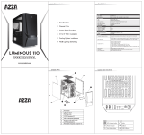
SIRIUS
CSAZ-206/206S
www.azzatek.com

Specifications
SIRIUS
CSAZ-206, CSAZ-206S
ATX Mid-Tower
Black (exterior)/Black (interior)
SECC Steel
Yes
No
ATX, Micro ATX
3
3x 2.5" SSD drive bay
3
7
1xUSB 3.0(CSAZ-206), 2xUSB 2.0, Audio
2xUSB 2.0(CSAZ-206S), Audio
1x120mm Blue LED front fan,
1x120mm black rear fan(CSAZ-206)
17" x 7.9" x 17.5" (430mm x 200mm x 445mm)
1xUSB 3.0(CSAZ-206)
2x 120mm fans (optional) located on top, to exhaust hot air
1x 120mm blue LED fans in the front to cool the HDD
and VGA card.
1x 120mm(CSAZ-206) fan located in the rear, to exhaust hot air
supports up to 2x120mm watercooling radiator
Power Supply located at the bottom, two ways to install
Power supply which provide more ecient airow
Cables are hidden behind the pre-drilled motherboard tray;
better cable management means better air ow
A pre-cut hole for easy installation of CPU cooler,
eliminating the need to remove the motherboard
Model
Model Name:
Model Number:
Specs
Type:
Color:
Material:
Side Panel Window:
With Power Supply:
Motherboard Compatibility:
Expansion
External 5.25" Drive Bays:
Internal 2.5" Drive Bays
Internal 3.5" Drive Bays:
Expansion slots:
Front Ports
Cooling System
120mm Fan:
Physical Specs
Dimensions(HxWxD)
Features
USB 3.0 ready
Ultimate Cooling System:
Supports a Total up to 4 Fans
Supports Water Cooling:
Bottom Mount Power Supply:
Cable Management:
Easy installation of CPU Cooler

Parts List
10
4
7
6
5
11
12
1
2
9
8
3
Case
Left Side Panel
Right Side Panel
Front Penel
Door
Front Bezel
5.25’’Metal Mesh
3.5” Metal Mesh
2.5” Metal Mesh
Foot Pad
Front:Blue LED Fan
Bottom:Black Fa
1
2
3
4
5
6
7
8
9
10
11
12

Aircooling system

200mm450 mm
430 mm
POWER
RESET
POWER
RESET
USB 2.0 (Black)
USB 3.0 (Blue)
Mic
Audio
Diagram
Assembly kit
Figure Parts Name Quantity
Motherboard Support
6*6 Hex washer screw
Speaker
2
1
8
20
4
12
PCI Cover
M3*5 washer screw
Fan Screw

Installation Instruction
1.Opening the case
3.Power supply installation
4.5.25” floppy device installation
2.Front panel disassembly
1.1 Remove the thumbscrews from the side panel
1.2 Slide the side panel toward the rear to open the case
3.1 Place the power supply into its proper location
3.2 Tighten the screws
4.1 Remove the mesh cover on the front panel covering the drive bay by pressing
4.2 One (either left of right) of the two tabs inward to unlock, as in the direction shown in the figure
4.3 Slide the device into the drive bay
2.1 Put your hand on the bottom of the front panel than pull it out

7.1 Closed the side panel along with those screws that we’ve remove from
6.1 Place the SSD in HDD cage then fasten with thumbscrews
6.2 Shown fan the picture
6.2.5”SDD Device installation
7.Close the case
5.HDD Device installation
5.1 Remove the mesh cover on the front panel covering the drive bay by pressing
5.2 One (either left of right) of the two tabs inward to unlock, as in the direction shown in the figure
5.3 Slide the device into the drive bay

Front Connector Installation Guide
Please refer to your motherboard user manual on the sections of “USB connector”And “audio connector”.
Please verify the pin definition before connecting the connectors to the motherboard
Remark:
1. USB and Audio connectors have foolproof design, can only be inserted in one direction
2. LED connectors have electrically positive and negative poles
/


