
** Available only in model AV-1500-MINI
AV-300-MINI/1500-MINI is radio transmission system designed to transmit analog Video (composite
CVBS) and audio signals outside of buildings. The device uses one of seven available radio channels
(5470MHz ~ 5860MHz), set by dipswitches. Digital PLL generates high frequency, providing excellent work
stability and high resistance to radio interference from adjacent frequencies.
Device includes an airtight case with active directional antenna and required connectors. This solution
allows to obtain optimal radio range because radio signal isn’t attenuated on cables beetween antenna and
radio transmitter / receiver.
System can be used on professional CCTV installations to transmit Audio and Video from cameras, to
Video presentation, Audio/Video solutions in home and hobby.
Audio Video signal are transmit in real-time without compression and delays. It’s important to choose
right place for installation and precisely align antennas.
Place of installation
5.8GHz frequency provides high quality Video and protection from radio interferences, but it has defects just
like devices using microwave frequencies (for example satellite antenna).
1. Antennas in devices needs to be accurately aligned relative to each other.
2. All solids, also the wood and leaves of trees attenuates microwaves.
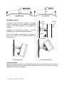
3. Antennas of sets need to be visible and the field of view needs to be clean at 3 meters from center of
antenna (6m diameter).
Sometimes is important to use high mast, trim trees or remove other barriers. Devices are more safety
against radio signal attenuation, when are hanging higher off the ground.
Land view from top. Land diameter without hindrance should be at least 6m.
5.8GHz Audio / Video signal transmission set
Model
AV-1500-MINI
v1.1
AV-300-MINI

** Available only in model AV-1500-MINI
Mounting of device*
Construction of AV-1500-MINI is designed to mounting
on wall of buildings. Device is equipped on articulated
bracket, which allows regulation in horizontally and
vertically.
Regulation in horizontally and vertically is done by
loosening screw, which clamping the articulated.
There is also possible independently the regulation in
level after loosening bolts connecting bracket with
mounting base.
Vertical adjustment Horizontal adjustment
Connecting cables
Disconnect power supply before connecting cables protect device from accidental short circuits and
dam-age. Connecting can be executed before mounting device on mast or when it's mounted
(Depending on technical possibilities).
Wire Gland
A
ntenna
Bracket
Base
Wall

** Available only in model AV-1500-MINI
V
IDEO INPUT
123
ON
4
V
IDEO OUTPUT
123
ON
4
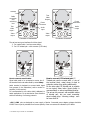
Connector of transmitter Connector of receiver
The set has two types interfaces for Video signal:
1. For coaxial cable - low-loss screw clamps
2.
For UTP twisted pair – with converter (UTP balun)
How to connect coaxial cable.
Signal cable need to be connected to center pin of
the terminal block and cable shield by metal clamp.
Audio terminal is designed to connect Audio signal
from camera (in the transmitter) and to monitor or
amplifier (in the receiver).
It’s recommended to use cable shield, dedicated to
Audio applications. It's protect device from distortion
and hum collecting from energy network.
+12V / GND pins are designed to power supply of device. Connected power adapter voltage should be
12VDC. Power input is protected from reverse polarity. Power correctness is indicated by LED diode.
How to connect UTP twisted pair.**
Twisted pair need to connect with +/- pins o
f
the terminal block, metal clamp is used to
protection cables from pulling additionally.
On the other side UTP twisted pair is possible
to use typical Video balun (good quality is
recommended) or active transmitter/receiver.
T
he set can be powered with available cables
of twisted pair, but you need remembe
r
about voltage drop. Incoming volta
g
e can’
t
be lower that 9V
A
ntenna
Cable
connection
and
switching
test
Test
Video
Input**
Video
output
Power
connector
Audio
input
Test
Video
Output**
Video
output
Power
connector
Audio
output
V
IDEO OUTPUT
123
ON
4
V
IDEO OUTPUT
123
ON
4

** Available only in model AV-1500-MINI
Test Video input in transmitter, is designed to temporarily connect source of Video. Do not connect at
the same time a signal from 2 sources - for example of two cameras! **
Test Video output in receiver, is designed to test monitor at the time of making device regulation – may
be simultaneously connect main receiver and test monitor.**
Must be pay attention to respectively sealing of transmitter and receiver. Factory mounted is
only one gland. Second can by mounted only where to power supply and Video signal are use
suitable cables. Glands must by twisted tight, to prevent from ingress of moisture into device.
Screwing front cover, need to check for the correct placement of gaskets and tighten fixing
screws. Where water getting to inside is a result of bad seal of housing and may be reason of
damage the device and loss of warranty.
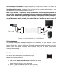
Example of typical application for AV-1500-MINI model
Device adjustment
The set doesn’t need special knowledge and expensive tools for installing. The most important is proper
positioning of transmitter and receiver a according to recommendations of instructions and aligned relative
antennas to each other. System in MINI version hasn’t radio measurement function and installer can verify
antennas setting only optically. When the antenna isn't set exactly and the weather conditions are
unfavourable (snowstorm, fog, heavy rain) may appear deterioration of image quality and will be necessary
correcting antenna settings.
The PRO version has radio function of measurement system.
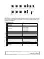
You must set radio channel before you connect power supply.
Rotary switch on the transmitter and receiver is used to this.
Adhere to the following instructions:
1. Radio channel must to be set the same in transmitter and receiver.
2. When we are dealing with sets work in immediate vicinity or in close proximity to transmitter and
receiver, channels must be set every second one.
3. Number of radio channel are the same like number on switch.
4. Turning off all switches is equivalent to selecting channel 1.
Video + Audio
Audio
Video
123
ON
4

** Available only in model AV-1500-MINI
123
ON
OFF
ON
Kanał 1 Kanał 1Kanał 2Kanał 3
Kanał 7Kanał 6Kanał 5Kanał 4
4 123
ON
4 123
ON
4 123
ON
4
123
ON
4 123
ON
4 123
ON
4 123
ON
4
123
ON
4 123
ON
4
Tryb
normalny
Test
Only DIP 1~3 are used to set radio channels.
TESTU
MODE**
– it’s designed to connected additional camera or / and service monitor, in order to verify proper
operation of system. In normal mode the test clamp is connected electronically in main input (transmitter) and output
(receiver ). When test mode is enabled by using switch no. 4, only test clamp is connected to transmitter / receiver,
main input / output is disconnected.
Technical specification:
No
Parameter
Value
1 Video channels
Coaxial cable: 1 x 75Ω
UTP twisted pair: 1 x 100 Ω**
2 Audio channels
1 x 2Vp-p
3 Radio channels
Channel 1: 5470MHz
Channel 2: 5760MHz
Channel 3: 5780MHz
Channel 4: 5800MHz
Channel 5: 5820MHz
Channel 6: 5840MHz
Channel 7: 5860MHz
4 Antenna
Directional, active (AV-1500) / passive (AV-300)
5 Receiver sensitivity
-80dB
6 Transmitter power
25mW, 14dBm
7 Deviations for Video channel (at 10kHz)
4MHz
8 Frequency control
PLL
9 Work temperature
-20°C ~ 40°C
10 Hermetic class
IP65
11 A/V Modulation
FM
12 Frequency Range for Video
50Hz ~ 5,5MHz
13 Frequency Range for Audio
50Hz~20kHz
14 Power supply
9~13,5VDC
15
Power consumption
Transmitter: 300mA @ 12VDC
Receiver: 120mA @ 12VDC
16 Max diameter of mast
40mm
17 Surge protection
600W for power supply, Video and Audio
18 Radio range
AV-300: Up to 300 meters in open area
AV-1500: Up to 1500 meters in open area
Manufacturer reserves right to change technical specification without to prior notification.
Producer of wireless Audio / Video transmission
www.AV-LiNK.pl
Channel 1 Channel 1 Channel 2 Channel 3
Channel 4 Channel 5 Channel 6 Channel 7
Normal
mode
-
 1
1
-
 2
2
-
 3
3
-
 4
4
-
 5
5


AV Link AV-1500-MINI User manual
- Type
- User manual
- This manual is also suitable for
Ask a question and I''ll find the answer in the document
Finding information in a document is now easier with AI
Other documents
-
PRESIDENT HARRY III Owner's manual
-
Tranwo Technology Corp O6LTTA-AB5805T User manual
-
RF-Link AVS-5812 Installation guide
-
dji Phantom 2 User manual
-
 ASE VS58D4 User manual
-
Artsound TXS-882HT Datasheet
-
 MuxLab CATV Balun II User guide
-
 Calrad Electronics 40-998-HS Datasheet
-
Spektrum Focal V2 FPV Wireless Headset User manual
-
 Extron electronics IN1128 User manual


