Page is loading ...

Quick Start Guide
NXA-RGB Modero RGB/VGA Interface Card
For more detailed installation, operation, and firmware setup instructions,
refer to the VG-Series Modero Touch Panels instruction manual available
on-line at www.amx.com.
Overview
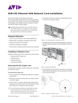
The NXA-RGB (FIG. 1) is an RGB/VGA plug-in interface card (FG2260)
that allows any of AMX’s VG-Series Modero Touch Panels to accept either
RGB or HDTV Component signals directly from an external source when
routed through an optional NXA-AVB/RGB Breakout Box. This card is field
upgradeable and works in-tandem with the RGB connector on the front of
an NXA-AVB/RGB Breakout Box.
The NXA-RGB card is an optional accessory that can be added to any
VG-Series Modero panel as part of an upgrade kit. The NXA-RGB card is a
daughter card that plugs into the Modero’s main board. This card provides
the ability to display computer graphics (RGB) or component (YCrCb) video
within a full screen or resizeable on-screen window on the Modero panel.
Specifications
Supported Component/VGA Video Resolutions and Formats
RGB RJ-45 Connection and Wiring
This RJ-45 connector is used to route the signals connected to the
RGB / Component input port on the rear of the AVB/RGB Breakout Box to
the VG-Series Modero panel. A standard CAT5 cable can be used for this
connection with short cable runs under 50 feet (15.24 m). For cable runs
over 50 feet (15.24 m), AMX recommends using the Belden Brilliance
VideoTwist 7987. This Belden cable is not CAT5 compliant, but is designed
to control skew between the red, green, and blue video signals. Therefore,
for longer cable runs, the video quality will be much higher using the Belden
VideoTwist 7987 cable versus standard CAT5 (or other Ethernet compliant
cables). The pinout of this RGB connector is given in the table below.
Note: It is important that the correct pairing is observed.
Installation of the NXA-RGB Card within a Table Top Panel
These procedures involve removing the outer housing, installing the card,
and then securely replacing the outer housing back onto the NXT panel.
Step 1: Removing the existing NXT Outer Housing
1. Carefully detach all connectors from the rear of the touch panel.
2. Gently place the touch panel LCD facedown onto a soft cloth to
expose the under-side of the base (FIG. 2) and prevent scratching of
the LCD. Tilt the base forward to provide easy access to the flat-head
and pan-head Housing Screws.
FIG. 1
NXA-RGB RGB/VGA interface card (installed within a VG-Series panel)
NXA-RGB Specifications
Dimensions (HWD): • 0.88" x 3.50" x 6.50" (2.22 cm x 8.89 cm x 16.51 cm)
Weight: • 0.85 lbs (0.39 kg)
Power: • 240 mA @ 12 VDC
Certifications: • FCC, CE, and EN60950
Features: • Accepts RGB or Component inputs (via NXA-AVB/RGB)
• Included with 1200VG/1500VG/1700VG RGB Kits
• Integrates output of keyboard and mouse data via RGB port
• On-screen RGB display window is resizeable (all the way up to full
screen)
• Provides RGB connectivity to the panel over CAT5 cables up to 200 ft.
(60.9 m)
• Receives VGA and Component video signals from the RGB connector
on the front of the NXA-AVB/RGB Breakout Box.
• Routes RGB and computer control pass-thru signals from the USB
connectors on the Modero panel to the RGB connector on the front of
the NXA-AVB/RGB Breakout Box.
Availability • This component is available separately or as part of NXA-RGBKIT
upgrade kit (FG2255-11) for Modero VG-Series touch panels.
Connector: • RJ-45 connector provides RGB/Component video signals (being routed
from the rear RGB/Component input ports) and touch control
information to the RJ-45 RGB connector on the NXA-RGB card
(installed within the panel).
Included
Accessories:
• Five pan-head securing screws
• NXA-AVB Modero RGB/VGA Interface Card QSG (93-2260)
• This unit is also available within the NXA-RGBKit (FG2255-11):
- NXA-AVB/RGB Breakout Box (FG2254-11)
- NXA-MTC/RGB Combo Table Top cable (CA2250-70)
- NXA-RGB internal RGB/VGA card (FG2260)
- NXA-RGBCBL, 15-pin to 5X BNC RGB Breakout cable (FG2250-80)
- NXT Table Top replacement I/O plate (with RGB connector opening)
(62-2250-59)
- NXD WallMount replacement adhesive overlay for existing I/O plate
(53-2250-03)
Optional
Accessories:
• Included within the RGB Kit (FGxxxx-xxRGB) is the following:
- Modero VG Touch Panel (NXD/NXT-1200/1500/1700VG)
- NXA-AVB/RGB Breakout Box (FG2254-11)
- NXA-MTC/RGB Combo Table Top cable - VG-Series panels
(CA2250-70)
- NXA-PCI80211G (FG2255-04) (Table Top Kits ONLY)
- NXA-RGB internal RGB/VGA card (FG2260)
- NXA-RGBCBL, 15-pin to 5X BNC RGB Breakout cable (FG2250-80)
• NXA-AVB/RGB Breakout Box (FG2254-11)
• NXA-MTC/RGB Modero cable (CA2250-70)
• NXA-RGBCBL, 15-pin to 5X BNC RGB Breakout cable (FG2250-80)
• PSN6.5 power supply (FG423-41)
NXA-RGB Supported Resolutions and Formats
Resolutions Refresh Rates Descriptions
VGA Compatible signals:
560 x 192 60 Hz • Apple II
560 x 384 60 Hz • MAC 12”
640 x 350 60 Hz • EGA HP 12”
640 x 416 60 Hz • DOS machines
640 x 480 60 Hz, 72 Hz, 75 Hz, 85 Hz •VGA
720 x 532 60 Hz • IBM 3472
800 x 600 60 Hz, 72 Hz, 75 Hz, 80 Hz •SVGA
900 x 720 60 Hz • Power PC 7 and Power PC 8
1024 x 768 60 Hz, 70 Hz, 75 Hz, 85 Hz •XGA
1280 x 768 60 Hz, 70 Hz, 75 Hz, 85 Hz •WXGA
1280 x 800 60 Hz, 70 Hz, 75 Hz, 85 Hz •WXGA
1152 x 864 60 Hz, 70 Hz, 75 Hz •XGA
1280 x 1024 60 Hz, 75 Hz, 85 Hz •SXGA
1600 x 1200 60 Hz •UXGA
Component/HDTV
Compatible signals:
720 x 483 • HD 480p - SMPTE 293M
1280 x 720 • HD 720p - SMPTE 296M
1920 x 1080 • HD 1080i - SMPTE 27 4M
RGB RJ-45 Connector Pinouts and Signals
Pin Color Function Polarity
1 Orange-White Blue Video -
2 Orange Blue Video +
3 Green-White Data
(bidirectional)
-
4 Blue Green Video -
5 Blue-White Green Video +
6Green Data
(bidirectional)
+
7 Brown-White Red Video -
8 Brown Red Video +
TIA 568B

AMX Corporation reserves the right to alter specifications without notice at any time.
For full warranty information, refer to the AMX Instruction Manual(s) associated with your Product(s).
036-004-2851 0*/05 ©2005
AMX Corporation. All rights reserved. The AMX logo is a trademark of AMX Corporation. AMX reserves the right to alter specifications without notice at any time.
3000 RESEARCH DRIVE, RICHARDSON, TX 75082 • 800.222.0193 • 469.624.7153 • fax 469.624.7153 • technical support 800.932.6993 • www.amx.com
93-2260
REV: C
3. While holding the outer housing and base plate at a 45°, use a
grounded Phillips-head screwdriver to remove the eight Housing
Screws.
4. Rotate the panel back over (while gripping the entire unit with outer
housing) and rest the base on a flat surface.
5. Tilt the LCD backward to a 45° angle.
6. In a single motion, carefully pull the outer housing up and then out
(away from the LCD panel) to expose the internal circuit board
(FIG. 3).
7. Unscrew the Stereo Output nut from the Stereo Output jack.
8. Firmly grab the existing connector plate and slide it up and away from
the base. This part is later replaced with the RGB connector plate.
Step 2: Installing RGB Card Components
1. Discharge any static electricity from your body by touching a
grounded metal object.
2. Locate the RGB card’s slot connector on the main board and align it
with its counterpart on the bottom of the NXA-RGB card.
3. Carefully, but firmly, insert the NXA-RGB card into the RGB
connector slot on the main board until both the card rests atop the
four raised securing holes and the RGB RJ-45 connector is evenly
aligned with the other RJ-45 connectors on the back of the panel.
4. Use a grounded Phillips-head screwdriver to secure the four
NXA-RGB pan-head securing screws to the raised securing holes on
the main board.
Step 3: Replacing the NXT Outer Housing
1. Obtain the new RGB I/O connector plate (similar to the original but
containing the added RGB connector opening to the newly installed
NXA-RGB) and slide it back into position.
2. Resecure the Stereo Output nut back onto the new RGB I/O plate.
3. Once the RGB card has been installed, tilt the LCD back to a 45° and
then gently slide-on the outer housing (towards the LCD) until the it is
aligned over the installation holes and the tilt bracket prevents any
further forward movement (FIG. 3).
4. Gently press down on the housing (toward the base) until it is
securely positioned over the circuit board and covers base.
5. While holding the outer housing and base plate in place, turn the
panel back over until the LCD lies facedown on a soft cloth and the
under-side of the base is exposed.
6. Insert and secure the eight Housing Screws (using a grounded
Phillips-head screwdriver) into their respective locations (FIG. 2).
7. Grasp both the LCD and housing, then rotate the entire unit back
onto a flat surface then insert all connectors and apply power.
Installation of the NXA-RGB Card within a WallMount Panel
These procedures involve upgrading an NXD with a new NXA-RGB card.
Step 1: Removing the existing NXD Outer Housing
1. Carefully detach all connectors from the side of the touch panel and
remove the front magnetic faceplate from the NXD unit by firmly
gripping the faceplate and pulling outwards, while applying a small
amount of pressure to remove it from the main unit.
2. Place the LCD facedown onto a soft cloth to expose the under-side of
the unit and prevent scratching of the LCD.
3. Unscrew the Stereo Output nut from the Stereo Output jack.
4. Remove the I/O connector plate by using a grounded Phillips-head
screwdriver to remove the two screws and slide the I/O connector
plate away from the back box housing.
5. Unscrew the four pan-head Housing Screws from the rear of the
NXD unit (FIG. 4) and gently remove the outer housing. These four
screws secure the back box to the internal panel casing.
6. To install the NXA-RGB card onto the NXD main board, use the
procedures outlined in the previous Step 2: Installing RGB Card
Components section.
Step 3: Replacing the NXD Outer Housing
1. Once the card has been securely installed, gently place the outer
housing back onto the metallic panel casing (with the connector
opening on the right-side of the panel) and align the four pan-head
Housing Screw holes along the edges of the outer housing.
Note: Use care not to bend or damage any antenna connections
while replacing the outer housing.
2. Insert and secure the four pan-head Housing Screws into the
pre-drilled holes along the edges of the NXD unit by using a
grounded Phillips-head screwdriver.
3. Remove the previous I/O plate adhesive overlay (this reveals a
pre-drilled RGB connector opening) and replace it with the new
adhesive RGB overlay (53-2250-03).
4. Reinstall the upgraded RGB I/O connector plate by aligning all
connectors to their respective locations.
5. Secure the I/O plate using a grounded Phillips-head screwdriver and
then twist the nut back onto the Stereo Output jack.
FIG. 2
Location of the attachment screws on an NXT panel
FIG. 3 Location of the NXA-RGB card and I/O plate
Unscrew these
eight Housing
Screws to remove
the circuit board
housing
DO NOT
REMOVE
these screws
They secure
the speakers
to the main
board
Base plate
Outer housing
45°
RGB I/O
NXA-RGB card
Outer Housing
NXA-RGB card
screw locations (4)
connector plate
FIG. 4
Location of the securing screws on an NXD panel
DO NOT
REMOVE
these
4 panel
securing
screws
Unscrew these
4 pan-head
Housing Screws
to remove the
back box. These
make direct contact
with the black
outer housing
/