LG DLG3171W Owner's manual

Category
Electric laundry dryers
Type
Owner's manual
ENGLISH
FRANÇAIS
OWNER'S MANUAL
DRYER
Read this owner's manual thoroughly before operating the appliance
and keep it handy for reference at all times.
MFL67731029
Rev.12_071117
DLE3170*, DLG3171*
DLEX3370*, DLGX3371*
DLEX3570*, DLGX3571*
DLE3075*, DLE3180*
www.lg.com
Copyright © 2014 - 2017 LG Electronics Inc. All Rights Reserved.
2
TABLE OF CONTENTS
3 PRODUCT FEATURES
4 SAFETY INSTRUCTIONS
5 IMPORTANT SAFETY INSTRUCTIONS
9 PRODUCT OVERVIEW
9 Parts
9 Accessories
10 INSTALLATION
10 Installation Overview
10 Product Specifications
11 Installation Location Requirements
12 Clearances
14 Leveling the Dryer
15 Reversing the Door
16 Installing the Side Vent Kit
17 Stacking the Dryer
18 Venting the Dryer
19 Connecting Gas Dryers
21 Connecting Electric Dryers
22 Special Electrical Requirements
22 Final Installation Check
23 Installation Test (Duct Check)
26 OPERATION
26 Using the Dryer
27 Check the Lint Filter Before Every Load
27 Sorting Laundry
27 Loading the Dryer
28 Control Panel
31 Cycle Guide
35 Cycle Modifier Buttons
35 Option Buttons
36 Special Functions
37 Steam Functions (Steam Models)
40 SMART FUNCTIONS
40 Smart ThinQ Application
41 Smart Diagnosis™ Function
42 MAINTENANCE
42 Regular Cleaning
43 TROUBLESHOOTING
43 FAQs: Frequently Asked Questions
44 Before Calling for Service
51 WARRANTY
3PRODUCT FEATURES
ENGLISH
PRODUCT FEATURES
Easy-to-Use Control Panel
Rotate the cycle selector knob to select the desired dry cycle. Add cycle options or adjust settings with the
touch of a button.
Easy-Access Reversible Door
The wide-opening door provides easy access for loading and unloading. The door hinge can be reversed to
adjust for installation location.
Steam Functions (Steam Models)
LG’s steam technology allows you to inject fabrics with a swirling jet of hot steam to refresh clothes, reduce
static, and make ironing easier. Simply select the Steam Fresh™ cycle, or you can add a Steam option to
selected cycles.
Flow Sense™ Duct Blockage Sensing System Indicator
The Flow Sense™ duct blockage sensing system detects and alerts you to restrictions in the installed
household ductwork that reduce exhaust airow through the dryer. If you see the alert: Clean or repair the
ducts to remove the restrictions. Keep your ducts clean to help increase efciency and reduce long drying
times caused by blocked ducts.
Smart Diagnosis™
Should you experience any technical difculty with your dryer, it has the capability of transmitting data via your
telephone to the Customer Information Center. The call center agent records the data transmitted from your
machine and uses it to analyze the issue, providing a fast and effective diagnosis.
Tag On (On Some Models)
The Tag On feature works on most NFC equipped smartphones by communicating with a Tag On equipped LG
appliance. Using the LG Smart ThinQ application, the Tag On feature will allow you to diagnose your appliance,
download new cycles, and see the status of your appliance by simply touching the smartphone to the Tag On
logo of the appliance.
C
E
R
T
I
F
I
E
D
D
E
S
I
G
N
Protocol P154 Sanitization
Performance of Residential Clothes
dryer
4 SAFETY INSTRUCTIONS
SAFETY INSTRUCTIONS
READ ALL INSTRUCTIONS BEFORE USE
Your safety and the safety of others are very important.
We have provided many important safety messages in this manual and on your appliance. Always read and
follow all safety messages.
This is the safety alert symbol.
This symbol alerts you to potential hazards that can kill or injure you and others.
All safety messages will follow the safety alert symbol and either the word WARNING or CAUTION.
These words mean:
WARNING
You may be killed or seriously injured if you do not follow instructions.
CAUTION
You may be slightly injured or cause damage to the product if you do not follow instructions.
All safety messages will tell you what the potential hazard is, tell you how to reduce the chance of injury, and
tell you what may happen if the instructions are not followed.
WARNING- Risk of Fire
Install the clothes dryer according to the manufacturer’s instructions and local codes.
Clothes dryer installation must be performed by a qualied installer.
Do not install a clothes dryer with exible plastic venting materials. If exible metal (foil type) duct is installed,
it must be of a specic type identied by the appliance manufacturer as suitable for use with clothes dryers.
Flexible venting materials are known to collapse, be easily crushed, and trap lint. These conditions will obstruct
clothes dryer airow and increase the risk of re.
To reduce the risk of severe injury or death, follow all installation instructions.
Save these instructions.
WARNING
FIRE OR EXPLOSION HAZARD
Failure to follow safety warnings exactly could result in serious injury, death or property damage.
Do not store or use gasoline or other ammable vapors and liquids in the vicinity of this or any other
appliance.
WHAT TO DO IF YOU SMELL GAS
- Do not try to light any appliance.
- Do not touch any electrical switch; do not use any phone in your building.
- Clear the room, building or area of all occupants.
- Immediately call your gas supplier from a neighbor’s phone. Follow the gas supplier’s instructions.
- If you cannot reach your gas supplier, call the re department.
Installation and service must be performed by a qualied installer, service agency or your gas supplier.
5SAFETY INSTRUCTIONS
ENGLISH
IMPORTANT SAFETY INSTRUCTIONS
WARNING
To reduce the risk of explosion, re, death, electric shock, scalding or injury
to persons when using this product, follow basic precautions, including the
following:
INSTALLATION
Before use, the appliance must be properly installed as described in this manual.
Connect to a properly rated, protected, and sized power circuit to avoid electrical overload.
To reduce the risk of severe injury or death, follow all installation instructions.
The appliance must be installed and electrically grounded by qualied service personnel in accordance with
local codes.
Disconnect the power cord, house fuse or circuit breaker before installing or servicing the appliance.
When moving or installing the product in a different location, call qualied service personnel for installation
and service.
Keep packing materials out of the reach of children. Packaging material can be dangerous for children.
There is a risk of suffocation.
Moving or installation of the appliance requires two or more people.
This appliance is not designed for maritime use or for mobile installations such as in RVs, trailers, or aircraft.
Store and install the appliance where it will not be exposed to temperatures below freezing or exposed to
outdoor weather conditions.
This appliance must be positioned near to an electrical power supply.
Do not, under any circumstances, cut or remove the third (ground) prong from the power cord.
When installing or moving the appliance, be careful not to pinch, crush, or damage the power cord.
Do not install the appliance in humid spaces.
Destroy the carton, plastic bag, and other packing materials after the appliance is unpacked. Children might
use them for play. Cartons covered with rugs, bedspreads, or plastic sheets can become airtight chambers.
Adhere to all industry recommended safety procedures including the use of long sleeved gloves and safety
glasses.
Never attempt to operate this appliance if it is damaged, malfunctioning, partially disassembled, or has
missing or broken parts, including a damaged cord or plug.
Do not install a clothes dryer with exible plastic venting materials. If exible metal (foil type) duct is
installed, it must be of a specic type identied by the appliance manufacturer as suitable for use with
clothes dryers. Flexible venting materials are known to collapse, be easily crushed, and trap lint. These
conditions will obstruct clothes dryer airow and increase the risk of re.
6 SAFETY INSTRUCTIONS
Place the dryer at least 18 inches above the oor for a garage installation.
Do not use sheet metal screws or other fasteners which extend into the duct that could catch lint and reduce
the efciency of the exhaust system. Secure all joints with duct tape.
Use only rigid, semi-rigid or exible metal 4-inch diameter duct inside the dryer cabinet or for exhausting to
the outside. Use of plastic or other combustible ductwork may cause re. Punctured ductwork may cause
re if it collapses or becomes otherwise restricted in use or during installation.
The exhaust duct must be 4 inches (10.2 cm) in diameter with no obstructions. The exhaust duct should be
kept as short as possible. Make sure to clean any old ducts before installing your new dryer.
Rigid, semi-rigid or exible metal ducting is recommended for use between the dryer and the wall. All non-
rigid metal transition duct must be UL-listed. Use of other materials for transition duct could affect drying
time.
Ductwork is not provided with the dryer, and you should obtain the necessary ductwork locally. The end cap
should have hinged dampers to prevent backdraft when the dryer is not in use.
Gas dryers MUST be exhausted to the outside.
The dryer exhaust system must be exhausted to the outside of the dwelling. If the dryer is not exhausted
outdoors, some ne lint and large amounts of moisture will be expelled into the laundry area. An
accumulation of lint in any area of the home may create a health and re hazard.
Do not install near another heat source such as a stove, oven or heater.
Keep area around the exhaust opening and adjacent surrounding areas free from the accumulation of lint,
dust, and dirt.
OPERATION
Repair or immediately replace all power cords that have become frayed or otherwise damaged. Do not use
a cord that shows cracks or abrasion damage along its length or at either end.
If you detect a strange sound, a chemical or burning smell, or smoke coming from the appliance, unplug it
immediately, and contact an LG Electronics customer information center.
Never unplug the appliance by pulling on the power cord. Always grip the plug rmly and pull straight out
from the outlet.
Do not use an extension cord or adapter with this appliance.
Do not grasp the power cord or touch the appliance controls with wet hands.
Do not modify or extend the power cord.
If the product has been submerged, contact an LG Electronics customer information center for instructions
before resuming use.
Do not store or use gasoline or other ammable vapors and liquids in the vicinity of this or any other
appliance.
Keep the area underneath and around your appliances free of combustible materials (lint, paper, rags, etc.),
gasoline, chemicals and other ammable vapors and liquids.
This appliance is not intended for use by persons (including children) with reduced physical, sensory or
mental capabilities, or lack of experience and knowledge, unless they have been given supervision or
instruction concerning the use of the appliance by a person responsible for their safety.
7SAFETY INSTRUCTIONS
ENGLISH
Read all instructions before using the appliance and save these instructions.
Use this appliance only for its intended purpose.
Do not abuse, sit on, or stand on the door of the appliance.
Do not allow children to play on, in or with the appliance. Close supervision of children is necessary when
the appliance is used near children.
Do not tamper with controls.
In the event of a gas leak (propane gas, LP gas, etc.) do not operate this or any other appliance. Open a
window or door to ventilate the area immediately.
Under certain conditions, hydrogen gas may be produced in a hot-water system that has not been used
for two weeks or more. HYDROGEN GAS IS EXPLOSIVE. If the hot-water system has not been used for
such a period, before using the appliance turn on all hot water faucets and let the water ow from each for
several minutes. This will release any accumulated hydrogen gas. As the gas is ammable, do not smoke or
use an open ame during this time.
Fix the drain hose securely in place.
Do not put oily or greasy clothing, candles or ammable materials on top of the appliance.
Do not use fabric softeners or products to eliminate static unless recommended by the manufacturer of the
fabric softener or product.
Do not reach into the appliance if the drum is moving.
Do not dry articles that have been previously cleaned in, washed in, soaked in, soiled with or spotted with
gasoline, dry cleaning solvents, vegetable oil, cooking oil or other ammable or explosive substances, as
they give off vapors that could ignite or explode.
Do not use heat to dry articles containing foam rubber or similarly textured rubber-like materials.
Do not store plastic, paper, or clothing that may burn or melt on top of the dryer during operation.
Always check the inside of the appliance for foreign objects.
Gas appliances can cause minor exposure to four of these substances, namely benzene, carbon monoxide,
formaldehyde, and soot, caused primarily by the incomplete combustion of natural gas or LP fuels.
Properly adjusted dryers will minimize incomplete combustion. Exposure to these substances can be
minimized further by properly venting the dryer to the outdoors.
STEAM (Steam models)
Do not open the dryer door during STEAM CYCLE.
Do not touch the steam nozzle in the drum during or after the STEAM CYCLE.
Do not ll the steam feeder with hot water (over 86 °F/ 30 °C), gasoline, dry cleaning solvents, or other
ammable or explosive substances.
8 SAFETY INSTRUCTIONS
MAINTENANCE
Do not repair or replace any part of the appliance. All repairs and servicing must be performed by qualied
service personnel unless specically recommended in this Owner’s Manual. Use only authorized factory
parts.
Do not disassemble or repair the appliance by yourself.
Remove any dust or foreign matter from the power plug pins.
Disconnect this appliance from the power supply before cleaning and attempting any user maintenance.
Turning the controls to the OFF position does not disconnect this appliance from the power supply.
Remove the door before the appliance is removed from service or discarded to avoid the danger of children
or small animals getting trapped inside.
Unplug the appliance before cleaning to avoid the risk of electric shock.
Clean the lint lter before or after each load.
The interior of the appliance and exhaust duct should be cleaned periodically by qualied service personnel.
GROUNDING INSTRUCTIONS
Improper connection of the equipment-grounding conductor can result in a risk of electric shock. Check with
a qualied electrician or service personnel if you are in doubt whether the appliance is properly grounded.
Do not modify the plug provided with the appliance; if it will not t the outlet, have a proper outlet installed by
a qualied electrician.
The appliance must be grounded. In the event of a malfunction or breakdown, grounding will reduce the risk
of electric shock by providing a path of least resistance for electric current. The appliance is equipped with
a cord having an equipment-grounding conductor and a grounding plug. The plug must be plugged into an
appropriate outlet that is installed and grounded in accordance with all local codes and ordinances.
This dryer must be plugged into a properly grounded outlet. Electrical shock may result if the dryer is not
properly grounded. Have the wall outlet and circuit checked by a qualied electrician to make sure the outlet
is properly grounded. Failure to follow these instructions may create an electric shock hazard and/or a re
hazard.
WARNING
Fire Hazard
Failure to follow safety warnings exactly could result in serious injury, death or
property damage.
Do not install a booster fan in the exhaust duct.
Install all clothes dryers in accordance with the installation instructions of the manufacturer of the dryer.
SAVE THESE INSTRUCTIONS
9PRODUCT OVERVIEW
ENGLISH
PRODUCT OVERVIEW
Parts
Control panel
Lint lter
Leveling feet
Reversible
door
Power Cord
(gas models)
Gas connection
(gas models)
Exhaust Duct Outlet
Terminal Block
Access Panel
(electric models)
Accessories
Included Accessories
Drying Rack
(on some models)
Optional Accessories
Pedestal (sold separately) Stacking kit (sold separately)
NOTE
For your safety and extended product life, use only authorized components. The manufacturer is not
responsible for product malfunction or accidents caused by the use of unauthorized components or parts.
The images in this manual may be different from the actual components and accessories that are subject to
change by the manufacturer without prior notice for product improvement purposes.
10 INSTALLATION
INSTALLATION
Installation Overview
Please read the following installation instructions rst after purchasing this product or transporting it to another
location.
Check and choose the
proper location
Level the dryer Vent the dryer
Connect the Gas dryer Connect the Electric dryer Gas dryer Electric dryer
Plug in the power cord
Installation test Test run
Product Specications
The appearance and specications listed in this manual may vary due to constant product improvements.
Dryer Models
DLE3170*/
DLG3171*/
DLE3075*/
DLE3180*
DLEX3370*/
DLGX3371*
DLEX3570*/
DLGX3571*
Description Non-steam Dryer Steam Dryer Steam Dryer
Electrical requirements Please refer to the rating label for detailed information.
Gas requirements
NG: 4 - 10.5-inch (10.2 - 26.7 cm) WC
LP: 8 - 13-inch (20.4 - 33.1 cm) WC
Dimensions
27” (W) X 30” (D) X 38.7” (H), 51.4” (D with door open)
68.6 cm (W) X 76.1 cm (D) X 98.3 cm (H), 130.5 cm (D with door
open)
Net weight
Gas : 124.7 lb (56.6 kg) - 137.5 lb (62.4 kg)
Electric : 122.0 lb (55.3 kg) - 134.1 lb (60.8 kg)
Drying capacity
Steam Cycle - IEC 7.4 cu.ft. (8 lb/3.6 kg)
Normal Cycle IEC 7.4 cu.ft. (22.5 lb/10.2 kg)
11INSTALLATION
ENGLISH
Installation Location Requirements
WARNING
Read all installation instructions completely before installing and operating your dryer! It is important that
you review this entire manual before installing and using your dryer. Detailed instructions concerning
electrical connections, gas connections, and exhaust requirements are provided on the following pages.
The installation requires:
A location that allows for proper exhaust installation. A gas dryer must be exhausted to the outdoors. See
Venting the Dryer.
A grounded electrical outlet located within 2 ft. (61 cm) of either side of the dryer. See Connecting Electric
Dryers.
A sturdy oor to support the total dryer weight of 200 lb (90.7 kg). The combined weight of a companion
appliance should also be considered.
No other fuel-burning appliance can be installed in the same closet as a dryer.
Additional clearances might be required for wall, door and oor moldings.
Companion appliance spacing should also be considered.
NOTE
The oor must be level, with a maximum slope of 1 inch (2.5 cm) under the entire dryer. Clothes may not
tumble properly, and automatic sensor cycles may not operate correctly if the dryer is not level.
For garage installation, you will need to place the dryer at least 18-inch (46 cm) above the oor. The standard
pedestal is 15-inch (38 cm). You will need 18-inch (46 cm) from the garage oor to the bottom of the dryer.
Do not operate your dryer at temperatures below 45 °F (7 °C). At lower temperatures, the dryer might not shut
off at the end of an automatic cycle. This can result in longer drying times.
The dryer must not be installed or stored in an area where it will be exposed to water and/or weather.
Check code requirements that limit, or do not permit, installation of the dryer in garages, closets, mobile homes
or sleeping quarters. Contact your local building inspector.
12 INSTALLATION
Clearances
1"*
(25 mm)
14" max.*
(356 mm)
18" min.*
(457 mm)
14" max.*
(356 mm)
18" min.*
(457 mm)
30"
(761mm)
5"**
(127 mm)
1"*
(25 mm)
30"
(761mm)
5"**
(127 mm)
24 in.
2*
(155 cm
2
)
2*
(310 cm
2
)
3"
*
(76 mm)
48 in.
3"
*
(76 mm)
1"
(25 mm)
1"
(25 mm)
27"
(686 mm)
0"
(0 mm)
39"
(991 mm)
1"
(25 mm)
1"
(25 mm)
27"
(686 mm)
Closet Door
Vent Requirements
Installation Spacing for Recessed Area or Closet Installation
The following spacing dimensions are recommended for this dryer. This dryer has been tested for clearances
of 1 inch (2.5 cm) on the sides and rear. Recommended clearances should be considered for the following
reasons:
Additional clearances should be considered for ease of installation and servicing.
Additional clearances should be considered on all sides of the dryer to reduce noise transfer. For closet
installation, with a door, minimum ventilation openings in the top and bottom of the door are required. Louvered
doors with equivalent ventilation openings are acceptable.
Closet Ventilation Requirements
Closets with doors must have both an upper and lower vent to prevent heat and moisture buildup in the closet.
One upper vent opening with a minimum opening of 48 sq. in. (310 cm
2
) must be installed no lower than 6 feet
above the oor. One lower vent opening with a minimum opening of 24 sq. in. (155 cm
2
) must be installed no
more than one foot above the oor. Install vent grills in the door or cut down the door at the top and bottom to
form openings. Louvered doors with equivalent ventilation openings are also acceptable.
NOTE
There should be at least a little space around the dryer (or any other appliance) to eliminate the transfer of
vibration from one appliance to another. If there is enough vibration, it could cause appliances to make noise or
come into contact, causing paint damage and further increasing noise.
13INSTALLATION
ENGLISH
Installation Spacing for Recessed Area or Closet, with Stacked Washer and
Dryer
24 in.
2*
(155 cm
2
)
2*
(310 cm
2
)
48 in.
3"
*
(76 mm)
3"
*
(76 mm)
1"*
(25 mm)
1"
(25 mm)
1"
(25 mm)
27"
(686 mm)
5 ½"
**
(140 mm)
6"
*
(152 mm)
77 ½"
(1968 mm)
* Required spacing
** For side or bottom venting, 2-inch (5.1 cm) of spacing is allowed.
Installation Spacing for Cabinet
For cabinet installation with a door, minimum ventilation openings in the top of the cabinet are required.
* Required spacing
7" *
(178 mm)
7" *
(178 mm)
9" **
(229 mm)
1"
(25 mm)
1"
(25 mm)
27"
(686 mm)
5"*
(127 mm)
1"*
(25 mm)
30"
(761 mm)
14 INSTALLATION
Leveling the Dryer
WARNING
To reduce the risk of serious injury or death,
follow basic precautions, including the
following:
Use long-sleeved gloves and safety glasses.
The appliance is heavy. Two or more people are
required when installing the dryer.
NOTE
Adjust the leveling feet only as far as necessary
to level the dryer. Extending the leveling feet more
than necessary may cause the dryer to vibrate.
To ensure that the dryer provides optimal drying
performance, it must be level. To minimize vibration,
noise, and unwanted movement, the oor must be a
perfectly level, solid surface.
1
Position the dryer in the nal location. Place a
level across the top of the dryer.
Level
Leveling Feet
• All four leveling feet must rest solidly on the
oor. Gently push on the top corners of the
dryer to make sure that the dryer does not rock
from corner to corner.
NOTE
If you are installing the dryer on the optional
pedestal, you must use the leveling feet on the
pedestal to level the dryer. The dryer leveling feet
should be fully retracted.
2
Use an adjustable wrench to turn the leveling
feet. Unscrew the legs to raise the dryer or
screw the legs to lower it. Raise or lower with
the leveling feet until the dryer is level from side
to side and front to back. Make sure that all four
leveling feet are in rm contact with the oor.
15INSTALLATION
ENGLISH
Reversing the Door
Tools Required
Phillips screwdriver
Large at blade screwdriver (recommended for
hinge screws if they are tight or your Phillips
screwdriver is worn)
Small at blade screwdriver (for lifting out parts)
WARNING
To reduce the risk of damage to the dryer,
property damage or personal injury, follow
basic precautions, including the following:
Support the door with a stool or box that ts
under the door, or have an assistant support the
weight of the door.
Avoid dropping the door.
Unplug the dryer or turn off power at the main
circuit breaker before beginning door reversal.
Always reverse the door BEFORE stacking the
dryer on top of the washer.
Door Reversal Instructions
The instructions here are for changing the door swing
from a right to a left side hinge. If the door has been
reversed, and it is necessary to change it back, use
care when following these instructions. Some of
the illustrations and the left/right references will be
reversed, and you will need to read the instructions
carefully.
WARNING
Be sure to support the weight of the door before
removing the hinge screws.
1
Open the door and remove the two decorative
screws, two latch screws, and the latch on the
catch side with a screwdriver. Save these for
step 4.
2
While supporting the door, remove the 2 screws
on the door hinge. Remove the door.
3
Turn the door upside down and line up the
holes in the hinge with the holes in the cabinet.
Reinstall the door with the screws removed in
step 2.
WARNING
Be sure to support the weight of the door before
installing the hinge screws.
4
Install the two decorative screws, the latch,
and two latch screws removed in step 1 on the
opposite side from which they were removed.
5
Check that the door closes properly.
16 INSTALLATION
Installing the Side Vent Kit
WARNING
To reduce the risk of serious injury, death or
property damage, follow basic precautions,
including the following:
Use long-sleeved gloves and safety glasses.
Use a heavy metal vent.
Do not use plastic or thin foil ducts.
Clean old ducts before installing this dryer.
Your new dryer is congured to vent to the rear. It can
also vent to the bottom or side (right-side venting is
not available on gas models).
An adapter kit, part number 383EEL9001B, may be
purchased from your LG retailer. This kit contains
duct components necessary to change the dryer vent
location.
1
Remove the rear exhaust duct retaining screw.
Pull out the exhaust duct.
Retaining Screw
Rear Exhaust Duct
Option 1: Side Venting
2
Press the tabs on the knockout and carefully
remove the knockout for the desired vent
opening (right-side venting is not available on
gas models). Press the adapter duct onto the
blower housing and secure to the base of the
dryer as shown.
Adapter Duct
Bracket
Knockout
3
Preassemble a 4-inch (10.2 cm) elbow to the
next 4-inch (10.2 cm) duct section, and secure
all joints with duct tape. Be sure that the male
end of the elbow faces AWAY from the dryer.
Insert the elbow/duct assembly through the
side opening and press it onto the adapter duct.
Secure it in place with duct tape. Be sure that
the male end of the duct protrudes 1.5-inch (3.8
cm) to connect the remaining ductwork. Attach
the cover plate to the back of the dryer with the
included screw.
Cover Plate
Elbow
1½" (38 mm)
Option 2: Bottom Venting
2
Press the adapter duct onto the blower housing
and secure it to the base of the dryer as shown.
Adapter Duct
Bracket
3
Insert the 4-inch (10.2 cm) elbow through the
rear opening and press it onto the adapter duct.
Be sure that the male end of the elbow faces
down through the hole in the bottom of the
dryer. Secure it in place with duct tape. Attach
the cover plate to the back of the dryer with the
included screw.
Cover Plate
Elbow
17INSTALLATION
ENGLISH
Stacking the Dryer
Stacking Kit Installation
This stacking kit includes:
Two (2) side rails
One (1) front rail
Four (4) screws
Tools Needed for Installation:
Phillips screwdriver
WARNING
To reduce the risk of electrical shock, re,
explosion, property damage, serious injury or
death, follow basic precautions, including the
following:
The weight of the dryer and the height of
installation make this stacking procedure too
risky for one person. Two or more people are
required when installing the stacking kit.
Do not use the stacking kit with a gas dryer in
potentially unstable conditions such as a mobile
home.
Place the washer on a solid, stable, level
oor capable of supporting the weight of both
appliances.
Do not stack the washer on top of the dryer.
If appliances are already installed, disconnect
them from all power, water, or gas lines and from
draining or venting connections.
To ensure safe and secure installation, please
observe the following instructions.
1
Make sure the surface of the washer is clean
and dry. Remove paper backing from the tape
on one of the stacking kit side brackets.
2
Fit the side bracket to the side of the washer top
as shown in the above illustration. Firmly press
the adhesive area of the bracket to the washer
surface. Secure the side bracket to the washer
with a screw on the back side of the bracket.
Repeat steps 1 and 2 to attach the other side
bracket.
3
Place the dryer on top of the washer by
tting the dryer feet into the side brackets as
illustrated. Avoid nger injuries; do not allow
ngers to be pinched between the washer and
dryer.
Slowly slide the dryer toward the back of the
washer until the side bracket stoppers catch the
dryer feet.
4
Insert the front rail between the bottom of the
dryer and the top of the washer. Push the front
rail toward the back of the washer until it comes
in contact with the side rail stoppers.
Install the two remaining screws to secure the
front rail to the side rails.
18 INSTALLATION
Venting the Dryer
WARNING
To reduce the risk of re or explosion, electric
shock, property damage, injury to persons or
death when using this appliance, follow basic
safety precautions, including the following:
Do not crush or collapse ductwork.
Do not allow ductwork to rest on or contact sharp
objects.
If connecting to existing ductwork, make sure it is
suitable and clean before installing the dryer.
Venting must conform to local building codes.
Gas dryers MUST exhaust to the outdoors.
Use only 4-inch (10.2 cm) rigid, semi-rigid or
exible metal ductwork inside the dryer cabinet
and for venting outside.
To reduce the risk of re, combustion, or
accumulation of combustible gases, DO
NOT exhaust dryer air into an enclosed and
unventilated area, such as an attic, wall, ceiling,
crawl space, chimney, gas vent, or concealed
space of a building.
To reduce the risk of re, DO NOT exhaust the
dryer with plastic or thin foil ducting.
The exhaust duct must be 4-inch (10.2 cm) in
diameter with no obstructions. The exhaust duct
should be kept as short as possible. Make sure
to clean any old ducts before installing your new
dryer.
Rigid, semi-rigid or exible metal ducting is
recommended for use between the dryer and
the wall. All non-rigid metal transition duct must
be UL-listed. Use of other materials for transition
duct could affect drying time.
DO NOT use sheet metal screws or other
fasteners which extend into the duct that could
catch lint and reduce the efciency of the
exhaust system. Secure all joints with duct tape.
Do not exceed the recommended duct length
limitations noted in the chart. Failure to follow
these instructions may result in extended drying
times, re or death.
WARNING
Ductwork is not provided with the dryer. You
should obtain the necessary ductwork locally.
The vent hood should have hinged dampers to
prevent backdraft when the dryer is not in use.
The total length of exible metal duct must not
exceed 8 ft. (2.4 m).
Ductwork
Wall Cap Type
Number
of 90°
Elbows
Maximum
length of 4-inch
diameter rigid
metal duct
Recommended
a
a
a: 4" (10.2 cm)
0 65 ft.(19.8 m)
1 55 ft.(16.8 m)
2 47 ft.(14.3 m)
3 36 ft.(11.0 m)
4 28 ft.(8.5 m)
Use only for short
run installations
b
b: 2.5" (6.35 cm)
0 55 ft.(16.8 m)
1 47 ft.(14.3 m)
2 41 ft.(12.5 m)
3 30 ft.(9.1 m)
4 22 ft.(6.7 m)
NOTE
Deduct 6 ft. (1.8 m) for each additional elbow. Do
not use more than four 90° elbows.
In Canada, only those foil-type exible ducts, if any,
specically identied for use with the appliance by
the manufacturer should be used. In the United
States, only those foil-type exible ducts, if any,
specically identied for use with the appliance by
the manufacturer and that comply with the Outline
for Clothes Dryer Transition Duct, Subject 2158A,
should be used.
19INSTALLATION
ENGLISH
Routing and Connecting Ductwork
NOTE
Follow the guidelines below to maximize drying
performance and reduce lint buildup and
condensation in the ductwork. Ductwork and
ttings are NOT included and must be purchased
separately.
Use 4-inch (10.2 cm) diameter rigid, semi-rigid or
exible metal ductwork.
The exhaust duct run should be as short as
possible.
Use as few elbow joints as possible.
The male end of each section of exhaust duct must
point away from the dryer.
Use duct tape on all duct joints.
Insulate ductwork that runs through unheated areas
in order to reduce condensation and lint buildup on
duct surfaces.
Incorrect or inadequate exhaust systems are not
covered by the dryer warranty. Dryer failures or
service required because of such exhaust systems
will not be covered by the dryer warranty.
Correct Venting
Incorrect Venting
Connecting Gas Dryers
WARNING
To reduce the risk of re or explosion, electric
shock, property damage, injury to persons,
or death when using this appliance, follow
requirements including the following:
Electrical Requirements for Gas
Models Only
Do not, under any circumstances, cut or remove
the third (ground) prong from the power cord.
For personal safety, this dryer must be properly
grounded.
This dryer must be plugged into a 120-VAC, 60-
Hz. grounded outlet protected by a 15-ampere
fuse or circuit breaker.
Where a standard 2-prong wall outlet is
encountered, it is your personal responsibility
and obligation to have it replaced with a properly
grounded 3-prong wall outlet.
ELECTRIC SHOCK HAZARD
Failure to follow safety warnings could result
in serious injury
This dryer is equipped with a three-prong
grounding plug for protection against shock
hazard and should be plugged directly into a
properly grounded three-prong receptacle. Do
not cut or remove the grounding prong from this
plug.
Gas Supply Requirements
As shipped from the factory, this dryer is
congured for use with natural gas (NG). It can
be converted for use with propane (LP) gas.
Gas pressure must not exceed 8-inch (20.4 cm)
water column for NG, or 13-inch (33.1 cm) water
column for LP.
A qualied service or gas company technician
must connect the dryer to the gas service.
Isolate the dryer from the gas supply system by
closing its individual manual shutoff valve during
any pressure testing of the gas supply.
DO NOT attempt any disassembly of the dryer;
disassembly requires the attention and tools of
an authorized and qualied service technician or
company.
Securely tighten all gas connections.
Connect the dryer to the type of gas shown on
the nameplate.
20 INSTALLATION
WARNING
Gas Supply Requirements (continued)
Supply line requirements: Your laundry room
must have a rigid gas supply line to your dryer.
In the United States, an individual manual shutoff
valve MUST be installed within at least 6 ft. (1.8
m) of the dryer, in accordance with the National
Fuel Gas Code ANSI Z223.1 or Canadian gas
installation code CSA B149.1. A 1/8-inch NPT
pipe plug must be installed.
If using a rigid pipe, the rigid pipe should be
0.5-inch IPS. If acceptable under local codes and
ordinances and when acceptable to your gas
supplier, 3/8-inch approved tubing may be used
where lengths are less than 20 ft. (6.1 m). Larger
tubing should be used for lengths in excess of 20
ft. (6.1 m).
To prevent contamination of the gas valve,
purge the gas supply of air and sediment before
connecting the gas supply to the dryer. Before
tightening the connection between the gas
supply and the dryer, purge remaining air until
the odor of gas is detected.
DO NOT use an open ame to inspect for gas
leaks. Use a noncorrosive leak detection uid.
Use only a new AGA- or CSA-certied
gas supply line with exible stainless steel
connectors.
Use Teon tape or a pipe-joint compound that is
insoluble in propane (LP) gas on all pipe threads.
Connecting the Gas Supply
Installation and service must be performed by
a qualied installer, service agency, or the gas
supplier.
Use only a new stainless steel exible connector
and a new AGA-certied connector.
A gas shutoff valve must be installed within 6 ft.
(1.8 m) of the dryer.
The dryer is congured for natural gas when
shipped from the factory. Make sure that the
dryer is equipped with the correct burner nozzle
for the type of gas being used (natural gas or
propane gas).
If necessary, the correct nozzle (for the LP
nozzle kit, order part number 383EEL3002D)
should be installed by a qualied technician and
the change should be noted on the dryer.
All connections must be in accordance with
local codes and regulations. Gas dryers MUST
exhaust to the outdoors.
NOTE
In the Commonwealth of Massachusetts: This
product must be installed by a licensed plumber
or gas tter. When using ball-type gas shut off
valves, they shall be T-handle-type. A exible gas
connector, when used, must not exceed 3 feet.
This dryer is congured from the factory for natural
gas (NG). If the dryer is to be used with propane
(LP) gas, it must be converted by a qualied service
technician.
1
Make sure that the gas supply to the laundry
room is turned OFF and the dryer is unplugged.
Conrm that the type of gas available in your
laundry room is appropriate for the dryer.
2
Remove the shipping cap from the gas tting at
the back of the dryer. Be careful not to damage
the threads of the gas connector when removing
the shipping cap.
3
Connect the dryer to your laundry room’s gas
supply using a new exible stainless steel
connector with a 3/8-inch NPT tting.
NOTE
DO NOT use old connectors.
4
Securely tighten all connections between the
dryer and your laundry room’s gas supply.
5
Turn on your laundry room’s gas supply.
6
Check all pipe connections (both internal and
external) for gas leaks with a noncorrosive leak-
detection uid.
7
Proceed to Venting the Dryer.
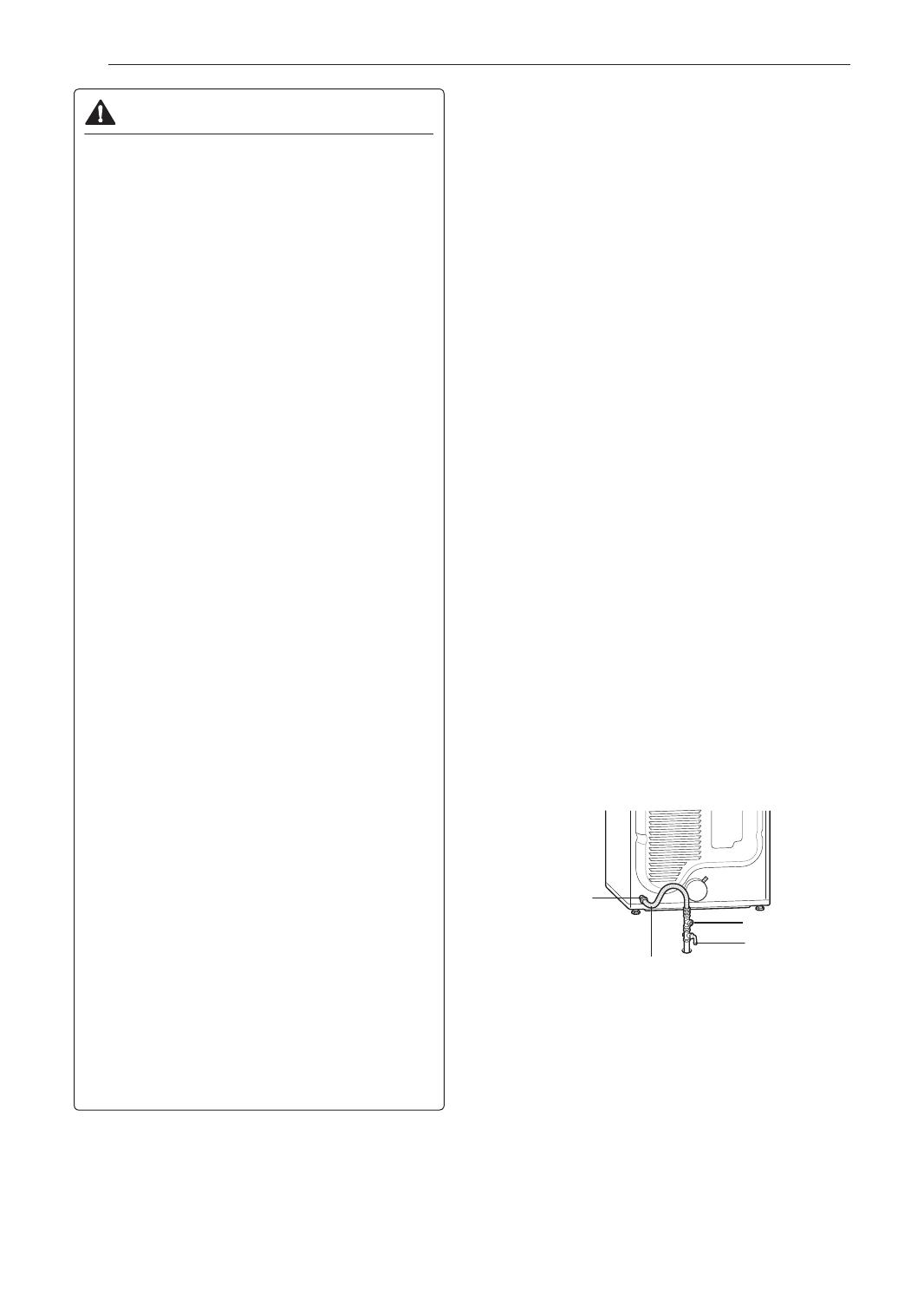
3/8" NPT gas
Connection
AGA/CSA-Certied
Stainless Steel Flexible
Connector
Gas Supply Shutoff
Valve
1/8" NPT Pipe Plug
High-Altitude Installations
The BTU rating of this dryer is AGA-certied for
elevations below 10,000 feet.
If your gas dryer is being installed at an elevation
above 10,000 feet, it must be derated by a qualied
technician or gas supplier.
  • Page 1 1
  • Page 2 2
  • Page 3 3
  • Page 4 4
  • Page 5 5
  • Page 6 6
  • Page 7 7
  • Page 8 8
  • Page 9 9
  • Page 10 10
  • Page 11 11
  • Page 12 12
  • Page 13 13
  • Page 14 14
  • Page 15 15
  • Page 16 16
  • Page 17 17
  • Page 18 18
  • Page 19 19
  • Page 20 20
  • Page 21 21
  • Page 22 22
  • Page 23 23
  • Page 24 24
  • Page 25 25
  • Page 26 26
  • Page 27 27
  • Page 28 28
  • Page 29 29
  • Page 30 30
  • Page 31 31
  • Page 32 32
  • Page 33 33
  • Page 34 34
  • Page 35 35
  • Page 36 36
  • Page 37 37
  • Page 38 38
  • Page 39 39
  • Page 40 40
  • Page 41 41
  • Page 42 42
  • Page 43 43
  • Page 44 44
  • Page 45 45
  • Page 46 46
  • Page 47 47
  • Page 48 48
  • Page 49 49
  • Page 50 50
  • Page 51 51
  • Page 52 52
  • Page 53 53
  • Page 54 54
  • Page 55 55
  • Page 56 56
  • Page 57 57
  • Page 58 58
  • Page 59 59
  • Page 60 60
  • Page 61 61
  • Page 62 62
  • Page 63 63
  • Page 64 64
  • Page 65 65
  • Page 66 66
  • Page 67 67
  • Page 68 68
  • Page 69 69
  • Page 70 70
  • Page 71 71
  • Page 72 72
  • Page 73 73
  • Page 74 74
  • Page 75 75
  • Page 76 76
  • Page 77 77
  • Page 78 78
  • Page 79 79
  • Page 80 80
  • Page 81 81
  • Page 82 82
  • Page 83 83
  • Page 84 84
  • Page 85 85
  • Page 86 86
  • Page 87 87
  • Page 88 88
  • Page 89 89
  • Page 90 90
  • Page 91 91
  • Page 92 92
  • Page 93 93
  • Page 94 94
  • Page 95 95
  • Page 96 96
  • Page 97 97
  • Page 98 98
  • Page 99 99
  • Page 100 100
  • Page 101 101
  • Page 102 102
  • Page 103 103
  • Page 104 104
  • Page 105 105
  • Page 106 106
  • Page 107 107
  • Page 108 108

LG DLG3171W Owner's manual

Category
Electric laundry dryers
Type
Owner's manual

Ask a question and I''ll find the answer in the document

Finding information in a document is now easier with AI

in other languages