GE GERAB46A Get installation instructions
- Type
- Get installation instructions
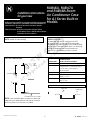
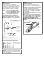
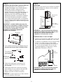
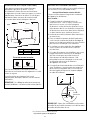
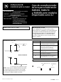
GE GERAB46A is a built-in air conditioner case designed for AJ Series models. It allows for proper distribution of conditioned air and can be installed in an outside wall to ensure efficient cooling. The case is modular in height and width, fitting 2 courses of concrete block, 6 courses of standard brick, or 5 courses of jumbo brick. It also fits approximately 2 stud spaces, making it suitable for various wall constructions. The case includes provisions for an optional external drain kit (RAD4A1) to carry condensate water away from the unit and the building.
GE GERAB46A is a built-in air conditioner case designed for AJ Series models. It allows for proper distribution of conditioned air and can be installed in an outside wall to ensure efficient cooling. The case is modular in height and width, fitting 2 courses of concrete block, 6 courses of standard brick, or 5 courses of jumbo brick. It also fits approximately 2 stud spaces, making it suitable for various wall constructions. The case includes provisions for an optional external drain kit (RAD4A1) to carry condensate water away from the unit and the building.


-
 1
1
-
 2
2
-
 3
3
-
 4
4
-
 5
5
-
 6
6
-
 7
7
-
 8
8
-
 9
9
-
 10
10
-
 11
11
-
 12
12


GE GERAB46A Get installation instructions
- Type
- Get installation instructions
GE GERAB46A is a built-in air conditioner case designed for AJ Series models. It allows for proper distribution of conditioned air and can be installed in an outside wall to ensure efficient cooling. The case is modular in height and width, fitting 2 courses of concrete block, 6 courses of standard brick, or 5 courses of jumbo brick. It also fits approximately 2 stud spaces, making it suitable for various wall constructions. The case includes provisions for an optional external drain kit (RAD4A1) to carry condensate water away from the unit and the building.
Ask a question and I''ll find the answer in the document
Finding information in a document is now easier with AI
in other languages
- français: GE GERAB46A
- español: GE GERAB46A
Related papers
Other documents
-
ReliaBilt 07-3043 User manual
-
 Frost King C21CP Installation guide
-
Ply Gem CLASSIC SH Installation guide
-
 DC America GONS83168 Installation guide
-
Friedrich CP10F10 Owner's manual
-
Daikin CTXG12QVJUS Installation guide
-
Mitsubishi Mr.Slim PKA-A.HA4 Installation guide
-
-
Mitsubishi Electric City Multi PKFY-P15 NGMU-E Installation guide
-

