Craftsman 919.167782 Owner's manual

Category
Air compressors
Type
Owner's manual

This manual is also suitable for

Owner's Manual
JCRRFTSMRN1
Permanently Lubricated
2-Stage
Twin V
Portable
AIR COMPRESSOR
Model No.
919.167782
Safety Guidelines
Assembly
Operation
Maintenance
Service and Adjustments
Troubleshooting
Repair Parts
CAUTION: Read the Safety Guidelines
and All Instructions Carefully Before
Operating.
Sears, Roebuck and Co., Hoffman Estates, IL 60179 U.S.A.
Visit our Craftsman website: www.eears.com/craftsman
D27299 Revl 3/25/03
hq:_:] ! :1EoJ_,_[_o] _hi _h I_-_
WARRANTY ............................................. 2
SPECIFICATION CHART .................................... 3
SAFETY GUIDELINES .................................... 3-8
GLOSSARY .............................................. 9
ACCESSORIES .......................................... 9
DUTY CYCLE ............................................ 9
ASSEMBLY ............................................. 1g
INSTALLATION ........................................ f1-12
OPERATION .......................................... f3-15
MAINTENANCE ....................................... f6-17
SERVICE AND ADJUSTMENTS ........................... f8-19
STORAGE .............................................. 20
TROUBLESHOOTING GUIDE ............................ 21-23
REPAIR PARTS ....................................... 24-27
ESPAI_IOL ............................................ 28-49
NOTES/NOTAS ....................................... 50-51
HOW TO ORDER REPAIR PARTS ..................... back cever
FULL ONE YEAR WARRANTY AIR COMPRESSOR
If this air cempresser fails due te a defect in material er workmanship within
one year from the date of purchase, RETURN IT TO THE NEAREST SEARS
REPAIR CENTER THROUGHOUT THE UNITED STATES AND SEARS WILL
REPAIR IT,FREE OF CHARGE. If purchased from Orchard Supply Hardware,
return to the nearest Orchard Store and Orchard will repair it, free of charge.
If this air compressor is used fer commercial er rental purposes, the warranty
will apply for ninety days from the date of purchase.
This warranty gives yeu specific legal rights and yeu may have other rights
which vary from state to state.
Sears, Roebuck and Co., Dept. 817WA, Hoffman Estates, II 60179
D27299 2* ENG
Model No.
Bore
Stroke
Voltage-Single Phase
Minimum Branch Circuit Requirement
Fuse Type
Air Tank Capacity - Gallons
Approximate Cut-in Pressure
Approximate Cut-out Pressure
919-167782
2.375"
High Pressure - .54"
Low Pressure - 1.45"
120
15 amps
Time Delay
25 ASME
145
175
[."Y:__1_ li'l_tl] Im]=1III#I=1.']-,Iml=1_11_Iil II[e_]_,[-._
This manual contains information that is important for you to know and understand. This information
relates to protecting YOUR SAFETY and PREVENTING EQUIPMENT PROBLEMS. To help you
recognize this inforrnation_ we use the symbols below. Please read the manual and pay attention to
these sections.
_lndicates an
imminently hazardous
situation which, if not avoided, will
result in death or serious injury.
_lndicates a potentially
hazardous situation
which, if not avoided, could result in
death or serious injury.
_l_'_lndicates a potentially
hazardous situation
which, if not avoided, _ result in
minor or moderate injuw.
_!_Used without the
safety alert symbol
indicates a potentially hazardous
situation which, if not avoided, may
result in property damaae.
Ih_l_o]-qnL+_+hd[-"_.,_l_S"d_[IP.[-:-]ljt,t[l_o,]njl[o_]P.[-.+
SAVE THESE INSTRUCTIONS
IMPROPER OPERATION OR MAINTENANCE OF THIS PRODUCT COULD RESULT IN
SERIOUS INJURY AND PROPERTY DAMAGE. READ AND UNDERSTAND ALL
WARNINGS AND OPERATING INSTRUCTIONS BEFORE USING THIS EQUIPMENT,
Some dust created by power sanding, sawing, grinding, drilling, and other
construction activities contains chemicals known (to the State of California) to
cause cancer, birth defects or other reproductive harm. Some example of these chemicals are:
lead from lead-based paints
crystalline silica from bricks and cement and other masonry products
arsenic and chromium from chemicalty4reated lumber
Your risk from these exposures varies, depending on how often you do this type of work. To reduce
your exposure to these chemicals: work in a well ventilated area, and work with approved safety
equipment, always wear MSHA/NIOSH approved, properly fitting face mask or respirator when using
such tools.
When using air tools, basic safety precautions should always be followed to reduce the risk of of
personal injury.
3* ENG D27299
I1_I_o];]lL"_ +Ill [,,'9'-'I_1_ i'dl I+F,,,_11_o _+]L_,[,,I
Save these instructions
improper operation or maintenance of this product could result in serious injury and
property damage. Read and understand all warnings and operation instructions before
using this equipment.
,I;1"1.,I;I n
WARNING: Risk of explosion or fire
What Could Happen
tt is normal for electrical contacts within
the motor and pressure switch to spark.
If electrical sparks from compressor
come into contact with flammable
vapors, they may ignite, causing fire or
explosion.
Restricting any of the compressor
ventilation openings will cause serious
overheating and could cause fire.
Unattended operation of this product
could result in personal injury or
property damage. To reduce the dsk of
fire, do not allow the compressor to
operate unattended.
How To Prevent It
Always operate the compressor in a well
ventilated area free of combustible
materials, gasoline, or solvent vapors.
If spraying flammable materials, locate
compressor at least 20 feet away from
spray area. An additional length of hose
may be required.
Store flammable matadals in a secure
location away from compressor.
Never place objects against or on top
of compressor. Operate compressor in
an open area at least 12 inches away
from any wall or obstruction that would
restrict the flow of fresh air to the
ventilation openings.
Operate compressor in a clean, dry well
ventilated area. DO not operate unit
indoors or in any confined area.
Always remain in attendance with the
product when it is operating
Always disconnect electrical power by
moving pressure switch lever to the off
position and drain tank daily or after
each use.
D27299 4* ENG
F_
WARNING: Risk of Bursting
Air Tank: The following conditions could lead to a weakening of the tank, and result
in a violent tank explosion and could cause property damage or serious injury.
2.
3.
What Could Happen
Failure to properly drain
condensed water from tank,
causing rust and thinning of the
steel tank.
How To Prevent It
Drain tank daily or after each use. If
tank develops a leak, replace it
immediately with a new tank or replace
the entire compressor.
Modifications or attempted repairs
to the tank,
Unauthorized modifications to the
unloader valve, safety valve, or any
other components which control
tank pressure.
Excessive vibration can weaken
the air tank and cause rupture or
explosion
Never drill into, weld, or make any
modifications to the tank or its
attachments.
4. The tank is designed to withstand specific
operating pressures. Never make
adjustments or parts substitutions to
alter the factory set operating
prossuros.
ATTACHMENTS & ACCESSORIES:
Exceeding the pressure rating of air
tools, spray guns, air operated
accessories, tires, and other inflatables
can cause them to explode or fly apart,
and could result in serious injury.
For essential control of air pressure, you
must install a pressure regulator and
pressure gauge to the air outlet (if not
equipped) of your compressor. Follow the
equipment manufacturers
recommendation and never exceed the
maximum allowable pressure rating of
attachments. Never use compressor to
inflate small low pressure objects such
as children's toys, footballs,
basketballs, etc.
,l:_'!'J l l=
WARNING: Risk from Flying Objects
WHAT CAN HAPPEN HOWTO PREVENT IT
The compressed air stream can cause
soft tissue damage to exposed skin and
can propel dirt, chips, loose particles,
and small objects at high speed,
resulting in property damage or personal
injury.
Always wear ANSI Z87.1 approved safety
glasses with side shields when using the
compressor,
Never point any nozzle or sprayer
toward any part of the body or at other
people or animals.
Always turn the compressor off and
bleed pressure from the air hose and tank
before attempting maintenance, attaching
tools or accessories.
5* ENG D27299
WARNING: Risk of Electrical Shock
WHAT CAN HAPPEN
Your air compressor is powered by
electricity. Like any other electrically
powered device, If it is not used properly
it may cause electric shock.
Repairs attempted by unqualified
personnel can result in serious injury or
death by electrocution,
Electrical Grounding: Failure to provide
adequate grounding to this product
could result in serious injury or death
from electrocution.
See grounding instructions.
HOW TO PREVENT IT
Never operate the compressor outdoors
when it is raining or in wet conditions.
Never operate compressor with
protective covers removed or damaged
Any electrical wiring or repairs required
on this product should be performed by
authorized service center personnel in
accordance with national and local
elect rical codes.
Make certain that the electrical circuit
to which the compressor is connected
provides proper electrical grounding,
correct voltage and adequate fuse
protection,
,I;1"1'.I;1=
WARNING: Risk to Breathing
WHAT CAN HAPPEN
The compressed air directly from your
compressor is not safe for breathing
The air stream may contain carbon
monoxide, toxic vapors, or solid
particles from the tank. Breathing these
contaminants can cause serious injury
or death.
Sprayed materials such as paint, paint
solvents, paint remover, insecticides,
weed killers, may contain harmful vapors
and poisons.
HOW TO PREVENT IT
Air obtained directly from the compressor
should never be used to supply air for
human consumption, In order to use air
produced by this compressor for
breathing, suitable filters and in-line
safety equipment must be properly
installed. In-line filters and safety
equipment used in conjunction with the
compressor must be capable of treating
air to all applicable local and federal
codes prior to human consumption.
Work in an area with good cross
ventilation. Read and follow the safety
instructions provided on the label or
safety data sheets for the materials you
are spraying, Use a NtOSH/MSHA
approved respirator designed for use
with your specific application.
D27299 6* ENG
WARNING: RISK OF BURNS
WHAT CAN HAPPEN
Touching exposed metal such as the
compressor head or outlet tubes, can
result in serious burns,
HOW TO PREVENT IT
Never touch any exposed metal parts
on compressor during or immediately
after operation. Compressor will remain
hot for several minutes after operation.
Do not reach around protective shrouds
or attempt maintenance until unit has
been allowed to cool.
,l;_'l'J l l=
WARNING: RISK FROM MOVING PARTS
WHAT CAN HAPPEN
Moving parts such as the pulley, flywheel,
and bait can cause serious injury if they
corn into contact with you or your
clothing.
Attempting to operate compressor with
damaged or missing parts or attempting
to repair compressor with protective
shrouds removed can expose you to
moving parts and can result in serious
injury.
HOW TO PREVENT IT
Never operate the compressor with
guards or covers which are damaged or
removed.
Any repairs required on this product
should be performed by authorized
service center personnel.
,l;_'l'J l l=
WARNING: RISK OF FALLING
WHAT CAN HAPPEN
A portable compressor can fall from a table,
workbench or roof causing damage to the
compressor and could result in serious
injury or death to the operator.
HOW TO PREVENT IT
Always operate compressor in a stable secure
position to prevent accidental movement of the
unit. Never operate compressor on a roof or
other elevated position. Use additional air
hose to reach high locations.
,l;_'l'J l l=
WARNING: RISK OF SERIOUS INJURY OR PROPERTY
DAMAGE WHEN TRANSPORTING COMPRESSOR
(Fire, Inhalation, Damage to Vehicle Surfaces)
WHAT CAN HAPPEN
Oil can leak or spill and could result in
fire or breathing hazard; serious injury or
death can result. Oil leaks will damage
carpet, paint or other surfaces in vehicles
or trailers.
HOW TO PREVENT IT
Always place compressor on a
protective mat when transporting to
protect against damage to vehicle from
leaks. Remove compressor from vehicle
immediately upon arrival at your
destination.
ENG D27299
WARNING: RISK OF UNSAFE OPERATION
WHAT CAN HAPPEN
Unsafe operation of your air compressor
could lead to serious injury or death to
you or others.
HOW TO PREVENT IT
Review and understand all instructions
and warnings in this manual.
Become familiar with the operation and
controls of the air compressor.
Keep operating area clear of all persons,
3ets, and obstacles.
Keep children away from the air
compressor st all times,
Do not operate the product when
fatigued or under the influence of
alcohol or drugs. Stay alert at all times.
Never defeat the ssfety features of this
_roduct.
Equip ares of operation with a fire
extinguisher.
DO not operate machine with missing,
broken, or unauthorized parts.
D27299 8* ENG
Become familiar with these terms
before operating the unit.
CFM: Cubic feet per minute.
SCFM: Standard cubic feet per
minute; a unit of measure of air
delivery.
PSIG: Pounds per square inch
gauge; a unit of measure of pressure.
Code Certification: Products that
bear one or more of the following
marks: UL, CUL, ETL, CETL, have
been evaluated by OSHA certified
independent safety laboratories and
meet the applicable Underwriters
Laboratories Standards for Safety.
Cut-In Pressure: While the motor is
off, air tank pressure drops as you
continue to use your accessory.
When the tank pressure drops to a
certain low level the motor will restart
automatically. The low pressure at
which the motor automatically
restarts is called "cut-in" pressure.
Cut-Out Pressure: When an air
compressor is turned on and begins
to run, air pressure in the air tank
begins to build. It builds to a certain
high pressure before the motor
automatically shuts off, protecting
your air tank from pressure higher
than its capacity. The high pressure
at which the motor shuts off is called
"cut-out" pressure.
Branch Circuit: Circuit carrying
electricity from electrical panel to
outlet.
This unit is capable of powering the following Accessories. The accessories are
available through the current Power and Hand Tool Catalog or full-line Sears
stores.
Accessories
In Line Filter
TireAir Chuck
Quick Connector Sets (various
sizes)
Air Pressure Regulators
Oil Fog Lubricators
Air Hose: 1/4", 3/8" or 1/2" I.D. in
various lengths
Refer to the selection chart located
on the unit to select the tools this unit
is capable of powering.
_uJunk'd[e,,_ al=1
Air compressors should be operated
on not more than a 50% duty cycle.
This means an air compressor that
pumps air more than 50% of one
hour is considered misuse, because
the air compressor is undersized for
the required air demand. Maximum
compressor pumping time per hour is
30 minutes.
9-ENG D27299
Contents of Carton
1 - Air Compressor
2- Wheels
2 - Shoulder Bolts, 3/8-16
2 - Hex Nuts, 3/8-16
2 - Rubber Bumpers
2 - Screws, 1/4-20 x .75"
Tools Required for Assembly
1 - 9/16" socket or open end wrench
1 - 1/2" socket or open end wrench
Unpacking
1. Remove all packaging leaving
the air compressor on the pallet.
2. Remove and discard the (4)
screws holding the air
compressor to the pallet.
It may be
necessary to brace
or support one side of the air
compressor when removing the
pallet because the air compressor
will have a tendency to tip.
3. Carefully remove the air
compressor from the pallet.
Assemble Wheels
It will be necessary
to brace or support
one side of the air compressor
when installing the wheels because
the compressor will have a
tendency to tip.
1. Attach wheels with shoulder
bolts and nuts as shown.
[_ _ _ Rubber
Nut _
whee,Z /
Shoulder
Bolt
2. Tighten securely. NOTE: The air
compressor will sit level if the
wheels are properly installed.
I_'_'j_ The wheels and
handle do not
provide adequate clearance,
stability or support for pulling the
unit up and down stairs or steps.
The unit must be lifted, or pushed
up a ramp.
Assemble Rubber Feet
1. Attach rubber feet with the
screws provided as shown in
previous figure.
2. Tighten securely.
D27299 10-ENG
I I_[-.'_1Iv;_II It;'1II[o_]l
HOW TO SET UP YOUR
UNIT
Location of the Air Compressor
Locate the air compressor in a clean,
dry and well ventilated area. The air
compressor should be located at
least 12" away from the wall or other
obstructions that will interfere with
the flow of air. The air compressor
pump and shroud are designed to
allow for proper cooling. The
ventilation openings on the
compressor are necessary to
maintain proper operating
temperature. Do not place rags or
other containers on or near these
openings.The air filter must be kept
clear of obstructions which could
reduce air flow to the air compressor.
GROUNDING INSTRUCTIONS
RISK OF
ELECTRICAL
SHOCK. In the event of a short
circuit, grounding reduces the risk
of shock by providing an escape
wire for the electric current. This
air compressor must be properly
grounded.
The portable air compressor is
equipped with a cord having a
grounding wire with an appropriate
grounding plug (see following
illustrations). The plug must be used
with an outlet that has been installed
and grounded in accordance with all
local codes and ordinances.
1. The cord set and plug with this
unit contains a grounding pin.
This plug MUST be used with a
grounded outlet.
IMPORTANT: The outlet being used
must be installed and grounded in
accordance with all local codes and
ordinances.
2.
Make sure the outlet being used
has the same configuration as
the grounded plug. DO NOT
USE AN ADAPTER. See
illustration.
1_lu_j _Grounded
_ l_ Outlets
Grou_d!ing Pin
3. Inspect the plug and cord before
each use. Do not use if there are
signs of damage.
4. If these grounding instructions
are not completely understood,
or if in doubt as to whether the
compressor is properly
grounded, have the installation
checked by a qualified
electrician.
CA.
RESULT IN ELECTRICAL SHOCK.
Do not modify the plug provided. If
it does not fit the available outlet, a
correct outlet should be installed
by a qualified electrician.
Repairs to the cord set or plug
MUST be made by a qualified
electrician.
11_ ENG D27299
Extension Cords
Using extension cords is not
recommended. The use of extension
cords will cause voltage to drop
resulting in power loss to the motor
and overheating.
Attach extra air hoses at the air outlet
instead of using extension cords.
If an extension cord must be used,
be sure it is:
a 3-wire extension cord that has
a 3-blade grounding plug, and a
3-slot receptacle that will accept
the plug on the product
in good condition
no longer than 50 feet
12 gauge (AWG) or larger. (Wire
size increases as gauge number
decreases. 10 AWG and 8 AWG
may also be used. DO NOT USE
14 OR 16 AWG.)
Voltage and Circuit Protection
Refer to the Parts Manual for the
voltage and minimum branch circuit
requirements.
Certain air compressors can be
operated on a 15 amp circuit if the
following conditions are met.
1. Voltage supply through branch
circuit is 15 amps.
2. Circuit is not used to supply any
other electrical needs (lights,
appliances, etc.).
3. Extension cords comply with
specifications.
4.
Circuit is equipped with a 15
amp circuit breaker or 15 amp
time delay fuse. NOTE: If
compressor is connected to a
circuit protected by fuses, use
only time delay fuses. Time delay
fuses should be marked "D" in
Canada and "T" in the US.
If any of the above conditions cannot
be met, or if operation of the
compressor repeatedly causes
interruption of the power, it may be
necessary to operate it from a 20
amp circuit. It is not necessary to
change the cord set.
D27299 12-ENG
Know Your Air Compressor
READ THIS OWNER'S MANUAL AND SAFETY RULES BEFORE OPERATING
YOUR UNIT. Compare the illustrations with your unit to familiarize yourself with
the location of various controls and adjustments. Save this manual for future
reference.
Outlet
Pressure i
Gauge
Safety Valve
Description of Operation
Become familiar with these controls
before operating the unit.
On/Auto/Off Switch: Turn this switch
ON to provide automatic power to
the pressure switch and OFF to
remove power at the end of each
use.
Pressure Switch: The pressure
switch automatically starts the motor
when the air tank pressure drops
below the factory set "cut-in"
pressure. It stops the motor when the
air tank pressure reaches the factory
set "cut-out" pressure.
Safety Valve: If the pressure switch
does not shut off the air compressor
at its "cut-out" pressure setting, the
safety valve will protect against high
pressure by "popping out" at its
factory set pressure (slightly higher
than the pressure switch "cut-out"
setting).
Outlet Pressure Gauge: The outlet
pressure gauge indicates the air
pressure available at the outlet side
of the regulator. This pressure is
controlled by the regulator and is
always less than or equal to the tank
pressure.
13_ ENG
Tank Pressure Gauge: The tank
pressure gauge indicates the reserve
air pressure in the tank.
Regulator: Controls the air pressure
shown on the outlet pressure gauge.
Pull the knob out and turn clockwise
to increase pressure and
counterclockwise to decrease
pressure. When the desired pressure
is reached push knob in to lock in
place.
Drain Valve: The drain valve is
located at the base of the air tank
and is used to drain condensation at
the end of each use.
Cooling System (not shown): This
compressor contains an advanced
design cooling system. At the heart
of this cooling system is an
engineered fan. It is perfectly normal
for this fan to blow air through the
vent holes in large amounts. You
know that the cooling system is
working when air is being expelled.
D27299
Air Compressor Pump (not shown):
Compresses air into the air tank.
Working air is not available until the
compressor has raised the air tank
pressure above that required at the
air outlet.
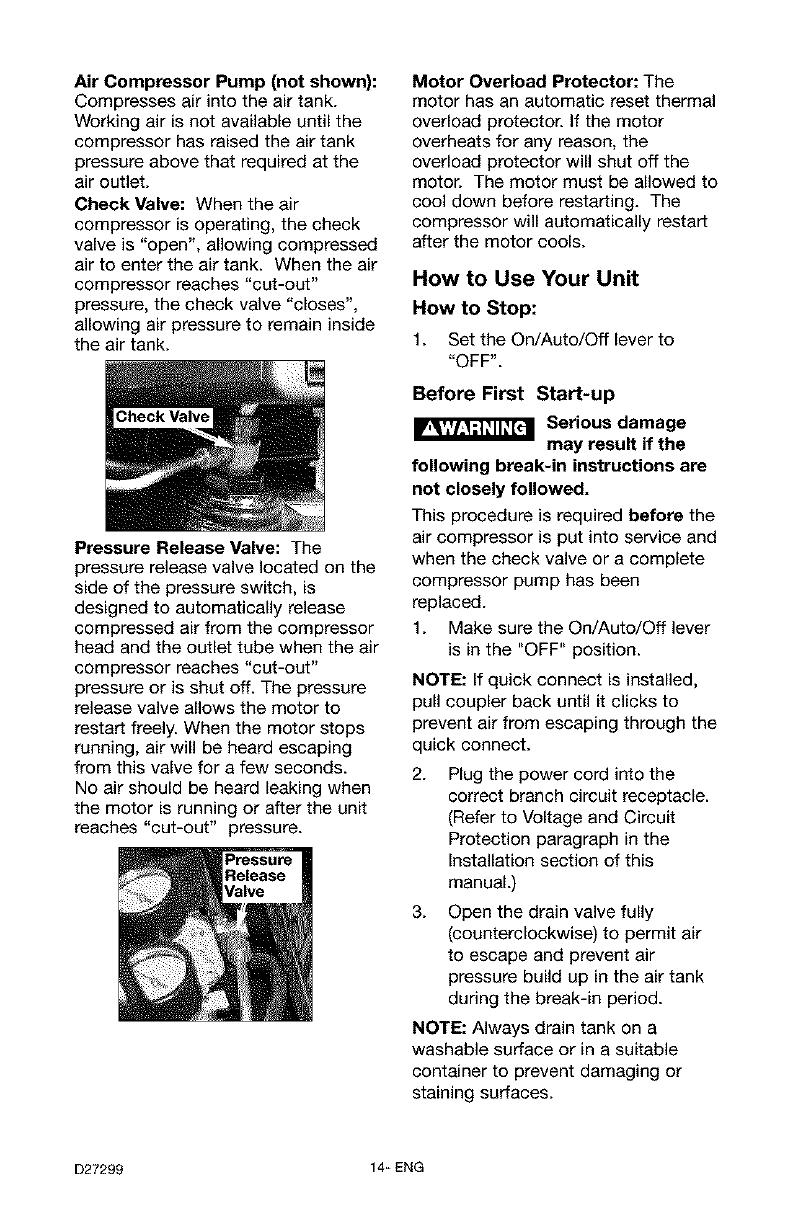
Check Valve: When the air
compressor is operating, the check
valve is "open", allowing compressed
air to enter the air tank. When the air
compressor reaches "cut-out"
pressure, the check valve "closes",
allowing air pressure to remain inside
the air tank.
Pressure Release Valve: The
pressure release valve located on the
side of the pressure switch, is
designed to automatically release
compressed air from the compressor
head and the outlet tube when the air
compressor reaches "cut-out"
pressure or is shut off. The pressure
release valve allows the motor to
restart freely. When the motor stops
running, air will be heard escaping
from this valve for a few seconds.
No air should be heard leaking when
the motor is running or after the unit
reaches "cut-out" pressure.
Motor Overload Protector: The
motor has an automatic reset thermal
overload protector. If the motor
overheats for any reason, the
overload protector will shut off the
motor. The motor must be allowed to
cool down before restarting. The
compressor will automatically restart
after the motor cools.
How to Use Your Unit
How to Stop:
1. Set the On/Auto/Off leverto
"OFF".
Before First Start-up
Serious damage
may result if the
following break-in instructions are
not closely followed.
This procedure is required before the
air compressor is put into service and
when the check valve or a complete
compressor pump has been
replaced.
1. Make sure the On/Auto/Off lever
is in the "OFF" position.
NOTE: If quick connect is installed,
pull coupler back until it clicks to
prevent air from escaping through the
quick connect.
2. Plug the power cord into the
correct branch circuit receptacle.
(Refer to Voltage and Circuit
Protection paragraph in the
Installation section of this
manual.)
3. Open the drain valve fully
(counterclockwise) to permit air
to escape and prevent air
pressure build up in the air tank
during the break-in period.
NOTE: Always drain tank on a
washable surface or in a suitable
container to prevent damaging or
staining surfaces.
D27299 14_ENG
4. Move the On/Auto/Off lever to
"ON/AUTO" position. The
compressor will start.
5. Run the compressor for 15
minutes. Make sure the drain
valve is open and there is
minimal air pressure build-up in
tank.
6. After 15 minutes, close the drain
valve (clockwise). The air receiver
will fill to "cut-out" pressure and
the motor will stop.
The compressor is now ready for use.
Before Each Start-Up:
1. Place On/Auto/Off lever to
"OFF".
2. Pull regulator knob out, turn
counterclockwise until it stops.
Push knob in to lock in place.
3. Attach hose and accessories.
NOTE: The hose or accessory
will require a quick connect plug
if the air outlet is equipped with a
quick connect.
TOO much air
pressure causes a
hazardous risk of bursting, Check
the manufacturer's maximum
pressure rating for air tools and
accessories. The regulator outlet
pressure must never exceed the
maximum pressure rating.
How to Start:
1. Turn the On/Auto/Off lever to
"AUTO" and allow tank pressure
to build. Motor will stop when
tank pressure reaches "cut-out"
pressure.
2. Pull the regulator knob out and
turn clockwise to increase
pressure. When the desired
pressure is reached push knob in
to lock in place. The compressor
is ready for use.
NOTE: Always operate the air
compressor in well-ventilated areas
free of gasoline or other combustible
vapors. If the compressor is being
used to operate a sprayer DO NOT
place near the spray area.
15_ENG D27299
Customer Responsibilities
Before Daily ol
after Every Every
aach each 40 100 Yearly
use use hours _ours
Check Safety Valve
Drain Tank
Air Filter •_
Air compressor pump intake
and exhaust valves
1- more frequent in dusty or humid conditions
Unit cycles
automatically when
power is on. When performing
maintenance, you may be exposed
to voltage sources, compressed
air, or moving parts. Personal
injuries can occur. Before
performing any maintenance or
repair, disconnect power source
from the compressor and bleed off
all air pressure.
To ensure efficient operation and
longer life of the air compressor
outfit, a routine maintenance
schedule should be prepared and
followed. The following routine
maintenance schedule is geared to
an outfit in a normal working
environment operating on a daily
basis. If necessary, the schedule
should be modified to suit the
conditions under which your
compressor is used. The
modifications will depend upon the
hours of operation and the working
environment. Compressor outfits in
an extremely dirty and/or hostile
environment will require a greater
frequency of all maintenance checks.
NOTE: See "Operation" section for
the location of controls.
D27299
To Check Safety Valve
if the safety valve
does not work
properly, over-pressurization may
occur, causing air tank rupture or
an explosion,
1. Before starting compressor, pull
the ring on the safety valve to
make sure that the safety valve
operates freely. If the valve is
stuck or does not operate
smoothly, it must be replaced
with the same type of valve.
To Drain Tank
1. Set the On/Auto/Off lever to
"OFF".
2. Pull the regulator knob out and
turn counter-clockwise to set the
outlet pressure to zero.
3. Remove the air tool or
accessory.
4.
Pull ring on safety valve allowing
air to bleed from the tank until
tank pressure is approximately
20 psi. Release safety valve ring.
5. Drain water from air tank by
opening drain valve (counter-
clockwise) on bottom of tank.
Water will
condense in the air
tank. If not drained, water will
corrode and weaken the air tank
causing a risk of air tank rupture.
16_ ENG
6. After the water has been drained,
close the drain valve (clockwise).
The air compressor can now be
stored.
NOTE: If drain valve is plugged,
release all air pressure. The valve
can then be removed, cleaned, the
reinstalled.
Air Filter Inspection and
Replacement
Hot surfaces. Risk
of burn. Compres-
sor heads are exposed when filter
cover is removed. Allow
compressor to cool prior to
servicing.
A dirty air filter will not allow the
compressor to operate at full
capacity. Keep the air filter clean at
all times.
1. Remove the air filter cover.
2. Remove the air filter and make
sure it is clean.
IMPORTANT: Do not operate the
compressor with the air filter
removed.
3. If dirty, rinse air filter with warm
water and squeeze dry.
4. Replace air filter and air filter
cover.
NOTE: If the air filter is extremely
dirty it will need to be replaced. Refer
to the "Repair Parts" for the correct
part number.
Air Compressor Pump Intake
and Exhaust Valves
Once a year have a Trained Service
Technician check the air compressor
pump intake and exhaust valves.
MoOr
The motor has an automatic reset
thermal overload protector, if the
motor overheats for any reason, the
overload protector will shut off the
motor. The motor must be allowed to
cool down before restarting. The
compressor will automatically restart
after the motor cools.
if the overload protector shuts the
motor off frequently, check for a
possible voltage problem. Low
voltage can also be suspected when:
1. The motor does not get up to full
power or speed.
2. Fuses blow out when starting
the motor; lights dim and remain
dim when motor is started and is
running.
17_ ENG D27299
_'_jl_ Unit cycles
automatically when
power is on. When doing
Maintenance, you may be exposed
to voltage sources, compressed air
or moving parts. Personal injuries
can occur. Before performing any
Maintenance or repair, unplug the
compressor and bleed off all air
pressure.
ALL MAINTENANCE AND REPAIR
OPERATIONS NOT LISTED MUST
BE PERFORMED BY A TRAINED
SERVICE TECHNICIAN.
TO Replace or Clean Check
Valve
1. Release all air pressure from air
tank. See "To Drain Tank" in the
Maintenance section.
2. Unplug outfit.
3. Using a phillips screwdriver,
remove the air filter cover.
Outlet Tube
7.
8.
Unscrew the check valve (turn
counterclockwise) using a 7/8"
open end wrench. Note the
orientation for reassembly.
Using a screwdriver, carefully
push the valve disc up and
down. NOTE: The valve disc
should move freely up and down
on a spring which holds the valve
disc in the closed position; if not
the check valve needs to be
cleaned or replaced.
Screwdriver
position
nothing is
visible,
4. Remove the rear shrouds using
T-20 torx wrench.
In closed position
disc is visible.
5. Using an adjustable wrench,
loosen outlet tube nut at air tank.
Carefully move outlet tube away
from check valve.
6. Using an adjustable wrench
loosen pressure relief tube nut at
air tank. Carefully move pressure
relief tube away from check
valve.
D27299
9. Clean or replace the check valve.
A solvent, such as paint or
varnish remover can be used to
clean the check valve.
10. Apply sealant to the check valve
threads. Reinstall the check valve
(turn clockwise).
11. Replace the pressure release
tube. Tighten nut.
12. Replace the outlet tube and
tighten nut.
13. Replacethe shroud and air filter.
14. Perform the Break-in Procedure.
See "Break-in Procedure" in the
Operation section.
18_ENG
To Replace Regulator
1. Release all air pressure from air
tank. See "To Drain Tank" in the
Maintenance section.
2. Unplug compressor.
3. Remove the outlet pressure
gauge and quick connect (if
equipped) from the regulator.
4. Remove the regulator.
6. Assemble the regulator and
orient as shown.
NOTE: Arrow indicates flow of air.
Make sure it is pointing in the
direction of air flow.
5.
Apply pipe sealant tape to the
nipple.
7.
8.
Reapply pipe sealant to outlet
pressure gauge and quick
connect.
Reassemble outlet pressure
gauge and quick connect. Orient
outlet pressure gauge to read
correctly. Tighten quick connect
with wrench.
19_ ENG D27299
Before you store the air compressor,
make sure you do the following:
1. Review the "Maintenance"
section on the preceding pages
and perform scheduled
maintenance as necessary.
2. Set the On/Auto/Off lever to
"OFF".
3. Turn the regulator
counterclockwise and set the
outlet pressure to zero.
4. Removethe air tool or
accessory.
5. Pull ring on safety valve allowing
air to bleed from the tank until
tank pressure is approximately
20 psi. Release safety valve ring.
6. Drain water from air tank by
opening drain valve on bottom of
tank.
Water will
condense in the air
tank. If not drained, water will
corrode and weaken the air tank
causing a risk of air tank rupture.
7. After the water has been drained,
close the drain or drain valve.
NOTE: If drain valve is plugged,
release all air pressure. The valve
can then be removed, cleaned, then
reinstalled.
8. To protect the electrical cord
from damage wind electrical cord
loosely around the compressor
handle.
9. Wind air hose around hose wrap
and secure in place.
Store the air compressor in a clean
and dry location.
D27299 20-ENG
  • Page 1 1
  • Page 2 2
  • Page 3 3
  • Page 4 4
  • Page 5 5
  • Page 6 6
  • Page 7 7
  • Page 8 8
  • Page 9 9
  • Page 10 10
  • Page 11 11
  • Page 12 12
  • Page 13 13
  • Page 14 14
  • Page 15 15
  • Page 16 16
  • Page 17 17
  • Page 18 18
  • Page 19 19
  • Page 20 20
  • Page 21 21
  • Page 22 22
  • Page 23 23
  • Page 24 24
  • Page 25 25
  • Page 26 26
  • Page 27 27
  • Page 28 28
  • Page 29 29
  • Page 30 30
  • Page 31 31
  • Page 32 32
  • Page 33 33
  • Page 34 34
  • Page 35 35
  • Page 36 36
  • Page 37 37
  • Page 38 38
  • Page 39 39
  • Page 40 40
  • Page 41 41
  • Page 42 42
  • Page 43 43
  • Page 44 44
  • Page 45 45
  • Page 46 46
  • Page 47 47
  • Page 48 48
  • Page 49 49
  • Page 50 50
  • Page 51 51
  • Page 52 52

Craftsman 919.167782 Owner's manual

Category
Air compressors
Type
Owner's manual
This manual is also suitable for

Ask a question and I''ll find the answer in the document

Finding information in a document is now easier with AI

in other languages