Bushnell Nov-00 User manual
- Category
- Infrared bulbs
- Type
- User manual
This manual is also suitable for

Models: 11-9600/11-9800
LIT. #: 98-0534/0
2-05
Model: 11-9900
Trail Scout 6LIM.indd 1 1/25/05 4:25:45 PM

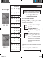
CONTENTS
English ............
2
Français .........
19
Español ......... 37
Deutsch .........
55
Italiano ..........
73
Português ......
91
1
Trail Scout 6LIM.indd 2-3 1/25/05 4:25:45 PM

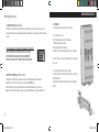
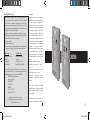
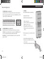
119600—Digital Trail Scout VGA
Great images and scouting technology at a great value. This camera will sense deer and other
game as far out as 60 feet with its passive infrared sensor. Low-battery indicator lights when
battery life drops below 25%. Motion LED lights when activity is detected by the sensor in
regular imaging mode and during setup mode for aiming. Weatherproof. Comes complete
with aircraft aluminum security cable, padlock, and tree bracket. Textured “bark-like” surface
for maximum concealment.
119800—Digital Trail Scout 2.1MP
All the features of the Trail Scout VGA, but featuring superior image resolution and increased
range. This camera senses deer as far out as 90 feet with its passive infrared sensor.
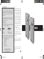
119900—Digital Trail Scout 2.1MP with Night Vision
With all the features of the 2.1MP Trail Scout plus Night Vision and laser aiming , this is the top
of the line digital trail camera. This is the only game camera on the market to combine both
incandescent camera flash and digital night vision technology. Choose your setting for regular
camera flash or stealth-like LED flash. LED flash enables you to discretely image game in the
night without a visible flash. There is no need to worry about your flash giving away your posi
-
tion in popular, busy hunting areas. This camera comes complete with laser aiming device for
easy set up in the woods.
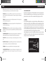
DIGITAL TRAIL SCOUT MODELS
Congratulations on your purchase of the Bushnell
®
Digital Trail Scout
™
Camera!
This trail camera is designed to record the activity of wildlife game in the outdoors
with it’s still image and movie modes and weatherproof, rugged construction.
This instruction manual is designed to maximize your understanding of how the
camera operates.
Bushnell Digital Trail Scout Features (All Models)
One of the most revolutionary advances in scouting technology to date, the Bushnell Digital Trail
Scout delivers. Boasting one of the most user friendly interfaces in the industry, this trail camera
has a positive toggle switch system that instantly tells you what your camera setting are—without
fumbling with a confusing software interface! The built-in security system has four levels of security.
Every Trail Scout comes complete with padlock, cable lock, tree bracket for screw attachment, and
software password that locks out would-be thieves. The high resolution digital camera delivers crisp
views of game in your area and stamps each image with date, time, and name. Along with regular
image mode, there is a movie mode for 15 second movie clips. All images, movies and event are
recorded onto an SD card (a 32MB card is included) for convenient transfer to your home computer.
The camera will function during day, night, or all 24 hours and sense game out to 90 feet. The over
-
sized incandescent flash will reach out to 30 feet for nighttime images. Image delay settings include
30 seconds, 1 minute and 2 minutes. The innovative backlit LCD makes set up a breeze in the field.
The Trail Scout is weatherproof and rugged.
2
3
Trail Scout 6LIM.indd 4-5 1/25/05 4:25:45 PM

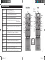
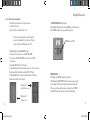
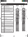
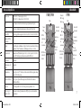
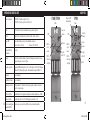
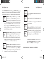
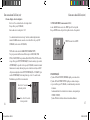
119600/119800
119900
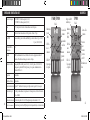
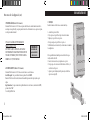
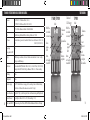
Parts
Guide
Flash
Camera
Lens
PIR
Motion
LED
Low
Battery
LED
SD Card
Slot
Keylock
Flash
PIR
Camera
Lens
Motion
LED
Low
Battery
LED
Laser
Pointer
Infrared
LED Array
SD Card
Slot
Keylock
DIGITAL TRAIL SCOUT SPECIFICATIONS
Image Sensor 1/4” CMOS, 0.35 million pixels (119600)
1/2” CMOS, 2.1 million pixels (119800/119900)
Lens F/3.5, effective focal length 42mm. Sight range: 45 degrees
Flash High power electronic Incandescent Flash. Range: 30 ft.
PIR Sensor Low noise, high sensitivity passive infrared sensor. Range: 60 ft. (119600)
90 ft. (119800/119900)
Motion LED Indicator Yes
Display Backlit LCD, 2 rows x 8 characters. Auto-off: 3 min. 2-digit event and image
display.
File Format Still image JPG 640x480 pixels (119600), 1600x1200 pixels (119800/119900). Movie
images AVI 320x240 pixel per frame. DCF ver. 1.0 file management.
Exposure Auto
White Balance Auto
Power Supply 4 x “D” cell batteries. Low battery indicator at 25% remaining power.
Battery Life Approximately 30 days (dependant on temperature, camera activity and flash us-
age)
User Password Yes, available range: 0000 to 9999 (Default setting = 0000)
Other (
) Remote control, Laser pointer, LED for night vision infrared imaging
4
5
Trail Scout 6LIM.indd 6-7 1/25/05 4:25:47 PM

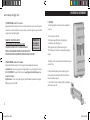
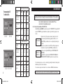
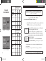
SETUP GUIDE
1. K1 - Mode Switch (OFF / SETUP/ ON) :
a) Power ON (UP position): Set K1 to ON position, The LCD display will show “BUSHNELL”
for about 2 seconds, and then will prompt to input your password.
Press Up or Down key to select the first password digit of 0-9.
Note: the factory programmed default password is 0000.
Press ENTER to confirm, the cursor will move to the next digit to the right.
Repeat the process using UP, Down and Enter keys to enter your four digit
password. Press ENTER to confirm, if the password is correct the LCD will
display EVENT/IMAGE.
The LCD will rotate through the DATE\TIME\EVENT&IMAGE displays
when pressing the Up and Down keys.
PASSWORD
0_ _ _
EVENT nn
IMAGE nn
If the password entered was correct, or if the password was never previously programmed, the unit
will be enabled after a 5 minute delay.
If the password is entered incorrectly 3 times the unit will be turned OFF automatically.
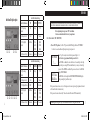
Before beginning the setup, insert 4 “D” size alkaline
batteries as indicated inside the battery compartment.
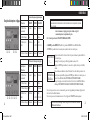
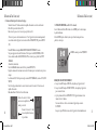
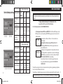
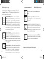
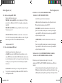
Switch and Setup Description
Switch Position/Setting
Switch #/Function UP CENTER DOWN
K1 (Operating
Mode)
On Setup Off
K2 (Image Mode) Still
- Movie
K3 (Day/Night
Mode)
24 Hour Day
(6AM-
6PM)
Night
(6PM-
6AM)
K4 (Camera Delay) 2 minutes 1 minute 30 seconds
Switch Position/Setting
Switch #/Function UP CENTER DOWN
K1 (Operating
Mode)
On Setup Off
K2 (Image Mode) Still
- Movie
K3 (Lighting Mode) LED - Incand.
K4 (Day/Night
Mode)
24 Hour Day
(6AM-
6PM)
Night
(6PM-
6AM)
K5 (Camera Delay) 2 minutes 1 minute 30 seconds
K1 K2 K3 K4
K1 K2 K3 K4 K5
Up/Down/Enter
Up/Down/Enter
6
7
Trail Scout 6LIM.indd 8-9 1/25/05 4:25:47 PM

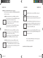
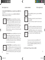
When the LCD shows [Password Set], press the ENTER key to set the password.
The LCD will show [Password Yes]. To change the password, press Enter.
If you do not want to set a password, you can press the Up or Down key to select NO.
If you selected YES, the LCD shows [New Pswd]. Press the Up or Down key to select
the first password digit of 0-9. Press ENTER to confirm, the cursor will move to the
next digit to the right. Repeat the process using UP, Down and Enter keys to enter
your four digit password. Press ENTER to confirm.
If you do not want to set a password when the LCD shows (PW YES) , you can press
the U/D button to select No, After pressing the ENTER, the LCD display shows (PW
NO), and no password will be set.
(4) SET PASSWORD:
New Pswd
0 0 0 0
Password
Set
Password
None
Password
Yes
When you are finished with SETUP, change K1 to the ON (UP) position and the
unit will be operating after a 5 minute delay.
c) Power OFF: Set K1 to “Off”, the Trail Scout will be OFF.
b) SETUP Mode [move switch K1 from UP (ON) position to center position]:
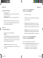
Press Up or Down buttons to scroll through choices of DATE, TIME, NAME and PASSWORD
to modify or set these functions.
(1) SET DATE: When the LCD shows the date, press the ENTER key to modify the date.
Press Up or Down button to select 1-12 then press the ENTER button to confirm
the two digit month. The cursor will then move to the day.
Press Up or Down button to select 1-31 then press ENTER to confirm the two
digit day. Then the cursor will move to the year.
Press Up or Down button to select 0-99,then press ENTER to confirm the two
digit year. From Set Date, press the Down button to set the time.
(2) SET TIME: When the LCD shows the time, press the ENTER key to modify the time.
Press Up or Down button to select 1-12, then press ENTER to confirm the two
digit hour. Then the cursor will move to the minute.
Press Up or Down button to select 0-59, then press ENTER to confirm the two
digit minute. From SET TIME, press the Down button to set the name.
(3) SET NAME: When the LCD shows current name, press ENTER key to modify the
name display. Press Up or Down button to select one character from “A” to “Z”,
“0” to “9”, ”_” , then Press ENTER to confirm, the cursor will move to next character.
There are 2 lines of 8 characters each for your use. From Set Name, press the Down
button to change the password.
Set Date
09/18/04
Set Time
06: 30 PM
MY NAME
555_1234
8
9
Trail Scout 6LIM.indd 10-11 1/25/05 4:25:48 PM

4. K3 () – (24Hr / DAY/ NIGHT) MODE:
K4 ()– (24Hr / DAY / NIGHT) MODE:
The Trail Scout has three working times:
(a)
24Hr: The Trail camera is working all day . When the PIR is sensed the unit will take
an image and record an EVENT.
(b) DAY: The Trail camera is only working in daytime (from 6:00 AM to 6:00 PM),
When the PIR (Passive InfraRed) is sensed the unit will take image and record EVENT.
If the PIR is sensed out of day-time, only an EVENT is recorded, an image is not taken.
(c)
NIGHT: The Trail camera is only working at night (from 6:00 PM to 6:00 AM),
When the PIR (Passive InfraRed) is sensed the unit will take image and record EVENT.
If the PIR is sensed out of night time, only an EVENT is recorded, an image is not taken.
5. K4 ()– (30s/1Min/2Min) CAMERA DELAY MODE
K5 () – (30s/1Min/2Min) CAMERA DELAY MODE:
There are three modes for taking delayed pictures: 30 Sec, 1 Min and 2 Min.
The unit will record EVENTS while CAMERA is in DELAY MODE each time the PIR senses motion.
(a) 30s: After the first picture, a second picture will be taken 30 seconds later.
(b) 1Min: After the first picture, a second picture will be taken 1 minute later.
(c) 2Min: After the first picture, a second picture will be taken 2 minutes later.
2. K2 – Image Mode Switch (STILL / MOVIE):
Set K2 to either of these settings:
(UP) STILL Photo Mode: Image resolution is 0.35MP (119600) or 2.1MP (119800/119900)
and photos are stored in JPG format.
(DOWN) MOVIE Mode: The camera can record a 15 second movie, the file format is AVI.
NOTE: The use of MOVIE Mode must be during daytime with models 119600 and 119800.
You can not record movies at night. However, MOVIE mode with the model 119900 CAN be
used at night when the camera is in the IR-LED mode.
3. K3 - Lighting Mode Switch (LED / Incand):
The Game camera has two modes for illumination in darkness:
(a) LED Mode:
When you use IR-LED light mode to take still picture at night, you must remove the FILTER
from the lens of the trail camera. The IR-LED (infrared) light is invisible to the naked eye, but
will provide illumination for the camera, use it when you do not want to alert the subject. This
mode will provide illumination for nighttime movie capture.
(b) Incand Mode: You can use Incandescent mode to take still pictures at night.
If you want to record movies using the MOVIE mode, you can not use Incand mode—you must
set K3 to LED Mode.
10
11
Trail Scout 6LIM.indd 12-13 1/25/05 4:25:48 PM

1. SD CARD SLOT
The unit has a standard SD Card slot. You must push the SD Card in with the SD Card label facing the
Bushnell logo into the SD card slot. Pushing it again will release the SD card, and then you can remove the
SD card from the SD card slot. Insertion or removal of SD card is only recommended when the unit is in
the “OFF” position.
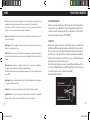
2. PIR SENSOR
The sensor that triggers the trail camera is Passive InfraRed, or PIR. Infrared energy is essentially heat en
-
ergy. The PIR detector operates by sensing a change in the infrared level in its detection zone. This zone is
a cone in the center 10 degrees of the camera’s field of view. The camera establishes an average long-term
infrared level. When this level increased suddenly the PIR detector signals the camera to record a picture
and/or an event. Because of this effect, the PIR detector will be more sensitive at night, when the average
temperature is lower.
In the Setup mode, you can use PIR sensor to determine the detection zone .When the PIR is sensed, the
PIR Sense Indicator will light. The camera’s field of view is a 45 degree cone, centered on the PIR detec
-
tion zone.
OTHER SETUP NOTES
PIR—Passive Infrared Sensor. Senses motion like typical security motion detector. Requires Infrared Energy in addition
to motion to trip sensor to assure detection of live animals.
Event—Any time that the PIR senses motion it counts it as an event. Events are recorded to the SD card in a text file. Events
are recorded continuously during operation.
Image—A digital picture recorded on the SD Card when motion is sensed. Images are taken at the desired delay between
images.
Image Delay—Delay between images taken by camera. This is user-set based on wildlife activity in area.
IR Flash—LED Night Vision Flash. Sends a burst of Infrared Energy which is invisible to the human eye. Especially useful
for night photos when a visible flash is undesirable. (Featured on Model 119900 only)
Camera Flash—Incandescent Flash used for night or low light photography. Typically oversized to achieve greater flash range
for hitting game out further.
SD Card—Memory card used to store images and events inside the trail camera. 32MB card included.
Battery Life—Time that camera will function in the field. Dependent on temperature, number of images and number of
flashes during that time.
Setup—Methods required for setting date/time and camera imaging settings.
Security (4 methods)—One of the most important requirements of any trail camera. Bushnell units have 4 levels—padlock,
tree bracket, cable lock, and software password.
GLOSSARY
12
13
Trail Scout 6LIM.indd 14-15 1/25/05 4:25:48 PM

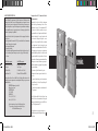
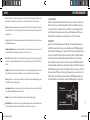
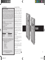
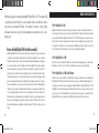
1. MOUNTING:
Mount the trail camera on the tree as shown below.
1. Screw bracket A to the tree.
2. Bolt bracket B on the back of the trail camera.
3. Match bracket B up to bracket A.
4. Then, hang bracket B over bracket A.
5. Finally, insert the padlock and lock when setup is completed.
For extra security, you can use the included cable to wrap around
the tree also.
1. Insert the end with the large lug into bracket A.
2. Then, feed the other end of the cable around the tree and back
through the bracket.
3. Tighten the adjustable locking bolt to hold the cable tightly in
place (B).
USING THE DIGITAL TRAIL SCOUT
3. LASER POINTER
The Model 11-9900 Trail Scout camera has a Laser pointer. When you mount the unit on a tree or any
other fixed surface and cannot sight from behind the Game Camera, you can use the Laser Pointer to align
the unit.
4. REMOTE CONTROLLER
The Model 11-9900 Trail Scout camera has a remote controller attachment with two functions.
Search: If you cannot locate the camera, you can press the SEARCH button,
When the Trail Scout receives the signal the unit’s camera will fire the flash to help you locate it.
Snap: If you want to take a picture by remote control (without PIR activation), press the SNAP button.
14
15
Trail Scout 6LIM.indd 16-17 1/25/05 4:25:49 PM

3. USING THE FILTER
When using LED flash at night-time, remove the FILTER to get satisfactory pictures.
Add the FILTER in daylight to get good quality full color pictures.
FILTER mounts over LENS
OPERATING NOTES
a. The LCD showing “RESUME” means the system is active.
b. The LCD showing “ENTER SUSPEND” means the system is going to suspend.
c. After setting K1 to ON, the system will begin working after a 5 minute delay.
If there is no activity sensed in three minutes, the system will go to SUSPEND.
When the PIR senses activity, the camera will be activated immediately.
17
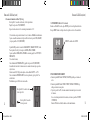
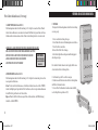
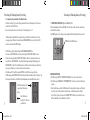
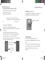
2. Power ON and Setup switch summary:
Turn the knob 90°counterclockwise and open the front cover.
Set the K1 to ON position,
Input correct Password. Default password is “0000”.
(If the password is entered incorrectly 3 times, the unit will
be powered off automatically. If you want to power ON again
you must set K1 back to OFF and then set K1 to ON)
The LCD will display current IMAGE&EVENT counter.
You can press the Up or Down key to see the DATE, TIME, NAME.
If you want to modify DATE, TIME, NAME or password, set K1 to SETUP.
(See instructions)
After finishing SETUP, set K1 back to ON position
The unit will delay 5 minutes before functioning to allow you to clear out of your area.
The functions of K2, K3, and K4 can be set in the SETUP or ON Mode.
After finishing SETUP, close the front cover and turn the knob to 90°clockwise.
Finally, secure the Trail Scout with a padlock.
Turn the knob 90°
counterclockwise to open
Turn the knob 90°
clockwise to close
16
Trail Scout 6LIM.indd 18-19 1/25/05 4:25:50 PM

FRANÇAIS
19
TWO-YEAR LIMITED WARRANTY
Your Bushnell
®
product is warranted to be free of defects in materials and workmanship
for two years after the date of purchase. In the event of a defect under this warranty, we
will, at our option, repair or replace the product, provided that you return the product
postage prepaid. This warranty does not cover damages caused by misuse, improper han-
dling, installation, or maintenance provided by someone other than a Bushnell Autho-
rized Service Department.
Any return made under this warranty must be accompanied by the items listed below:
1)
A check/money order in the amount of $10.00 to cover the cost of postage and handling
2) Name and address for product return
3) An explanation of the defect
4) Proof of Date Purchased
5) Product should be well packed in a sturdy outside shipping carton, to prevent damage in transit,
with return postage prepaid to the address listed below:
IN U.S.A. Send To: IN CANADA Send To:
Bushnell Performance Optics Bushnell Performance Optics
Attn.: Repairs Attn.: Repairs
8500 Marshall Drive 25A East Pearce Street, Unit 1
Lenexa, Kansas 66214 Richmond Hill, Ontario L4B 2M9
For products purchased outside the United States or Canada please contact your local
dealer for applicable warranty information. In Europe you may also contact Bushnell at:
BUSHNELL Performance Optics Gmbh
European Service Centre
MORSESTRASSE 4
D- 50769 KÖLN
GERMANY
Tél: +49 (0) 221 709 939 3
Fax: +49 (0) 221 709 939 8
This warranty gives you specific legal rights.
You may have other rights which vary from country to country.
©2005 Bushnell Performance Optics
FCC Note:
This equipment has been tested and found to comply
with the limits for a Class B digital device, pursuant
to Part 15 of the FCC Rules. These limits are designed
to provide reasonable protection against harmful
interference in a residential installation. This equipment
generates, uses and can radiate radio frequency energy
and, if not installed and used in accordance with the
instructions, may cause harmful interference to radio
communications. However, there is no guarantee that
interference will not occur in a particular installation.
If this equipment does cause harmful interference to
radio or television reception, which can be determined
by turning the equipment off and on, the user is
encouraged to try to correct the interference by one or
more of the following measures:
· Reorient or relocate the receiving antenna.
·
Increase the separation between the equipment and
receiver
.
· Connect the equipment into an outlet on a circuit
different from that to which the receiver is connected.
· Consult the dealer or an experienced radio/TV
technician for help.
Shielded interface cable must be used with the
equipment in order to comply with the limits for a
digital device pursuant to Subpart B of Part 15 of FCC
Rules.
Specifications and designs are subject to change
without any notice or obligation on the part of the
manufacturer.
18
Trail Scout 6LIM.indd 20-21 1/25/05 4:25:52 PM
Page is loading ...
Page is loading ...
Page is loading ...
Page is loading ...
Page is loading ...
Page is loading ...
Page is loading ...
Page is loading ...
Page is loading ...
Page is loading ...
Page is loading ...
Page is loading ...
Page is loading ...
Page is loading ...
Page is loading ...
Page is loading ...
Page is loading ...
Page is loading ...
Page is loading ...
Page is loading ...
Page is loading ...
Page is loading ...
Page is loading ...
Page is loading ...
Page is loading ...
Page is loading ...
Page is loading ...
Page is loading ...
Page is loading ...
Page is loading ...
Page is loading ...
Page is loading ...
Page is loading ...
Page is loading ...
Page is loading ...
Page is loading ...
Page is loading ...
Page is loading ...
Page is loading ...
Page is loading ...
Page is loading ...
Page is loading ...
Page is loading ...
Page is loading ...
Page is loading ...

©2005 Bushnell Performance Optics
www.bushnell.com
Trail Scout 6LIM.indd 112 1/25/05 4:26:24 PM
-
 1
1
-
 2
2
-
 3
3
-
 4
4
-
 5
5
-
 6
6
-
 7
7
-
 8
8
-
 9
9
-
 10
10
-
 11
11
-
 12
12
-
 13
13
-
 14
14
-
 15
15
-
 16
16
-
 17
17
-
 18
18
-
 19
19
-
 20
20
-
 21
21
-
 22
22
-
 23
23
-
 24
24
-
 25
25
-
 26
26
-
 27
27
-
 28
28
-
 29
29
-
 30
30
-
 31
31
-
 32
32
-
 33
33
-
 34
34
-
 35
35
-
 36
36
-
 37
37
-
 38
38
-
 39
39
-
 40
40
-
 41
41
-
 42
42
-
 43
43
-
 44
44
-
 45
45
-
 46
46
-
 47
47
-
 48
48
-
 49
49
-
 50
50
-
 51
51
-
 52
52
-
 53
53
-
 54
54
-
 55
55
-
 56
56
-
 57
57


Bushnell Nov-00 User manual
- Category
- Infrared bulbs
- Type
- User manual
- This manual is also suitable for
Ask a question and I''ll find the answer in the document
Finding information in a document is now easier with AI
in other languages
- italiano: Bushnell Nov-00 Manuale utente
- français: Bushnell Nov-00 Manuel utilisateur
- español: Bushnell Nov-00 Manual de usuario
- Deutsch: Bushnell Nov-00 Benutzerhandbuch
- português: Bushnell Nov-00 Manual do usuário
Related papers
-
Bushnell Trail Scout Remote Setup Owner's manual
-
-
-
-
-
-
-
Bushnell X-8 TRAIL CAM User manual
-
-
Other documents
-
 NICI 37364 Datasheet
-
 Victure HC200 User manual
-
Tasco 119215C Digital Trail Camera User manual
-
Simmons 119225C User manual
-
Renkforce 1362990 Owner's manual
-
BrickHouse Security B-L4G Owner's manual
-
Hama 69003553 Owner's manual
-
Swann OutbackCam Operating instructions
-
Marshall UHF 433-434MHz RT Plus UHF Transmitter Operating instructions
-
Marshall Scout UHF Transmitter Operating instructions

