Page is loading ...

WARRANTY
The 85XT Digital Multimeter is warranted against any defects of material or workmanship
within a period of one (1) year following the date of purchase of the multimeter by the original
purchaser or original user.
Any multimeter claimed to be defective during the warranty period should be returned with
proof of purchase to an authorized Wavetek Meterman Service Center or to the local Wavetek
Meterman dealer or distributor where your multimeter was purchased. See maintenance section
for details.
Any implied warranties arising out of the sale of a W
avetek Meterman multimeter, including
but not limited to implied warranties of merchantability and fitness for a particular purpose, are
limited in duration to the above stated one (1) year period. Wavetek Meterman shall not be
liable for loss of use of the multimeter or other incidental or consequential damages, expenses,
or economical loss or for any claim or claims for such damage, expenses or economical loss.
Some states do not allow limitations on how long implied warranties last or the exclusion or
limitation of incidental or consequential damages, so the above limitations or exclusions may
not apply to you.
This warranty gives you specific legal rights, and you may also have other rights which vary
from state to state.
D GEWÄHRLEISTUNG
Die Digitale Multimeter Modelle 85XT ist ab Kaufdatum für ein (1) Jahr gegen Material- und
Herstellungsfehler gewährleistet. Siehe Kapitel "Unterhalt und Reparatur" für Einzelheiten.
Implizierte Schadeforderungen sind auch auf ein Jahr beschränkt. W
avetek Meterman ist nicht
ansprechbar für Gebrauchsverluß oder Folgeschäden, Ausgaben, Gewinnverluß, usw.
E GARANTIA
Este Multímetro Digitale Modelo 85XT está garantizado contra cualquier defecto de material
o de mano de obra durante un periodo de un (1) año contado a partir de la fecha de
adquisición. En la sección de "Mantenimiento y Reparación" se explican los detalles relativos a
reparaciones en garantía.
Cualquier otra garantía implícita está también limitada al periodo citado de un (1) año.
Wavetek Meterman no se hará responsable de pérdidas de uso del multí metro, ni de ningún
otro daño accidental o consecuencial, gastos o pérdidas económicas, en ninguna reclamación a
que pudiera haber lugar por dichos daños, gastos o pérdidas económicas.
F GARANTIE
Le multimètre digitaux, Modèle 85XT est garanti pour un (1) an à partir de la date d’achat
contre les défauts de matériaux et de fabrication. Voir chapitre "Maintenance et Réparation" pour
plus de détails.
T
oute garantie impliquée est également limitée à un an. Wavetek Meterman ne peut être tenu
responsable pour perte d’utilisation ou autres préjudices indirects, frais, perte de bénéfice, etc.
85XT.Man.07.00 9/11/00 7:53 PM Page 36

- 1 -
CONTENTS
D • Inhalt
E • Contenidos
F • Contenu
EXPLANATION OF SYMBOLS
D • Erklärung der Symbole = E • Significado de los símbolos = F • Explication des Symboles
Safety Information ............................................... 2
Instrument Familiarization.................................... 4
Measurement Procedures ................................... 6
Specifications ................................................... 18
Maintenance and Repair .................................... 27
Sicherheitsinformationen .................................... 2
Vorstellung des Gerätes....................................... 4
Meßprozeduren ................................................... 6
Spezifikationen .................................................. 20
Unterhalt und Reparatur .................................... 27
Información de seguridad ................................... 2
Familiarización con el instrumento ...................... 4
Procedimientos de medida .................................. 6
Especificaciones ............................................... 22
Mantenimiento y reparación .............................. 27
Informations de Sécurité ..................................... 3
Présentation de l’Appareil ................................... 4
Procédures de Mesure ........................................ 6
Spécifications ................................................... 25
Maintenance et Réparation ................................ 27
Attention! Refer to Operating Instructions •D• Achtung! Bitte Anleitung
lesen •E• ¡Atención! Consulte el Manual de Instrucciones
•F• Attention! Consultez le manuel.
Ground connection •D• Erdanschluß •E• Conexión de tierra
•F• Connection de terre.
Alternative current •D• Wechselstrom •E• Corriente alterna
•F• Courant alternatif.
Direct current •D• Gleichstrom •E• Corriente continua
•F• Courant continu.
Dangerous voltage may be present at terminals •D• Eine gefährliche
Spannung kann an den Eingängen anliegen •E• Peligro: puede haber
alta tensión en los terminales •F• Une tension dangereuse peut être
présente aux entrées.
This instrument has double insulation •D• Dieses Gerät ist doppelt
geisoliert •E• Este instrumento tiene doble aislamiento •F• Cet
appareil est prévu d’une double isolation.
85XT.Man.07.00 9/11/00 7:53 PM Page 1

WARNINGS AND PRECAUTIONS
■ This instrument is EN61010-1 certified for Installation Category II. It is
recommended for use with local level power distribution, appliances, portable
equipment, etc, where only smaller transient overvoltages may occur, and not for
primary supply lines, overhead lines and cable systems. ■ Do not exceed the
maximum overload limits per function (see specifications) nor the limits marked
on the instrument itself. ■ Exercise extreme caution when: measuring voltage
>20V // current >10mA // AC power line with inductive loads // AC power line
during electrical storms // current, when the fuse blows in a circuit with open
circuit voltage >600 V // servicing CRT equipment. ■ Inspect DMM, test leads
and accessories before every use. Do not use any damaged part. ■ Never ground
yourself when taking measurements. Do not touch exposed circuit elements or
probe tips. ■ Always measure current in series with the load – NEVER ACROSS a
voltage source. Check fuse first. ■ Never replace a fuse with one of a different
rating. ■ Do not operate instrument in an explosive atmosphere.
D • Warnungen und Vorsichtsmaßnahmen
■
Dieses Gerät ist EN61010-1 zertifiziert für Installationsklasse II. Anwendung ist
empfohlen für lokale Stromverteilung, Haushaltgeräte, tragbare Geräte, usw, wo nur
kleinere Spannungsspitzen auftreten können, und nicht für primäre Stromverteilung
und Hochspannungsleitungen.
■
Überschreiten Sie nie die kontinuierlichen
Überlastgrenzen per Funktion (siehe Spezifikationen) oder andere Grenzen welche
auf dem Gerät markiert sind.
■
Äußerste Vorsicht beim Messen von: Spannung
>20V // Strom >10mA // Netzstrom bei Gewittern // Netzstrom mit induktiver Last //
Strom, wenn die Sicherung durchbrennt in einem Schaltkreis mit Leerlaufspannung
>600V // beim Messen an Bildröhrgeräten (hohe Spannungsspitzen)
■
Unsersuchen Sie Gerät, Meßkabel, Verbinder, usw. vor jeder Messung. Beschädigte
Teile nicht verwenden
■
Meßspitzen und Stromkreis während der Messung nicht
berühren • Sich selbst isolieren !
■
Bei Strommessung, Multimeter immer in Serie
mit Schaltkreis verbinden – Nie parallel mit Schaltkreis.
■
Sicherung immer mit
gleichwertiger ersetzen.
■
Gerät nicht in explosiver Umgebung verwenden.
E • Advertencias y Precauciones
■
Este instrumento está homologado según EN61010-1 para la Categoría de
Instalación II. Su uso está recomendado en distribución local de energía,
electrodomésticos, equipos portátiles, etc, donde solamente pueden producirse
bajos niveles transitorios de sobretensión; pero no en líneas principales de
suministro, líneas aéreas y sistemas de cableado.
■
No supere nunca los límites de
- 2 -
85XT.Man.07.00 9/11/00 7:53 PM Page 2

- 5 -
COMV- mA 20A
750
200
200m
200m
20
2
2k
FUSED
FUSED
MAX
CAT.
II
85XT
VV
Hz
1000V
750V
200mA MAX
True RMS
MAX
DC
AC
%V
mV
HOLD
ON/OFF
2m
200
DUTY%
2k
200
20k
200k
2M
20M
200m
2m
1000
20
2
200
200m
200
H
20k
200
AmA
KHz
M
V
K
k
20m
20A
20m
20A
A
A
20A/60sec
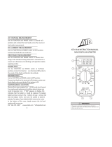
4-1/2 digit LCD; function and unit indicators
4-1/2 Digit LCD ; Funktions- und Einheitsanzeigen
LCD de 4-1/2 dígitos; indicadores de función y unidades
LCD 4-1/2 digits ; indications de fonctions et d’unités
Low Battery
Batterie entladen
Pila baja
Pile déchargée
On/Off Switch
Ein/Aus Schalter
Interruptor de
encendido
(on/off)
Mise-en-
marche/Arrêt
Display Hold
button
Anzeigesperre
Display Hold
button
Maintien de lecture
Function/Range
Selector
Funktions-/Bereichs-
Schalter
Selector de
Función/Escala
Sélecteur fonctions/
calibres
mA Input for measure-
ments up to 200mA
mA Eingang für
Messung bis 200mA
Entrada mA para
medidas hasta 200mA
Entrée mA pour
mesure jusqu’à 200mA
20 A Input
20A Eingang
Entrada 20A
Entrée 20A
V-Ω Input (Red). High input for
voltage and resistance
V-Ω Eingang (Rot). Hoch für
Spannung und Widerstand
Entrada V-Ω (Rojo). Entrada
“positiva” para tensión y resistencia
Entrée V-Ω (Rouge). Haut pour
tension et résistance
COM Input (Black) – common or low
input for all measurements
COM Eingang (Schwarz) –
Referenzpunkt für alle Messungen
Entrada COM (Negro) - entrada común
o “negativa” para todas las medidas
Entrée COM (Noir) – commun ou bas
pour toutes mesures
85XT
85XT.Man.07.00 9/11/00 7:53 PM Page 5

MEASURING PROCEDURES
General Procedures: ❶ When connecting or disconnecting test leads to/from
a circuit, always first turn off power to device or circuit being tested and discharge
all capacitors. ❷ If the magnitude of a signal to be measured is not known, set
selector switch to highest range first and reduce until satisfactory reading is
obtained. ❸ Strictly observe the max input limits.
D • Meßprozeduren
Allgemein:
❶
Vor Verbinden und Trennen der Meßkabel mit dem Schaltkreis,
diesen abschalten und Kondensatoren entladen.
❷
Bei unbekannter Signalgröße,
bei höchstem Bereich beginnen und dann niedriger schalten bis gute Auflösung
erreicht wird.
❸
Maximale Grenzen nicht überschreiten.
E • Procedimientos de medida
Procedimientos generales:
❶
Antes de conectar o desconectar las puntas de
prueba a/de un circuito, apague siempre el dispositivo o circuito sometido a prueba
y descargue todos los condensadores.
❷
Si no conoce la magnitud de la señal que
va a medir, seleccione en primer lugar la escala más alta y vaya reduciéndola hasta
obtener una lectura satisfactoria.
❸
Observe estrictamente los límites máximos de
entrada.
F • Procédures de Mesure
Général:
❶
Avant de connecter ou de déconnecter les cordons de test, coupez
l’alimentation du circuit mesuré et déchargez les condensateurs.
❷
Si la magnitude
du signal n’est pas connue, commencez par la gamme la plus élevée, et diminuez
ensuite jusqu’à obtenir une bonne lecture.
❸
Ne dépassez pas les limites d’entrée.
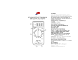
DC AND AC VOLTAGE MEASUREMENT (see Fig. 1)
❶ Connect red test lead to V-Ω Input and black lead to COM. ❷ Set function/
range switch to the desired AC or DC voltage range. ❸ Touch Probe tips across
voltage source (in parallel with circuit). ❹ Read value (and polarity for DC
- 6 -
E • Préparation pour l’Emploi - Déballage
Votre emballage doit contenir: un multimètre, un jeu de câbles de mesure (un
rouge, un noir), une pile 9V (installée), un fusible de réserve (dans l’appareil), une
carte de garantie et ce manuel. Si une pièce manque ou est endommagée, ramenez
l’ensemble au point de vente pour un échange.
85XT.Man.07.00 9/11/00 7:53 PM Page 6

- 7 -
COMV- mA 20A
750
200
200m
200m
20
2
2k
FUSED
FUSED
MAX
CAT.
II
85XT
VV
Hz
1000V
750V
200mA MAX
True RMS
MAX
DC
HOLD
ON/OFF
2m
200
DUTY%
2k
200
20k
200k
2M
20M
200m
2m
1000
20
2
200
200m
200
20k
200
V
k
20m
20A
20m
20A
A
A
20A/60sec
red/rot/
roja/rouge
2
1
3
4
V &
V
> 20V
Fig. 1
5.0
4.0
3.0
2.5
1.0
2%
0%
5%
4%
3%
100%806040200
Wave form, Crest Factor
Wellenform, Crest Factor
Forma de onda, Factor de Cresta
Forme d'onde, Facteur Crête
Additional correction from 1.5 to 5.0
Zusätzliche Korrektur von 1.5 bis 5.0
Corrección aditional para 1.5 a 5.0
Correction supplém. de 1.5 à 5.0
Input RMS, Percentage of Full-Scale • Effektiv-Wert Eingang, % vom Endbereich
Valor eficaz de entrada, % del fondo de escala • Entrée effective, % pleine échelle
Table 1
85XT.Man.07.00 9/11/00 7:53 PM Page 7

DC AND AC CURRENT MEASUREMENT (See Fig. 2)
❶ Connect red test lead to the mA Input for current measurements up to 200mA
or to the 20A input for current measurements to 20A (15 to 20A for 30 seconds).
Connect black test lead to COM Input Connector. ❷ Set the Function/Range
switch the desired DC or AC current range corresponding to the selected input
jack. If in doubt choose to the highest setting first. ❸ Open circuit in which
current is to be measured. Securely connect test leads in series with the load. ❹
Turn on power to circuit being tested. ➎ Read current value on Digital Display.
Note: Each current input has a protective fuse installed. If fuse does blow, replace
with same.
Note for AC Measurements: See AC/DC Voltage measurement.
- 9 -
COMV- mA 20A
750
200
200m
200m
20
2
2k
FUSED
FUSED
MAX
CAT.
II
85XT
VV
Hz
1000V
750V
200mA MAX
True RMS
MAX
DC
HOLD
ON/OFF
2m
200
DUTY%
2k
200
20k
200k
2M
20M
200m
2m
1000
20
2
200
200m
200
20k
200
AmA
k
20m
20A
20m
20A
A
A
20A/60sec
Discharge capacitors
Kondensatoren entladen
Descargue los condensadores
D charger les condensateurs
3a
3b
3d
4
5
red/rot/
roja/rouge
A A
1
2
Fig. 2
85XT.Man.07.00 9/11/00 7:53 PM Page 9

- 10 -
D •Gleich- und Wechselstrommessung (siehe Fig. 2)
❶
Rotes Meßkabel für Messungen bis 200mA mit dem mA Eingang verbinden, oder
für Messungen bis 20A mit dem 20A Eingang (15 bis 20A für 30 Sekunden).
Schwarzes Meßkabel mit COM verbinden.
❷
Funktionsschalter in Übereinstimmung
mit gewähltem Eingang auf gewünschten DCA oder ACA Bereich stellen.
❸
Meßkreis öffnen. Meßspitzen sicher in Serie mit dem Stromkreis verbinden.
❹
Meßkreis einschalten.
➎
Stromwert ablesen.
Anmerkung für AC Meßungen: Siehe Spannungsmessung.
E • Medidas de corriente CC y CA (vea Fig. 2)
❶
Conecte la punta de prueba roja a la entrada de mA para medidas de corriente
hasta 200 mA, o a la entrada de 20A para medidas de corriente hasta 20 A. Conecte
la punta de prueba negra a la entrada COM.
❷
Ponga el selector de función e la
escala deseada de corriente CA o CC, según la entrada seleccionada. En caso de
duda, seleccione la escala más alta en primer lugar.
❸
Abra el circuito en el que
vaya a medir la corriente. Conecte con seguridad las puntas de prueba, en serie con
la carga.
❹
Conecte la alimentación del circuito sobre el que va a medir.
➎
Lea el
valor de la corriente en el visualizador.
Nota para medidas de CA: Vea Medidas de tensión CA/CC
F • Mesure de Courant CC et CA (voir fig. 2)
❶
Connectez le cordon rouge à l’entrée mA pour mesures jusqu’à 200mA et à
l’entrée 20A pour mesures jusqu’à 20A (15 à 20A pendant 15 secondes). Connectez
le cordon noir à l’entrée COM.
❷
Placez le sélecteur sur le calibre souhaité en DCA
(cc) ou ACA (ca), en concordance avec l’entrée utilisée.
❸
Ouvrez le circuit à
mesurer et connectez les pointes de touche solidement en série avec le circuit.
❹
Mettez le circuit sous tension.
➎
Lisez la mesure.
Note pour mesures en CA: Voir mesures de tension.
RESISTANCE MEASUREMENT (See Fig. 3)
❶ Turn off power to the resistance to be measured and discharge any capacitors.
Any voltage present during a resistance measurement will cause inaccurate
readings.❷ Connect red test lead to V•Ω Input and black test lead to COM Input.
❸ Set Function/Range Switch to the desired Ω position. ❹ Connect test leads to
resistance or circuit to be measured. ➎ Read resistance value on Digital Display.
Open circuits will be displayed as an overload condition.
Note: For low resistance values, measure resistance of test leads first by
contacting probe tips, and deduct this value from actual measurement.
85XT.Man.07.00 9/11/00 7:53 PM Page 10

Un circuit ouvert est affiché par un dépassement de calibre.
Note: Pour des faibles valeurs de résistance, mesurez d’abord la résistance des
cordons de test (en court-circuitant les pointes), et déduisez cette valeur de la
mesure ultérieure.
DIODE AND TRANSISTOR TEST (See Fig. 4)
The diode test measures the voltage drop across a diode junction. ❶ Connect the
red test lead to the V•Ω Input and the black test lead to the COM Input. ❷ Set the
Function/range switch to position. ❸ Apply probe tip of red lead to the
anode and of black lead to the cathode of the diode. ❹ The meter’s display
indicates the forward voltage drop (approximately 0.6V for silicon diode or 0.4V
for germanium diode). Meter will display overload condition for an open diode. ➎
Reverse test lead connections to the diode to perform a reverse bias test. Overload
indicates a good diode. Notes: Overload conditions for both reverse and forward
bias tests indicate an open diode. A low voltage reading for both bias tests
indicates a shorted diode. If the diode is shunted by a resistor of 1000 ohms or
less, it must be removed from the circuit before taking the measurement. Bipolar
transistor junctions may be tested in the same manner described above.
D • Dioden- und Transistortest (siehe Fig. 4)
Der Diodentest zeigt den Spannungsabfall über den Diodendurchgang
❶
Rotes
Meßkabel mit V-Ω Eingang und schwarzes mit COM Eingang verbinden.
❷
Funktionsschalter auf stellen.
❸
Meßkabel mit Diode verbinden – rotes mit
Anode; schwarzes mit Kathode.
❹
Spannungsabfall in Durchlaßrichtung ablesen
(ung. 0.6V für eine Silikon-Diode und 0.4V für eine Germaniumdiode. Eine offene
Diode wird mit Überlast angezeigt.
➎
Verbindung umdrehen um in Sperrrichtung zu
messen. Überlast zeigt eine gute Diode an. Anmerkung: Überlast in beiden
Richtungen zeigt eine offene Diode an; eine niedrige Ablesung eine
kurzgeschlossene Diode. Transistorübergänge können wie Dioden getestet werden.
E • Comprobación de diodos y transistores (vea Fig. 4)
En esta prueba se mide la caída de tensión en la unión del diodo.
❶
Conecte la
punta de prueba roja a la entrada V-Ω y la negra a la entrada COM.
❷
Ponga el
selector en la posición .
❸
Aplique la punta de prueba roja al ánodo del
diodo y la negra al cátodo.
❹
El visualizador indica la caída de tensión directa
(aproximadamente 0.6 V para diodos de silicio, o 0.4 V para diodos de germanio).
Una unión abierta se indica como condición de sobrecarga.
➎
Invierta la conexión
de las puntas de prueba para verificar la polarización inversa del diodo. La
condición de sobrecarga indica un diodo en buen estado.
Notas: La condición de sobrecarga en ambos sentidos indica un diodo abierto. Un
- 13 -
85XT.Man.07.00 9/11/00 7:53 PM Page 13

valor bajo de tensión en ambos sentidos indica un diodo cortocircuitado. Si el diodo
tiene en paralelo una resistencia de 1000 Ω o menos, ésta deberá extraerse del
circuito antes de hacer la medida. Las uniones de un transistor bipolar equivalen a
diodos y se comprueban como tales.
F • Test de Diodes et de Transistors (voir Firg. 4)
Le test de diodes affiche la chute de tension à travers le transistor.
❶
Connectez le
cordon rouge à l’entrée V–Ω et le noir à l’entrée COM.
❷
Placez le sélecteur sur
.
❸
Connectez les pointes de touche à la diode – le rouge à l’anode, le noir à
la cathode.
❹
Lisez la chute de tension en direction passante (environ 0.6V pour
une diode au Si; 0.4V pour une diode au Ge. Une diode ouverte est affichée par “1”
(dépassement de calibre).
➎
Inversez la connection pour mesurer en direction de
bloquage. Une bonne diode est affichée par “1”. Notes: “1” dans les deux
directions indique une diode ouverte; une lecture basse indique une diode court-
circuitée. Les jonctions de transistors peuvent être testées comme des diodes.
CONTINUITY TEST
The Continuity test checks electrical continuity between two contact points. ❶ Set
the Function/Range switch to . ❷ Plug the black test lead into the COM jack
and connect the test lead tip to one of the contact points. ❸ Plug the red test lead
into the V-Ω jack and connect its test lead point to the other contact point. ❹ The
internal beeper emits a tone when resistance is less than approx. 100Ω.
D • Durchgangstest
❶
Funktionsschalter auf stellen.
❷
Rotes Meßkabel mit V•Ω Eingang und
schwarzes mit COM Eingang verbinden.
❸
Meßspizen mit Schaltkreis verbinden. ❹
Bei R ≤100Ω wird ein akustisches Signal abgegeben.
E • Prueba de continuidad
❶
Ponga el selector de función en la posición .
❷
Conecte la punta de prueba
negra a la entrada COM y toque uno de los puntos de contacto con el extremo.
❸
Conecte la punta de prueba roja a la entrada V-Ω y toque el otro punto de contacto
con el extremo.
❸
El zumbador interno emite un tono cuando la resistencia es
menor de aproximadamente 100 Ω.
F • Test de Continuité
❶
Placez le sélecteur sur .
❷
Connectez le cordon rouge à l’entrée V•Ω et le
cordon noir à l’entrée COM.
❸
Connectez les pointes de touche au circuit. ❹ Un
signal sonore retentit pour R ≤100Ω.
- 14 -
85XT.Man.07.00 9/11/00 7:53 PM Page 14

FREQUENCY/DUTY CYCLE MEASUREMENT
❶ Connect the red test lead to the V-Ω input and the black test lead to the COM
input. ❷ Set the function/range switch to the desired Hz position. ❸ Apply probe
tips to signal source and read frequency value on display. ❹ Set function/range
switch to DUTY% to measure the duty cycle of the signal (0 to 90%).
Note: With the function/range switch in Hz position, and probe tips not applied to
a circuit, the display shows a certain reading. With probe tips shorted, the reading
is zero. This initial reading has no influence on the accuracy of the measurement.
D • Frequenz- und Taktverhältnis-Messung
❶
Rotes Meßkabel mit V-Ω Eingang und schwarzes mit COM Eingang verbinden.
❷
Funktionsschalter auf gewünschte Hz Position stellen.
❸
Meßspitzen mit
Signalquelle verbinden und Meßwert ablesen.
❹
Funktionsschalter auf DUTY%
stellen um das Taktverhältnis abzulesen (0 bis 90%).
Anmerkung: Mit dem Funktionsschalter auf Hz Position und freistehenden
Meßspitzen, wird ein bestimmter Wert angezeigt. Mit kurzgeschlossenen Meßspitzen
wird Null angezeigt. Der initiale Wert hat keinen Einfluß auf die Genauigkeit des
Meßwertes.
E • Medidas de Frecuencia y Ciclo de Trabajo
❶
Conecte la punta de prueba roja a la entrada V-Ω y la negra a la entrada COM.
❷
ponga el selector de función en la posición deseada de Hz.
❸
Aplique las puntas de
prueba a la fuente se señal y lea el valor de la frecuencia en el visualizador.
❹
Ponga el selector de función en DUTY% para medir el ciclo de trabajo de la señal (0
a 90%).
Nota: Con el selector en la posición Hz, si no se aplican las puntas de prueba a un
conectar a un circuito, el visualizador presenta un valor arbitrario. Si se cortocir-
ciuitan las puntas de prueba, el valor indicado es cero. Este valor inicial no tiene
ninguna influencia en la precisión de la medida.
F • Mesure de Fréquence et du Rapport Cyclique
❶
Connectez le cordon rouge à l’entrée V-Ω et le cordon noir à l’entrée COM.
❷
Placez le sélecteur sur la position Hz désirée.
❸
Connectez les pointes de touche au
circuit et lisez la valeur sur l’afficheur.
❹
Placez le sélecteur sur DUTY% et lisez le
rapport cyclique (0 à 90%).
Note: Avec le sélecteur sur une position Hz et les pointes de touche séparées, une
certaine valeur est affichée. Avec les pointes de touche court-circuitées, cette valeur
est zéro. La valeur initiale n’a pas d’influence sur la précision du résultat de mesure.
- 15 -
85XT.Man.07.00 9/11/00 7:53 PM Page 15

SPECIFICATIONS
SPECIFICATIONSSPECIFICATIONS
SPECIFICATIONS
General Specifications
General SpecificationsGeneral Specifications
General Specifications
Display: 4 1/2 digit LCD, 19999 counts,
0.7" (17.8mm) high numerals, unit
annunciators and function symbols
Polarity Indication: Automatic, positive
implied, negative indicated
Zero Adjustment: Automatic
Overrange Indication: "1 "
Low Battery Indication:
+ -
.
Change battery immediately.
Display Update Rate: 2/sec, nominal
Operating Temperature: 0°C to 50°C, 0
to 70% Relative Humidity
Storage Temperature: -20°C to 60°C, 0 to
80% RH with battery removed.
Environment: Indoor use, Altitude up to
2000m
Temperature coefficient: 0.1 x (spec.
accur.) per
°
C (0-18°C, 28-50°C)
Power: Standard 9-volt battery, NEDA 1604,
JIS 006P, IEC 6F22
Auto Power Off: 50 minutes after no function
or range change
Battery Life (Typical): 300 hrs alkaline
Dimensions (H x W x D): 18.3 x 7.9 x
3.8 cm, (7.2 x 3.1 x 1.5 inches)
Weight (including battery): 311 grams (11
ounces)
Accessories: Test leads, 0.5A / 250V spare
fuse, battery, operator's manual.
Safety: Meets EN61010-1 Cat II-1000V;
Pollution degree 2; Class II.
EMC: Meets EN50081-1, EN50082-2
This product complies with
requirements of the following
European Community
Directives: 89/336/EEC (Electromagnetic
Compatibility) and 73/23/EEC (Low Voltage) as
amended by 93/68/EEC (CE Marking).
However,
electrical noise or intense electromagnetic fields
in the vicinity of the equipment may disturb the
measurement circuit. Measuring instruments will
also respond to unwanted signals that may be
present within the measurement circuit. Users
should exercise care and take appropriate
precautions to avoid misleading results when
making measurements in the presence of
electronic interference.
Electrical Specifications
Electrical SpecificationsElectrical Specifications
Electrical Specifications
Accuracies at 23°C
±
5°C, < 75% RH.
DC Volts
DC Volts DC Volts
DC Volts
Ranges; 200mV, 2, 20, 200, 1000V
Accuracy, all rgs: :
±
(0.05% rdg +3 dgt)
Resolution, 200mV Range: 10
µ
V
Input Impedance: 10M
Ω
NMMR (50-60Hz): >55dB
CMRR (up to 1000VDC: >110dB
OL Protection, 200mV Range: 350VAC
RMS/ 500VDC (15 seconds)
Other Ranges: 750V RMS/1000VDC
AC Volts
AC Volts AC Volts
AC Volts -
--
-True RMS
True RMS True RMS
True RMS
Ranges: 200mV, 2, 20, 200, 750V
Accuracy,50- 500Hz*:
200mV-200V rgs:
±
(1.0% rdg + 10 dgt)
750V range:
±
(2.0% rdg + 20 dgt)
Accuracy, 500Hz -2kHz*:
200mV-200V rgs:
±
(2.0% rdg + 20 dgt)
* In the 200mV range accuracy is for >
10% of range
Resolution, 200mV Range: 10
µ
V
Conversion: AC coupled, True RMS
responding
Crest Factor for True RMS: 5 : 1
- 18 -

Input Impedance: 10M
Ω
OL Protection, 200mV Range: 350VAC
RMS / 500VDC (15 seconds)
Other Ranges: 750V RMS/ 1000VDC
DC Current
DC Current DC Current
DC Current
Ranges: 200µA, 2, 20, 200mA, 20A *
*15 to 20A for 30 sec max
Resolution, 200
µ
A range: 10nA
Accuracy, 200
µ
A to 200mA ranges:
±
(0.5% rdg + 5 dgt)
20A range:
±
(2.0% rdg + 10 dgt)
Burden Voltage:
200
µ
A to 20A ranges: 350mVDC
200mA range: 650mVDC
20A range: 850mVDC
OL Protection, mA input: 0.5A/250V fast
blow ceramic fuse
20A input: 20A/600V fast blow ceramic fuse
AC Current. True RMS
AC Current. True RMS AC Current. True RMS
AC Current. True RMS
Ranges: 200µA, 2, 20, 200mA, 20A*
*.15 to 20A for 30 sec max
Resolution, 200
µ
A range: 10nA
Accuracy (50Hz .1 kHz), 200
µ
A to
200mA rgs:
±
(0.8% rdg + 10 dgt)
20A rg:
±
(2.5% rdg + 10 dgt)
Conversion: AC coupled, True RMS
responding
Crest Factor for True RMS: 5 :1
Burden Voltage:
200
µ
A to 20A ranges: 350mVDC
200mA range: 650mVDC
20A range: 850mVDC
OL Protection, mA input: 0.5A/250V fast
blow ceramic fuse
20A input: 20A/600V fast blow ceramic fuse
Resistance
Resistance Resistance
Resistance
Ranges: 200
Ω
, 2, 2, 20, 200k
Ω
, 2, 20M
Ω
.
Resolution, 200
Ω
, range: 10m
Ω
Accuracy, 200 W rg:
±
(0.25%rdg + 10 dgt)
2 to 200k
Ω
rgs:
±
(0.15% rdg + 3 dgt)
2M
Ω
rg:
±
(0.25% rdg + 10 dgt)
20M
Ω
rg:
±
(1.0% rdg + 10 dgt)
OL Protect. all rgs: 500VDC or AC RMS
Open Circuit Volts, all rgs: 3.2VDC typ.
Con
ConCon
Continuity
tinuity tinuity
tinuity
Audible Indication, 200
Ω
range:
at R < 75
Ω
Response time: 500ms approx
Open circuit volts: 3.2VDC typical
OL Protection: 500VDC or AC RMS
Diode Test
Diode Test Diode Test
Diode Test
Test Current: 1mA (approx.)
Test Voltage: 3.2VDC typical
Accuracy:
±
(0.8% rdg + 1 dgt)
Display, 2V range: Forward Junction Voltage
OL Protection: 500VDC or AC RMS
Frequency Measurement
Frequency MeasurementFrequency Measurement
Frequency Measurement
Ranges: 2, 20, 200kHz
Resolution, 2kHz range: 0.1 Hz
Accuracy:
±
(0.5% rdg + 10 dgt)
Input Impedance, all ranges: 10M
Ω
// 110pF
Sensitivity, Sine Wave: 50mV RMS min (at >
30% and < 70% duty cycle: 400mV RMS
min.)
Minimum input range: 2kHz: 10Hz; 20kHz:
> 60 dgt; 200kHz: > 60 dgt.
OL Protection: 500VDC or AC RMS
Duty Cycle
Duty Cycle Duty Cycle
Duty Cycle
Range: 0 to 90.0% Resolution: 0.1 %
Pulse Width: > 10
µ
sec min
Frequency Range: 40Hz to 20kHz
Accuracy, (5V Logic):
±
(2.0%rdg + 10 dgt)
OL Protection: 500VDC or AC RMS
- 19 -

Optional Accessories
DL243C Standard Test Lead Set
DL248C Deluxe Test Lead Set
TL245 Standard Replacement Test Leads
TL35A Test Leads with Alligator Clips
CT231A 150A AC Current Clamp
CT232A 1000A AC Current Clamp
CT234A 400A AC Current Clamp
CT235 1000A AC/DC Clamp
CT236A 500A AC Clamp (mV output)
CT237 200A AC/DC Current Clamp
CT238 20A AC/DC Current Clamp
RF241 650MHz RF Probe
TC 253A Temperature Converter
(900°C/1652°F)
VC221A Padded Vinyl Case. Fits meter &
holster.
VC231 Padded Vinyl Case. Fits meter
without holster
H30Y Protective Holster
VC30 Vinyl Carrying Case (for meter and
holster)
H V231-10 High Voltage Probe
D • Optionszubehör
DL243C Standard Meßkabelsatz
DL248C Deluxe Meßkabelsatz
TL245 Ersatzsicherheitsmeßkabel
TL35A Ein Meßkabelsatz, ein Paar
Krokodilkemmen
CT231A 150A AC Stromzange
CT232A 1000A AC Stromzange
CT234A 400A AC Stromzange
CT235 1000A AC/DC Stromzange
CT236A 500A AC Stromzange (mV
Ausgang)
CT237 200A AC/DC Stromzange
CT238 20A AC/DC Stromzange
RF241 650MHz RF Meßkopf
TC 253A Temperatur/Spannungsumsetzer
(900°C/1652°F)
H30Y Schutzholster
VC221A Gepolsterte Vinyl-Tragetasche (für
Meter und Holster)
VC231 Gepolsterte Vinyl-Tragetasche (für
Meter ohne Holster)
VC30 Vinyl Tragetasche (für Meter und
Holster)
HV231-10 Hochspannungssonden
E • Accesorios opcionales
DL243C Juego de puntas de prueba
DL248C Puntas de prueba (calidad
especial)
TL245 Puntas de prueba de repuesto
TL35A Puntas de pruebba con dos d
cocodrilo
CT231A Pinza de corriente 150 A CA
CT232A Pinza de corriente 1000 A CA
CT234A Pinza de corriente 400 A CA
CT235 Pinza de corriente 1000 A
CA/CC
CT236A Pinza de corriente 500 A CA
(salida mV)
CT237 Pinza de corriente 200 A CA/CC
CT238 Pinza de corriente 20 A CA/CC
RF241 Sonda de RF 650 MHz
TC253A Convertidor de temp.
(900ºC/1652ºF)
VC221A Estuche de vinilo acolchado
Admite el medidor y funda
VC231 Estuche de vinilo acolchado
Admite el medidor con funda
H30Y Funda protectora
VC30 Estuche de transporte de vinilo
(para medidor y funda
protectora)
FP385 Fusibles 0.5A/500V.
HV231-10 Sonde haute tension
F • Accessoires en Option
DL243C Cordons de mesure standards
DL248C Cordons de mesure Deluxe
TL245 Cordons de mesure de rechange
TL35A Cordons de mesure avec pjnces
crocodile
CT231A Pince de courant CA 150A
CT232A Pince de courant CA 1000A
CT234A Pince de courant CA 400A
CT235 Pince de courant CA/CC1000A
CT236A Pince de courant CA 500A (sortie
mV)
CT237 Pince de courant CA/CC 200A
CT238 Pince de courant CA/CC 20A
RF241 Sonde RF 650MHz
TC 253A Convertisseur Temp.
(900°C/1652°F)
VC221A Sacoche en vinyl rembourrée pour
instrument avec gaine
VC231 Sacoche en vinyl rembourrée pour
instrument sans gaine
H30Y Holster de protection
VC30 Sacoche en vynil (pour instrument
et holster)
VC231 Sacoche en vinyl rembourrée pour
HV231-10 Sondeo grande tensión
- 26 -
85XT.Man.07.00 9/11/00 7:53 PM Page 26

TROUBLESHOOTING / MAINTENANCE
If there appears to be a malfunction during the operation of the meter, the
following steps should be performed in order to isolate the cause of the problem:
❶ Check the battery. ❷ Review the operating instructions for possible mistakes in
operating procedure. ❸ Inspect and test the test probes for a broken or
intermittent connection. ❹ Inspect and test the fuse. See Fuse Replacement.
Except for the replacement of the battery or fuse, repair of the multimeter should
be performed only by a Factory Authorized Service Center or by other qualified
instrument service personnel.
The front panel and case can be cleaned with a mild solution of detergent and
water. Apply sparingly with a soft cloth and allow to dry completely before using.
D • Fehlersuche/Unterhalt
Prüfen Sie zuerst folgende Fehlerquellen: Meßkabel (Brüche), Anschluß, Zustand von
Batterie und Sicherung, richtiger Meßvorgang, Eingangs- und Bereichsgrenzen, usw.
Mit Ausnahme des Batterie- und Sicherungswechsels soll jede Reparatur nur durch
eine durch Wavetek anerkannte Servicestelle durchgeführt werden.
Das Gerät kann mit einer milden Seifenlösung gereinigt werden. Sparsam auftragen
und vor Gebrauch gut trocknen lassen.
E • Localización de Averías/Maintenimiento
Para identificar la causa del problema: Compruebe la pila; revise las instrucciones
de uso; inspeccione las puntas de prueba por si hay una conexión rota o
intermitente; inspeccione la pila y el fusible.
Excepto la sustitución de la pila o el fusible, cualquier trabajo de reparación del
multímetro debe hacerse exclusivamente por personal técnico cualificado para este
tipo de reparaciones.
Para limpiar la carcasa puede utilizarse una solución suave de agua y detergente.
Aplique con un paño suave y deje secar antes de usar el multímetro.
F • Dépannage/Maintenance
Avant d’expédier votre multimètre pour réparation, vérifiez les cordons de mesure
(rupture), pile et fusible, connections, procédure de mesure, limites d’entrée et de
calibres, etc.
Excepté pour le remplacement de la pile et du fusible, toute réparation doit être
effectuée uniquement par un Centre de Services agrée par Wavetek.
Vous pouvez nettoyer le boîtier avec un détergent doux. Appliquez parcimonieu-
sement et laissez sécher complètement avant utilisation.
- 27 -
85XT.Man.07.00 9/11/00 7:53 PM Page 27

BATTERY / FUSE REPLACEMENT
Warning: To prevent electrical shock hazard, turn off the multimeter and any
device or circuit under test and disconnect the test leads before removing the rear
cover.
❶ Remove the rear case by
unscrewing the four screws
that secure it to the front
case. ❷ - mA Input Jack
Fuse: Remove the blown
fuse (5 x 20mm) from the
fuse holder. Replace with a
0.5A/250V quick acting fuse
(one spare fuse is located on
the right side of the battery
compartment). Wavetek
replacement fuse part number
is FP 225. ❸ - 20A Input
Jack Fuse: Remove the
20A/600V fuse (10.3 x 38.1mm) from the 20 Ampere fuse holder. Replace with a
new 20A/600V quick acting ceramic fuse. Wavetek replacement fuse part number
is FP425. ❹ Battery replacement: Remove battery and replace with NEDA
type 1604 or equivalent 9-volt alkaline battery. ➎ Reassemble the instrument.
Warnings: Use of an incorrect fuse could result in serious injury or even death.
Failure to turn off the multimeter before installing the battery could result in
damage to instrument and battery.
D • Batterie/Sicherungsaustausch
Warnung: Vor Öffnen des Gerätes, Gerät abschalten und Meßkabel entfernen.
❶
Schrauben entfernen und Geräterückwand abheben. Siehe Figur 5.
❷
- mA
Eingang: Durchgebrannte Sicherung (5 x 20mm) entfernen und durch neue flinke
0.5A/250V Keramiksicherung ersetzen (eine Ersatzsicherung ist neben dem
Batteriefach enthalten). Wavetek Teilnummer FP 225 (Vierer-Verpackung).
❸
- 10A
Eingang: Durchgebrannte 10A/250V (6.3 x 25.4mm) Sicherung entfernen und
durch gleichwertige flinke Keramiksicherung ersetzen – Wavetek Teilnummer FP325
(Vierer Packung).
❹
- Batterieaustausch: Batterie entfernen und durch 9V NEDA
type 1604 Batterie oder gleichwertige ersetzen.
➎
Gerät wieder zusammensetzen.
Warnungen: Verwendung einer verkehrten Batterie kann zu ernstiger Verletzung
leiten. Nicht-Abschalten des Gerätes bei Batteriewechsel kann Gerät und Batterie
zerstören.
- 28 -
BATTERY
20A@600V
Fuse
0.5A@250V
Fuse
Spare 0.5A@250V Fuse
85XT.Man.07.00 9/11/00 7:53 PM Page 28

REPAIR
Read the warranty located at the front of this manual before requesting warranty or non-warranty
repairs. For warranty repairs, any multimeter claimed to be defective can be returned to any
Wavetek Meterman authorized distributor or to a Wavetek Meterman Service Center for an over-
the-counter exchange for the same or like product. Non-warranty repairs should be sent to a
Wavetek Meterman Service Center. Please call Wavetek Meterman or enquire at your point of
purchase for the nearest location and current repair rates. All multimeters returned for warranty
or non-warranty repair or for calibration should be accompanied by the following information or
items: company name, customer’s name, address, telephone number, proof of purchase
(warranty repairs), a brief description of the problem or the service requested, and the
appropriate service charge (for non-warranty repairs). Please include the test leads with the
meter. Service charges should be remitted in the form of a check, a money order, credit card
with expiration date, or a purchase order made payable to Wavetek Meterman or to the specific
service center. For minimum turn-around time on out-of-warranty repairs please phone in
advance for service charge rates. The multimeter should be shipped with transportation charges
prepaid to one of the following addresses or to a service center:
in U.S.A. in Canada in Europe
Wavetek Meterman Wavetek Meterman Wavetek Meterman
1420 75th Street SW 400 Britannia Rd. E.Unit #1 52 Hurricane Way
Everett, WA 98203 Mississauga, ON L4Z 1X9 Norwich, NR6 6JB, U.K.
Tel: 1-877-596-2680 Tel: (905) 890-7600 Tel: int + 44-1603-404824
Fax: 425-446-6390 Fax: (905) 890-6866 Fax: int + 44-1603-482409
The instrument will be returned with the transportation charges paid by Wavetek Meterman.
D • Reparatur
Lesen Sie die Gewährl ei stung bevor Sie eine Reparat ur unter oder außerhalb
Gewährleistung anfragen. Unter Gewährleistung bringen Sie bitte das def ekte Gerät
zu ei ner aner kannten Wavetek Meterman Verkaufsstelle oder Servicestelle füreinen
direkten Umtausch. Außerhalb Gewährlei st ung senden Sie das Gerät zu einer
Wavetek Meterman anerkannten Servicestelle. Bitte informieren Sie sich bei Wavetek
Meterman oder ihrem Fachhändler nach der dichtst beigelegen Adresse und nach
aktuellen Reparaturgebühren. Bitte senden Sie folgende Informationen und
Dokumente mit: Firmenname, Kundenname, Adresse, Telefoonnummer,
Kaufnachweis (für Reparaturen unter Gewährl eistung), ei ne kurz e Beschr eibung
der gewünschten Handlung, und di e gefordert e Bezahl ung ( Eingr iffe außerhal b
der Gewährleistung). Bitte auch Testkabel beifügen. Bezahlungen in Form eines
Checks, Bezahlungsformulieren, Kredietkarte mit Verf alldatum, usw. bitte in Namen
der Servicestelle aufstellen. Bitte Multimeter (Frei) senden an:
- 30 -
85XT.Man.07.00 9/11/00 7:53 PM Page 30

Manual Revision 07/00 Rev A
Manual Part Number 1566258
Information contained in this manual
is proprietary to Wavetek Meterman
and is provided solely for instrument
operation and maintenance. The
information in this document may not
be duplicated in any manner without
the prior approval in writing from
Wavetek Meterman.
Specifications subject to change.
Wavetek is a trademark of
Wavetek Wandel Golterman
© Wavetek Meterman, 2000
U.S. Service Center
Wavetek Meterman
1420 75th Street SW
Everett, WA 98203
Tel: (877) 596-2680
Fax: (425) 446-6390
Canadian Service Center
Wavetek Meterman
400 Britannia Rd. E.Unit #1
Mississauga, ON L4Z 1X9
Tel: (905) 890-7600
Fax: (905) 890-6866
European Distribution Center
Wavetek Meterman
52 Hurricane Way
Norwich, NR6 6JB, England
Tel: (44) 1603-404-824
Fax: (44) 1603-482-409
¤
TM
85XT.Man.07.00 9/11/00 7:53 PM Page 34
/