Page is loading ...

OWNER'S MANUAL
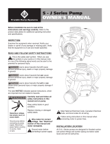
Self Priming Sprinkler Pump
BEFORE YOU START
BEFORE INSTALLING PUMP, BE SURE TO READ
THIS OWNER’S MANUAL CAREFULLY.
REFER TO PRODUCT DATA PLATE(S) FOR
ADDITIONAL OPERATING INSTRUCTIONS AND
SPECIFICATIONS.
• Keep work area clean, well-lit and uncluttered.
• Keep safety labels clean and in good condition.
• Replace missing or damaged safety labels.
• Wear safety glasses while installing or performing
maintenance on pump.
• Adhere to the guidelines of the National Electric Code
(NEC) or Canadian Electric Code (CEC), and any other
state and local codes for ALL electrical installations.
Check with the appropriate agencies or contact a
licensed electrician.
Most water system problems result from improper
installation. It is suggested that you read this
manual carefully before installing your pump. The
“TROUBLESHOOTING SECTION” will assist you in
locating and eliminating the cause of any trouble you
may encounter after installation. Check and make
available all the tools you will need to install your pump.
Required tools may include wrenches, pipe sealant, pipe
fi ttings and nipples, screwdriver, etc.
READ AND FOLLOW SAFETY INSTRUCTIONS
This is the safety alert symbol. When you see
this symbol on your pump or in this manual, look
for one of the following signal words and be alert to the
potential for personal injury:
DANGER
warns about hazards that will cause
serious personal injury, death or major property damage
if ignored.
WARNING
warns about hazards that can cause
serious personal injury, death or major property damage
if ignored.
CAUTION
warns about hazards that will or can
cause minor personal injury or major property damage if
ignored.
NOTICE indicates special instructions, which are
important but not related to hazards.
Carefully read and follow all safety instructions in
this manual and on pump.
HAZARDOUS PRESSURE: Do not run
pump against closed discharge. Release all system
pressure before working on any component.
Do not run pump dry. Fill pump with
water before starting or pump will be damaged.
The motor on this pump is guaranteed by the
manufacturer and in event of failure it must be returned
to an authorized service station for repairs. Motor
warranty is void if repairs aren’t made by an authorized
repair station.
WARNING
WARNING
CAUTION
CAUTION
WARNING
Be sure to have available proper and adequate wiring
material to complete the installation correctly.

1
ELECTRICAL SAFETY
CAUTION
Make sure all ELECTRICAL POWER IS
OFF before connecting any electrical wires.
WARNING
Capacitor voltage may be hazardous.
To discharge motor capacitor, hold insulated handle
screwdriver BY THE HANDLE and short capacitor
terminals together. Do not touch metal screwdriver blade
or capacitor terminals or electrical shock could occur. If
in doubt, consult a qualifi ed electrician.
Wire motor for correct
voltage. See “Electrical
Installation” section of this
manual and motor nameplate.
Ground motor
before connecting to
power supply.
Meet National Electrical
Code (NEC) or Canadian
Electrical Code(CEC) and
local codes for all wiring.
Follow all pump wiring
instructions provided in
this manual.
CAUTION
DO NOT touch an operating motor. The
surface of the motor may be HOT. Allow the motor to
cool for thirty (30) minutes before handling.
GENERAL SAFETY
• Do not allow pump or any system component to
freeze. To do so will void the warranty.
• This pump has been evaluated for pumping
water only. Pumping liquids other than water may
void warranty.
• Periodically inspect pump and system components.
Hazardous voltage.
Can shock, burn, or
cause death.
Ground pump before
connecting to power
supply. Disconnect
power before working
on pump, motor
or tank.
WARNING
INTRODUCTION
You have purchased one of the most user friendly
pumps available. The Turf Boss pumps are made with
high quality materials which are designed to provide
you with years of reliable service. Lawn sprinklers are
designed to maximize output fl ow, while still maintaining
the ability to draw water from a source up to 25 feet
below the pump. All mechanical parts, motor, impeller,
electrical controls, etc., are above ground within easy
reach. If service is ever necessary, simple hand tools will
do the job. This lawn sprinkler pump installs easily and
quickly without the need for special tools or pump rigs.
You can install it yourself provided you follow closely the
instructions contained in this manual.
INSPECT YOUR SHIPMENT
All Turf Boss lawn sprinkler pumps are carefully tested,
inspected, and packaged to insure their arrival in perfect
condition. When the pump is received, examine it closely
to make sure there is no damage or broken parts that
may have occurred in shipping. If damage is evident,
report this immediately to your shipping carrier and
dealer. This shipping carrier assumes full responsibility
for the shipment’s safe arrival. Any claim for damage to
the shipment, either visible or concealed, must be made
through the shipping carrier fi rst.

2
Following are three well and water source
applications for the Turf Boss sprinkler pump.
Wells may differ slightly but the application is
essentially the same.
Single Shallow Well (Figure 1)
The single shallow well is typically a drilled well with
a 4" or 6" steel or plastic casing running vertically
into the ground. The surface of the water should not
exceed 25 feet in depth.
Connect the foot valve to the
fi rst length of suction pipe and
lower into well. Add pipe sections
as needed, securing them using
one of the sealing methods
previously mentioned. The foot
valve should be AT LEAST fi ve
feet below the surface of the water
to allow for water draw down.
Seal the top of the 4" or 6" well
casing with a well seal to prevent
debris from falling into the well.
PRE-INSTALLATION CHECK
• Pump must not be more than 25 feet above the
surface of the water.
• Use as few elbows and fi ttings as possible to
reduce friction and maximize fl ow.
• Be sure pipe, fi ttings, and foot valve are clean
and free of debris.
• There should be no air pockets or leaks in the
suction pipe.
• Tefl on tape should be used to seal threaded pipe
connections.
INSTALLATION TIPS
1-1/2" MINIMU
RIDGED PVC
P
1-1/2" MINIMUM
PVC ADAPTER
1-1/2" MINIMUM
FOOT VALVE
1-1/2" PVC
ELBOW
WELL
SEAL
Figure 3
• Wrap all threaded male pipe
ends and fi ttings with tefl on tape.
This will ensure a good seal around
all pipe connections.
• PVC Pipe Connections: Use
PVC pipe primer on all glue joints
before applying PVC cement.
After applying PVC cement to both
surfaces to be glued, connect pipe
and fi tting, turn pipe one-quarter
turn and hold for 30 seconds. This
will ensure a positive cementing of
all joints.
INSTALLATION
LOCATION OF PUMP
Decide on an area for the pump installation that
is suitable based on the enclosure rating of the
electric pump motor. All Turf Boss pumps are
UL778 approved and will be marked “ACCEPTABLE
FOR OUTDOOR or INDOOR USE.”
• INDOOR PUMP INSTALLATION OPTION:
Choose a clean, well-ventilated, weatherproof location
that affords protection from freezing, fl ooding, and
excessive heat. In addition, it should provide access
for servicing and allow convenient draining of the
pump and service pipes. A prepared foundation is not
essential, provided the surface is hard and level. It
can be located in the basement or utility room of your
house, at the well or between the point of use and
the well.
• OUTDOOR PUMP INSTALLATION OPTION:
When installing outside of the house, the pump should
be protected by a pump house with auxiliary heat to
prevent possible freezing.
Choose a clean location best suited for the water
system. A prepared foundation is not essential,
provided the surface is hard and level. It should provide
access for servicing and allow convenient draining of
the pump and service pipes. When installing outside
of the house, the pump and piping system must be
drained completely of water to prevent possible freezing
when weather dictates.
Decide how to seal the well from surface contamination
as required by local authorities. The most common
device for this purpose is the SANITARY WELL SEAL.
If the pipes from the well have to be kept below the
frost line, either bury the wellhead or use a PITLESS
ADAPTER that leaves the wellhead exposed for
servicing while providing sealed openings in the well
casing below the frost line.
Figure 1

3
Lake Or Pond Installation (Figure 3)
Using a surface water source such as a lake or pond is
similar to using a single shallow well. The suction pipe
is placed in the water source and leads back to the
pump. This application may require a long horizontal
distance between water source and pump.
The suction pipe size should increase by one
size to minimize pressure loss caused by friction from
pipe distance.
Place a foot valve at the end of the suction pipe to
protect the pump from debris.
1-1/2" MINIMUM
RIDGED PVC PIPE
1-1/2" MINIMUM
PVC ADAPTER
1-1/2" MINIMUM
FOOT VALVE
Figure 3
PLUMBING
Bolt the pump to a level, solid foundation, if possible.
Position the pump with the suction port facing the
water source pipe(s). Avoid 90º angles whenever
possible and minimize turns when connecting pump
to your water source. Install the pump as close to the
water source as possible. This will help reduce friction
and maximize water pressure.
HORIZONTAL OFFSET SUCTION PIPING
When the pump is offset from the well, the horizontal
offset suction piping may have to be increased in
diameter to reduce friction loss. The friction loss in a
system increases:
1.) As the fl ow rate increases
2.) As the piping size decreases
Consult included Turf Boss performance tables
(Appendix III) and friction loss tables (Appendix IV)
to determine the amount of head lost for a given
application. Pipes from the well to the pump should
slope upward (about 1” of rise for every 30” of run).
DISCHARGE PIPE SIZES FOR INSTALLATION
When the pump is located at a distance from points of
water use, it is necessary to increase the discharge pipe
size in order to reduce friction loss. The friction loss in a
system increases:
1.) As the fl ow rate increases
2.) As the piping size decreases
Consult included Turf Boss performance tables
(Appendix III) and friction loss tables (Appendix IV)
to determine the amount of head lost for a given
application.
Figure 2
Multi-shallow Well Points (Figure 2)
The multi-point shallow well confi guration consists of
two or more wells as a water supply. The wells should
be at least fi ve feet apart. The wells may be spaced
as a straight line (two or more wells), a triangle (three
wells), or a square (four wells).
Install a check valve or a fi ne screen well point
on each well to ensure the pump maintains prime.
The fl ow arrow on a check valve must point toward
the pump.

4
1-1/2”
GALVANIZED
PIPE
WELL POINT
CHECK
VALVE
1-1/2” RIDGED
PVC PIPE
1-1/2 RIDGED
PVC PIPE
1-1/2” PVC
ADAPTER
1-1/2” FOOT
VALVE
1-1/2” PVC
ELBOW
WELL
SEAL
WELL POINT
INSTALLATION
1-1/2” DISCHARGE PORT
1-1/2”
GALVANIZED
PIPE
WELL POINT
1-1/2” PVC
ELBOW
MULTIPLE WELL
POINT INSTALLATION
CHECK
VALVE
TO
PUMP
TO SPRINKLE
R SYSTEM
PRIMING PORT
1-1/2” SUCTION PORT
DRAIN PLUG
1-1/2” PVC
ELBOW
A. Suction Port Connection (Figure 4)
Step 1:
Attach the foot valve or well point to pipe assembly
and lower pipe and foot valve until it is at least fi ve
feet below the water level. If you are using a well,
temporarily clamp the pipe to the well casing to
prevent the pipe from sliding into the well. If well is
in a 4" or 6" casing, use a well seal at the surface.
Never use a suction pipe size smaller than the size
of the suction port on the pump.
Step 2:
Connect the necessary elbows, fi ttings, check
valves, and pipe from the water to the pump suction
port on front of pump. When using PVC, pre-
assemble pipe and fi ttings to the pump BEFORE
applying PVC cement to ensure proper cuts and
inventory. Use tefl on tape on all male threads,
wrapping clockwise (when facing pipe) 1 to 2 layers
thick. Tighten all threaded pipe fi ttings until snug.
DO NOT OVER TIGHTEN PIPE AND FITTINGS!!
Tighten joints hand tight plus 1/2 turn with
pipe wrench.
B. Discharge Port Connections (Figure 5)
Step 1:
Thread male adapter or pipe nipple into discharge port
on top of pump. (Use tefl on tape on thread)
Step 2:
Connect pipe between the sprinkler manifold and
the pump discharge. Discharge pipe size should
increase with long pipe runs. Discharge pipe size
may equal discharge port size for distances up to
100'. Increase discharge pipe size by one size for
distances of 100' to 300'. For 300' to 600', increase
pipe size by two sizes. This will reduce pressure
loss caused by friction.
Step 3:
Tighten all threaded pipe connections with pipe wrench
until snug. Do not over tighten.
PRIMING PORT
1-1/2" SUCTION PORT
DRAIN PLUG
1-1/2" DISCHARGE PORT
Figure 4
Figure 5

5
INSTALLATION RECORDS
To keep an accurate record of your installation, be
sure to fi ll out the data below:
ELECTRICAL INSTALLATION
WARNING
Hazardous
voltage can shock, burn or
cause death.
CAUTION
If you are
not sure of proper electrical
connections, consult a licensed
electrician.
CAUTION
Improper wiring
can result in permanent damage
to the motor. All electrical wiring
should meet the local electrical
code.
NOTICE
READ AND FOLLOW ALL INSTRUCTIONS!
• Pump connection must comply with National
Electric Code (NEC) or Canadian Electric Code
(CEC), and all applicable local codes.
• All dual voltage units come factory preset for
230 volts. (Figure 3)
• Disconnect power at electrical panel before
making any electrical connections.
• Supply voltage must be +/- 10% of motor
nameplate voltage. Low or high voltage can
damage the motor and will void the warranty.
• If possible, connect pump to dedicated branch
circuit with no other appliances on it.
• Do not operate pump unless pump is grounded
WARNING
Date of Installation:
Model No.
Depth of Well (ft):
Depth to Water (ft):
Inside diameter of Well:
Suction Pipe Size:
Suction pipe length (ft):
Discharge pipe length (ft):
Motor:
HP:
Volts:
Wire gauge size:
DUAL VOLTAGE ADJUSTMENT
NOTE:
To change the motor voltage(Figure 6) unplug
the dual voltage connector on the motor and reconnect
it in the position required to match the available
electrical system. The motor can be set for 115 volts
or 230 volts, except for 2 hp modles which are 230
volts only. The voltage setting of the motor can be
determined by looking at the alignment of the arrow
on the plug and the arrow on the motor terminal board
(located under the motor’s end cover). Any questions
as to which voltage setting is required for proper motor
and pump operation in your system should be directed
to an electrical professional. The factory preset is
230 volts.
Wiring Installation
NOTICE: Check motor terminal cover or nameplate
for wiring instructions. The essential pump motor facts
are as follows:
1.) 3450 RPM
2.) Single Phase
3.) Dual Voltage, 115/230 on 1 and 1-1/2 HP; 230 V
only on 2 HP motors.
4.) 1/2, 3/4, 1, and 1-1/2 Horsepower motors are
wired for 230 volts as a factory standard.
Step 1:
Remove motor access cover at back of motor.
Step 2:
Feed the grounding wire (green or bare copper)
through the electrical conduit port in the side of the
motor. First connect the ground wire then connect
the power supply wires. Attach the grounding wire
to the motor ground screw (green). Secure wires to
prevent electrical shorts.
230V
115V
230V
115V
115V 230V
Figure 6

6
Step 3:
Connect the incoming power supply wires to the
motor terminal.
Step 4:
Replace and secure motor cover.
NOTE: Single phase motors rotate counterclockwise
only (when facing suction port) and cannot
be reversed.
MOTOR
NOTICE: A motor operating under normal
conditions maintains its rated performance,
assuming a clean, dry motor with proper ventilation.
A dirty motor, or one “protected” by a burlap or
plastic bag, will overheat.
PRIMING AND START UP
G
NEVER run pump dry. Fill pump with
water before starting pump. Operating pump dry may
cause damage to pump and will void warranty.
NEVER run pump against a closed
discharge. This may cause hazardous pressure and
risk of explosion.
Step 1 (Figure 7):
Remove priming port plug from pump.
Step 2:
Open discharge valves and any hoses on
discharge side of pump.
Step 3:
Fill pump with water through the priming port on
top of pump. Allow trapped air to escape for a few
minutes, then add more water until full.
PRIMING PORT
1-1/2" SUCTION PORT
DRAIN PLUG
1-1/2" DISCHARGE PORT
WA
RNIN
G
WARNING
WARNIN
G
WARNING
Step 4:
Replace priming port plug and tighten with wrench,
using tefl on tape on pipe threads.
Step 5:
Start the pump. A properly primed pump should
discharge water without air at a consistent
pressure. If the pump does not produce water after
fi ve minutes, stop the pump, release all pressure,
remove priming port plug, add more water, replace
plug, and try again. (Make sure that a foot valve
is properly installed on the suction pipe. See
"Suction port connection". Figure 4)
MAINTENANCE
Failure to disconnect
electrical power before attempting
maintenance can cause shock, burns,
or death.
Before disconnecting
pump, be sure fuse box leads are
disconnected or power is turned off.
After reassembling the pump, refer to
priming instructions before running.
HAZARDOUS PRESSURE!
-Do not run pump against
closed discharge.
-Release all pressure on system
before working on any component.
A. Draining (Figure 8)
The pump should be drained if it is in danger of
freezing, if it will be out of service for an extended
period of time, or if it requires service.
To drain pump, disconnect power source,
remove priming port plug from pump case, remove
drain plug (below suction port), and drain system.
Replace drain plug.
WARNING
WARNING
WARNING
WARNING
Figure 7

7
NOTICE: While this will drain the pump, it will
not necessarily drain all other parts of the piping
system. If there are any concerns with the proper
procedure or necessity of draining the suction
plumbing, contact your contractor.
B. Pump Disassembly (Appendix I & Figure 9)
In order to access the internal components of the
pump, review the exploded diagram of the pump
assembly as shown on the repair parts page(Appendix
I). Drain the pump as described above and then
remove the four bolts that hold the pump case to the
motor bracket. This will allow the motor and hydraulic
sub-assembly to be removed from the case without
disturbing the plumbing. Locate and inspect the
diaphragm and grommet which are internal water
seals. Make sure they are in good condition and are
working properly. To remove the diffuser, loosen
the 3 bolts that attach it to the motor bracket. This
will expose the impeller and eye-seal. Remove the
eye-seal and then, in order to remove the impeller,
securely hold the motor shaft with a pair of vice grips
to prevent any unwanted rotation. Turn the impeller
counter-clockwise (when facing impeller) to remove
and this will reveal the mechanical shaft seal. This
seal can then be removed from the motor shaft for
inspection. The motor bracket can be removed from
the motor by removing the 4 bolts on the backside
of the motor bracket. To remove the ceramic shaft
seal, press gently from the backside on the ceramic
and it will fall out easily. Inspect, clean or replace
parts as needed.
C. Pump Assembly
Reassemble unit by fi rst pressing the ceramic seal into
the seal plate. Use rubbing alcohol as a lubricant. Do
not use an oil, vaseline or grease as this will damage
the sealing surfaces of the shaft seal during operation.
Next, install the motor bracket onto the motor using
the four bolts. Tighten the bolts in a diagonal pattern
to insure a proper fi t. Place the shaft seal on the motor
shaft and then install the impeller and eye-seal. The
diffuser is positioned by three bolts that can only be
installed when the diffuser is oriented properly (Figure
9). Position the diaphragm on the diffuser suction eye.
(as shown in Figure 9). The grommet will slide over
the diffuser eye on top of the diaphragm. Lift the motor
assembly up into the pump case and attach it using
the 4 bolts. When seating the pump case against the
motor bracket, the diaphragm should be captivated
between them around the entire perimeter. This allows
the diaphragm to serve as a water seal between the
two cast iron parts. If the diaphragm is not positioned
correctly the unit will leak once the case is fi lled with
water. Tighten all bolts to 185 in-lbs in a diagonal
pattern to insure proper seating of all components.
Drain Plug
Priming Port
Diffuser
Motor
Bracket
Diffuser Bolt
Diffuser Bolt
Grommet
Diaphragm
Figure 8
Figure 9

8
PARTS FOR TURF BOSS
SELF-PRIMING SPRINKLER PUMP
Figure
Number
Description
Kit Grouping
Identifi er*
Repair Part Order Codes by Model Number
TB1CI TB15CI TB2CI
1
Plug Kits A 305390901
2
Pump Case B 305491901
3
Grommet
C 305392901
G 305396901 305396902 305396903
4
Diaphragm
C 305392901
G 305396901 305396902 305396903
5
Fastener Kit* D 305393901
6
Diffuser
E 305394901 305394902 305394903
G 305396901 305396902 305396903
7
Wear Ring
E 305394901 305394902 305394903
G 305396901 305396902 305396903
8
Impeller
E 305394901 305394902 305394903
G 305396901 305396902 305396903
9
Mechanical Seal
F 305395901
G 305396901 305396902 305396903
10
Motor Bracket H 305397901
11
Motor I 305398901 305398902 305398903
12
Base Assembly J 305399901
* Items with like identifi ers are sold/packaged together
** Fastener kits (5D) is a complete set of the hardware used to assemble the Turf Boss. As a convenience all other
repair kits contain the fasteners needed for the reassembly of its components.
11 I
5D
5D
10H
9F,G
5D
5D
8E,G
7E,G
6E,G
5D
5D
4C,G
3C,G
1A
2B
5D
5D
1A
12J
APPENDIX I

9
A. Pump does not deliver water or pressure
Cause: The pump is not full of water.
Remedy: Stop the pump, fi ll it with water, check all
pipe connections to make sure there are no air leaks
and try again.
B. Low pressure
Cause: The motor is not up to speed.
Remedy: Check for proper voltage and tight wiring
connections.
Cause: The impeller is partially plugged.
Remedy: Check impeller for rocks or debris. Refer
to disassembly instruction for getting to impeller.
Cause: Air is leaking into suction line.
Remedy: Check suction line connections.
C. Low capacity
Cause: Your water level is deeper than 25 feet.
Remedy: Pump can’t pump below 25 feet. Call your
Franklin Pump Systems dealer.
Cause: You are using too long a pipe from the
water to the pump.
Remedy: You should use a larger diameter pipe.
Cause: You have a plugged impeller.
Remedy: Check impeller. Refer to disassembly
instructions above.
Cause: The pipe from the pump to the water is
partially plugged.
Remedy: Check pipe.
D. Motor overheats
Cause: Improper voltage or wiring connections.
Remedy: Check to see if your voltage is the same
as indicated on the motor name on dataplate. Be
sure all wiring connections are tight.
Cause: Improper ventilation for the motor.
Remedy: Check to see if motor is clean and
properly vented.
E. Motor will not start
Cause: Open switches, blown fuses or loose
connections.
Remedy: Check switches, fuses, and connections.
Cause: Improper connections to motor.
Remedy: Make sure connections are tight.
F. Air logging (excessive air in pipe)
Cause: Air leaks in pipe
Remedy: Check connections.
Cause: Water drops below the end of the pipe.
Remedy: Pump is out-producing well. Tighten down
control valve gradually until pump starts operating
properly.
G. Gravelly noises inside pump (cavitation)
Cause: Pump running over capacity
(NPSHR exceeds NPSHA)
Remedy: Call your Franklin Pump Systems dealer.
Cause: Suction pipe is too small or length of pipe is
too long.
Remedy: Use a larger diameter pipe.
Cause: End of suction pipe is in mud or sand.
Remedy: Raise end of suction pipe or clean
out well.
APPENDIX II - TROUBLESHOOTING

10
0 1020304050607080
0
0
12345
2 4 6 8 10 12 14 16 18
10
000
30
40
50
60
70
80
90
20
100
110
METERS
PSI
FEET
GPM
LPS
M PH
3
5
5
10
10
15
20
15
25
30
35
40
45
30
25
20
130
140
120
50
55
60
40
35
2 HP
1.5 HP
1 HP
APPENDIX III - PERFORMANCE CURVE

11
APPENDIX IV - FRICTION LOSS TABLES
1”
Schedule 40 pipe 1.049 in. i.d. / Type L Copper tube 1.025 in. i.d.
GPM
Velocity
Ft/S
Friction Loss
Ft Hd./100’ of pipe
Velocity
Ft/S
Ft Hd./
100’ Pipe
Fric. Loss
C=130
Steel
C=100
PVC
C=140
2.0 0.74 0.60 0.32 .078 0.41
3.0 1.11 1.26 0.68 1.17 0.87
4.0 1.49 2.14 1.15 1.56 1.48
5.0 1.86 3.24 1.75 1.95 2.23
6.0 2.23 4.54 2.45 2.34 3.13
8.0 2.97 7.73 4.16 3.11 5.35
10 3.71 11.7 6.31 3.89 8.08
12 4.46 16.4 8.85 4.67 11.3
14 5.20 21.8 11.8 5.45 15.0
16 5.94 27.9 15.1 6.22 19.2
18 6.68 34.7 18.7 7.00 23.9
20 7.43 42.1 22.8 7.78 29.0
25 9.29 63.6 34.6 9.74 43.9
30 11.1 89.2 48.1 11.7 61.4
40 14.9 152 82.0 15.5 105
1.5”
Schedule 40 pipe 1.610 in. i.d. / Type L Copper tube 1.505 in. i.d.
GPM
Velocity
Ft/S
Friction Loss
Ft Hd./100’ of pipe
Velocity
Ft/S
Ft Hd./
100’ Pipe
Fric. Loss
C=130
Steel
C=100
PVC
C=140
6.0 0.95 0.57 0.31 1.08 0.49
8.0 1.26 0.96 0.52 1.44 0.82
10 1.58 1.45 0.79 1.80 1.24
12 1.89 2.04 1.10 2.16 1.73
15 2.36 2.95 1.59 2.70 2.62
20 3.15 5.24 2.83 3.60 4.46
25 3.94 7.90 4.26 4.51 6.74
30 4.73 11.1 6.00 5.41 9.44
40 6.30 18.9 10.2 7.21 16.1
50 7.88 28.5 15.4 9.01 24.3
60 9.46 40.0 21.6 10.8 34.1
70 11.0 53.2 28.7 12.6 45.5
80 12.6 68.1 36.8 14.4 58.1
90 14.2 84.7 45.7 16.2 72.1
100 15.8 103 56.6 18.0 87.7
2.5”
Schedule 40 pipe 2.469 in. i.d. / Type L Copper tube 2.465 in. i.d.
GPM
Velocity
Ft/S
Friction Loss
Ft Hd./100’ of pipe
Velocity
Ft /S
Ft Hd./
100’ Pipe
Fric. Loss
C=130
Steel
C=100
PVC
C=140
20 1.21 0.66 0.35 1.34 0.40
30 2.01 1.39 0.75 2.02 0.85
40 2.68 2.36 1.27 2.69 1.46
50 3.35 3.56 1.92 3.36 2.20
60 4.02 4.99 2.69 4.03 3.08
70 4.69 6.64 3.58 4.70 4.11
80 5.36 8.50 4.59 5.37 5.25
90 6.03 10.6 5.72 6.04 6.52
100 6.70 12.8 6.90 6.71 7.94
110 7.37 15.3 8.22 7.38 9.44
130 8.71 20.9 11.3 8.73 12.9
150 10.0 27.3 14.7 10.1 16.8
200 13.4 46.3 25.0 13.4 28.6
250 16.8 81.7 44.1 16.8 43.4
300 20.1 98.1 52.9 20.1 61.1
1¼”
Schedule 40 pipe 1.380 in. i.d. / Type L Copper tube 1.265 in. i.d.
GPM
Velocity
Ft/S
Friction Loss
Ft Hd./100’ of pipe
Velocity
Ft /S
Ft Hd./
100’ Pipe
Fric. Loss
C=130
Steel
C=100
PVC
C=140
4.0 0.86 0.56 0.30 1.02 0.52
6.0 1.29 1.20 0.65 1.53 1.12
8.0 1.72 2.04 1.10 2.04 1.92
10 2.15 3.08 1.67 2.55 2.90
12 2.57 4.31 2.33 3.06 4.04
14 2.00 5.73 3.10 3.57 5.35
16 3.43 7.34 3.96 4.08 6.85
18 3.86 9.13 4.93 4.59 8.52
20 4.29 11.1 6.00 5.10 10.4
25 5.36 16.8 9.06 6.38 15.7
30 6.43 23.5 12.7 7.65 22.1
40 8.58 40.0 21.6 10.2 37.6
50 10.7 60.4 32.6 12.8 56.7
60 12.9 84.7 45.6 15.3 79.5
80 17.2 144 77.9 20.4 136
2”
Schedule 40 pipe 2.067 in. i.d. / Type L Copper tube 1.985 in. i.d.
GPM
Velocity
Ft/S
Friction Loss
Ft Hd./100’ of pipe
Velocity
Ft/S
Ft Hd./
100’ Pipe
Fric. Loss
C=130
Steel
C=100
PVC
C=140
10 0.96 0.43 0.23 1.07 0.35
15 1.44 0.92 0.50 1.60 .075
20 1.91 1.55 0.84 2.13 1.24
25 2.39 2.35 1.27 2.66 1.87
30 2.87 3.29 1.78 3.19 2.62
40 3.82 5.60 3.03 4.26 4.48
50 4.78 8.46 4.57 5.32 6.76
60 5.74 11.9 6.44 6.39 9.47
70 6.69 15.8 8.53 7.45 12.6
80 7.65 20.2 10.9 8.52 16.2
90 8.61 25.1 13.6 9.58 20.0
100 9.56 30.5 16.5 10.7 24.4
120 11.5 42.7 23.1 12.8 34.1
150 14.3 64.7 35.0 16.0 51.6
200 19.1 110 59.4 21.3 87.8
Note: Chart shows friction loss per 100’ of pipe. To convert to friction loss per foot, move decimal point 2 places to the left.

106258101 Rev. 0 3/08
400 E. Spring Street
Bluffton, IN 46714
Tel: 260-824-2900
Fax: 260-824-2909
www.franklin-electric.com
U.S. LIMITED WARRANTY*
Franklin Electric Co., Inc.
Franklin Electric Co., Inc. warrants its new products to be free of defects in material and workmanship for a period
of 1 year from date of installation or 2 years from date of manufacture, whichever comes fi rst, WHEN installed in clean,
potable water applications. Warranty does not cover applications pumping saltwater or other corrosive liquids. Consult
and adhere to local codes for all applications. Franklin Electric Co., Inc. also provides additional warranty coverage on
specifi c products as specifi ed herein.
Franklin Electric’s warranty obligation with regard to equipment not of its own manufacture is limited to the warranty
actually extended to Franklin Electric by its suppliers.
This warranty extends only to the original retail purchaser and only during the time in which the original retail
purchaser occupies the site where the product was originally installed.
Requests for service under this warranty shall be made by contacting the installing Franklin Electric dealer (point
of purchase) as soon as possible after the discovery of any alleged defect. Franklin Electric will subsequently take
corrective action as promptly as reasonably possible.
Franklin Electric at its discretion may replace or repair any product that fails under this warranty after inspection by
an authorized company representative or after Franklin Electric has received the product at our factory. Replacement
or repair cannot be made until after the product is inspected. All charges or expenses for freight to and from the factory,
removal and reinstallation of the product, or installation of a replacement product are the responsibility of the purchaser.
THIS WARRANTY SUPERSEDES ANY WARRANTY NOT DATED OR BEARING AN EARLIER DATE. ANY
IMPLIED WARRANTIES WHICH THE PURCHASER MAY HAVE, INCLUDING MERCHANT ABILITY AND FITNESS
FOR A PARTICULAR PURPOSE, SHALL NOT EXTEND BEYOND THE APPLICABLE WARRANTY PERIOD.
Some states do not allow limitations on how long an implied warranty lasts, so the above limitation may not
apply to you. IN NO EVENT SHALL FRANKLIN ELECTRIC BE LIABLE FOR INCIDENTAL OR CONSEQUENTIAL
DAMAGES. Some states do not allow the exclusion or limitation of incidental or consequential damages, so
the above may not apply to you.
This warranty does not apply to any product which has been subjected to negligence, alteration, accident, abuse,
misuse, improper installation, vandalism, civil disturbances, or acts of God. The only warranties authorized by Franklin
Electric are those set forth herein. Franklin Electric does not authorize other persons to extend any warranties with
respect to its products, nor will Franklin Electric assume liability for any unauthorized warranties made in connection
with the sale of its products.
THIS WARRANTY GIVES YOU SPECIFIC LEGAL RIGHTS, AND YOU MAY ALSO HAVE OTHER RIGHTS WHICH
MAY VARY FROM STATE TO STATE.
* Contact Franklin Electric Co., Inc. Export Division for International Warranty.

24
0 1020304050607080
0
0
12345
2 4 6 8 10 12 14 16 18
10
000
30
40
50
60
70
80
90
20
100
110
METROS
PSI
PIES
GPM
l./seg.
M PH
3
5
5
10
10
15
20
15
25
30
35
40
45
30
25
20
130
140
120
50
55
60
40
35
2 HP
1.5 HP
1 HP
APÉNDICE III - CURVA DE DESEMPEÑO

38
0 1020304050607080
0
0
12345
2 4 6 8 10 12 14 16 18
10
000
30
40
50
60
70
80
90
20
100
110
MÈTRES
PSI
PIEDS
GPM
LPS
M PH
3
5
5
10
10
15
20
15
25
30
35
40
45
30
25
20
130
140
120
50
55
60
40
35
2 HP
1.5 HP
1 HP
ANNEXE III - COURBE DE RENDEMENT
/