Page is loading ...

2
ETL-ES-Techno-WH14
1. Installation work and electrical wiring must be done by qualified person(s) in accordance with all applicable codes and standards (ANSI/NFPA 70-1999), including fire-rated construction.
2. Use this unit only in the manner intended by the manufacturer. If you have any questions contact the manufacturer.
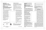
3. After making the wire connections, gently push connections into outlet box with wire nuts pointing up. The wires should be spread apart with the grounded conductor and the equipment-grounding conductor on
one side of the outlet box and ungrounded conductor on the other side of the outlet box.
4. Before you begin installing the fan, switch power off at service panel and lock service disconnecting means to prevent power from being switched on accidentally. When the service disconnecting means cannot be
locked, securely fasten a prominent warning device, such as a tag, to the service panel.
5. Be cautious! Read all instructions and safety information before installing your new fan. Review the accompanying assembly diagrams.
6. When cutting or drilling into wall or ceiling, do not damage electrical wiring and other hidden utilities.
7. Make sure the installation site you choose allows the fan blades to rotate without any obstructions. Allow a minimum clearance of 7 feet from the floor to the trailing edge of the blade.
8. To reduce the risk of fire, electric shock, or personal injury, this fan must be mounted to an outlet box marked suitable for fan support, and use the mounting screws provided with the outlet box. (Mounting must
support at least 35 lbs.)
9. WARNING! Do not bend blade holders during installation to motor, balancing or during cleaning. Do not insert foreign object between rotating blades.
10. Attach the mounting bracket using only the hardware supplied with the outlet box. Fan is only to be mounted to an outlet box marked “Acceptable for Fan Support”.
11. WARNING! To reduce the risk of fire or electric shock, do not use this fan with any solid state fan speed control device, or variable speed control.
12. If this unit is to be installed over a tub or shower, it must be marked as appropriate for the application.
13. NEVER place a switch where it can be reached from a tub or shower.
14. The combustion airflow needed for safe operation of fuel-burn ing equipment may be affected by this unit’s operation. Follow the heating equipment manufacturer’s guideline safety standards such as those
published by the National Fire Protection Association (NFPA), and the American Society for Heating, Refrigeration and Air Conditioning Engineers (ASHRAE) and the local code authorities.
15. Before servicing or cleaning unit, Switch power off at Service panel and lock service disconnecting means to prevent power from being switched on accidentally. When the service disconnecting means cannot be
locked, securely fasten a prominent warning device, such as a tag, to the service panel.
16. All set screws must be checked and re-tightened where necessary before installation.
17. The appliance is not intended for use by young children or infirm persons without supervised. Young children should be supervised to ensure that they do not play with the appliance.
18. The LED Luminaire contains no UV.
TOOLS REQUIRED
Phillips Screwdriver Wire Cutters Pliers Step Ladder
SAFETY TIPS
OBSERVE THE FOLLOWING: READ AND SAVE THESE INSTRUCTIONS
WARNING: TO REDUCE THE RISK OF FIRE, ELECTRIC SHOCK, OR PERSONAL INJURY, MOUNT TO OUTLET BOX MARKED 'ACCEPTABLE FOR FAN SUPPORT OF 15.9 KG (35 LBS) OR LESS'
AND USE MOUNTING SCREWS PROVIDED WITH THE OUTLET BOX AND/OR SUPPORT DIRECTLY FROM BUILDING STRUCTURE. MOST OUTLET BOXES COMMONLY USED FOR THE
SUPPORT OF LUMINARIES ARE NOT ACCEPTABLE FOR FAN SUPPORT AND MAY NEED TO BE REPLACED. CONSULT A QUALIFIED ELECTRICIAN IF IN DOUBT.

4
ETL-ES-Techno-WH14
FEATURES
CARACTERÍSTICAS
VAULTED CEILING
INSTALLATION
NSTALACIÓN PARA
CIELORRASOS ABOVEDADOS
DOWNROD
INSTALLATION
INSTALACIÓN CON
VARILLA VERTICAL
May require a longer downrod
(sold separately)
Podría requerir una varilla vertical más larga
(se vende por separado)
For normal ceilings
Para cielorrasos normales
Note: For pitched ceiling installation, please
refer to westinghouselighting.com for specially
designed canopy kit options.
Nota: Para instalación en cielo rasos inclinados,
visite westinghouselighting.com para obtener
información.

6
ETL-ES-Techno-WH14
Instale el soporte de montaje a la caja de embutir del cielorraso con la
tornillería suministrada con la caja de embutir.
MOUNTING BRACKET INSTALLATION
INSTALACIÓN CON SOPORTE DE MONTAJE
3
4
MOUNTING OPTIONS
OPCIONES DE MONTAJE
Choose a MOUNTING OPTION
Elija una OPCIÓN DE MONTAJE
NORMAL DOWNROD OPTION
If installing downrod supplied with fan, proceed to page 7, step#5.
OPCIÓN CON VARILLA VERTICAL PARA CIELORRASO NORMAL
Si instala la varilla vertical incluida con el ventilador,
proceda a la página 7, paso 5.
EXTENDED DOWNROD OPTION
If installing with longer downrod than supplied with fan, proceed to page 9, step#8.
OPCIÓN CON VARILLA VERTICAL MÁS LARGA
Si instala una varilla vertical más larga que la que se incluye con el
ventilador, proceda a la página 9, paso 8.
Install mounting bracket to outlet box in ceiling using the screws and
washers provided with the outlet box.

7
ETL-ES-Techno-WH14
6
Place downrod assembly into canopy (1), canopy cover ring (2) and coupling cover (3).
Feed motor wires through the downrod assembly (4).
Coloque el conjunto de la varilla vertical (1) dentro del dosel (1), el anillo de la cubierta
del dosel (2) y la cubierta del acoplamiento (3). Pase los cables del motor a través del
conjunto de la varilla vertical (4).
2
1
3
4
Quite el pasador tipo prensa (1) desde el pasador transversal (2) de la vara (3).
5
Remove clamp pin (1) and cross pin (2) from downrod (3).
1
2
3
NORMAL DOWNROD OPTION
OPCIÓN CON VARILLA VERTICAL PARA CIELORRASO NORMAL

9
ETL-ES-Techno-WH14
Loosen downrod ball (1) from downrod (2) by removing set screw (3).
Afloje la esfera de la varilla vertical (1) de la varilla vertical (2)
quitando el tornillo (3).
8
2
3
1
EXTENDED DOWNROD OPTION
OPCIÓN CON VARILLA VERTICAL MÁS LARGA
Slide downrod ball (1) off of downrod and remove pin (2).
Deslice la esfera de la varilla vertical (1) hasta separarla de la
varilla vertical y quite el pasador (2).
9
2
1

10
ETL-ES-Techno-WH14
Re-install pin into extended downrod, and slide downrod ball up to the top of the downrod. Re-install set screw to secure ball to downrod. Note: Some extended downrods have
a pre-drilled set-screw hole. If a pre-drilled hole is present in the extended downrod, tighten the set screw into the pre-drilled hole in the extended downrod. If no pre-drilled hole
exists in the extended downrod, tighten the set screw against the downrod to secure the downrod ball. PROCEED TO PAGE 7, STEP#5.
Vuelva a instalar el pasador en la varilla vertical más larga y deslice la esfera de la varilla hasta el extremo superior de la misma. Vuelva a insertar el tornillo de fijación para asegurar
la esfera a la varilla vertical. Nota: Algunas varillas verticales más largas tienen un agujero previamente perforado para el tornillo. Si la varilla vertical más larga tiene un agujero
previamente perforado, ajuste el tornillo en el agujeropreviamente perforado de la varilla vertical más larga. Si la varilla vertical más larga no tiene un agujero
previamente perforado, ajuste el tornillo sobre la varilla vertical para asegurar la esfera de la misma. PASEZ À LA PAGE 7, ÉTA PE 5.
EXTENDED DOWNROD OPTION
OPCIÓN CON VARILLA VERTICAL MÁS LARGA
10

11
ETL-ES-Techno-WH14
11
BLADE INSTALLATION
INSTALACIÓN DE LAS PALETAS
2
4
4
3
3
1
Attach blades (1) to the ywheel (2) using the blade bracket screws (3) and washers (4).
Fije las paletas (1) a
la rueda
(2) con los tornillos correspondientes (3) y las arandelas (4).

12
ETL-ES-Techno-WH14
12
BLADE INSTALLATION
INSTALACIÓN DE LAS PALETAS
Place fan body with light xture pointing upward. Attach the fan blades onto the motor, line up the holes in the blades with the holes in the motor ywheel (marked A-A,
B-B. C-C), secure the blades to the ywheel with motor screws provided.
Coloque el ventilador con el artefacto luminoso apuntando hacia arriba. Fije las paletas del ventilador al motor, alinee los oricios de las paletas con los oricios de la
rueda del motor (marcados A-A, B-B, C-C). Asegure las paletas a la rueda con los tornillos para el motor provistos.

15
ETL-ES-Techno-WH14
WIRING OPTIONS
OPCIÓN DE CABLEADO
16
Once wiring step has been completed, slide the wired remote receiver in between the
mounting bracket and the top of the downrod ball for downrod fans.
Para los ventiladores con vara de extensión, al terminar la instalación de los alambres,
deslice el receptor remoto alámbrico entre el soporte de montaje y la parte superior de
la esfera de la vara.
15
Make wiring connections from the house and the motor to the remote receiver as shown
above. Connect using wire nuts (provided).
Haga las conexiones de cableado del alojamiento y el motor al receptor remoto como se
indica más arriba. Utilice las tuercas para cables incluidas.

16
ETL-ES-Techno-WH14
SECURE TO CEILING
ASEGURE EL VENTILADOR AL CIELORRASO
Loosen the 2 screws on the bottom of mounting bracket. (do not remove) Raise the canopy up and align the keyholes on the bottom of the canopy with the 2 screws on
the bottom of mounting bracket. Rotate the canopy until both screws from the mounting bracket drop into the slot recesses. Tighten screws securely.
Afloje los 2 tornillos de la parte inferior del soporte de montaje (no los extraiga completamente). Suba el dosel y alinee las bocallaves de la parte inferior del dosel con
los 2 tornillos de la parte inferior del soporte de montaje. Gire el dosel hasta que ambos tornillos del soporte de montaje caigan dentro de las ranuras. Apriete los tornil-
los asegurándolos.
17

17
ETL-ES-Techno-WH14
18
The inside canopy cover ring (1) has two keyhole slots that allow it to be mounted onto the screw heads on the two protruding screws from the mounting bracket. Slide the canopy cover ring
up the downrod, and allow the two protruding screw heads from the mounting bracket to go into the keyhole slots on the canopy cover ring. Once engaged, twist the canopy cover ring to
lock it onto the screw heads. Note: Some adjustment of the screws from the mounting bracket may be necessary to allow the canopy cover ring to attach to the screw heads in the appropriate
manner:
1. Loosening of the screw heads may be necessary to allow the canopy cover ring to t onto the screws from the mounting bracket.
2. If the canopy is still loose after installing the canopy cover ring, the canopy cover ring may need to be removed and the mounting bracket screws tightened slightly to allow a more snug t
of the canopy, when the canopy cover ring is installed.
La cubierta interior para el anillo (1) del dosel tiene dos ranuras que permiten montarla en las cabezas de los dos tornillos que sobresalen del soporte de montaje. Deslice la cubierta el anillo
del escudete hacia arriba por la varilla y permita que las dos cabezas sobresalientes de los tornillos penetren en las ranuras de la cubierta del escudete. Una vez penentren, gire la cubierta del
escudete para trabar las cabezas de los tornillos en la parte más estrecha. Nota: Puede ser necesario ajustar los tornillos del soporte de montaje para permitir que la cubierta del escudete se
acople a las cabezas de los tornillos de manera apropiada.
1. Aoje los tornillos si es necesario para permitir que la cubierta del escudete pase sobre los tornillos del soporte de montaje.
2. Si el escudete aún está suelto después de instalar la cubierta el anillo del escudete, puede que sea necesario retirar la cubierta el anillo del escudete y apretar ligeramente los tornillos del
soporte de montaje para lograr un ajuste más preciso del escudete una vez instalada la cubierta el anillo del escudete.
1

18
ETL-ES-Techno-WH14
LIGHT FIXTURE INSTALLATION
INSTALACIÓN DEL ARTEFACTO LUMINOSO
Remove one of the screws (1) on the light kit plate support (3), and loosen, (do not remove) the other two (2).
Quite uno de los tornillos (1) del soporte de la placa del juego de luces (3) y suelte (sin quitar) los otros dos (2).
19
2
3
1

20
ETL-ES-Techno-WH14
LIGHT FIXTURE INSTALLATION
INSTALACIÓN DEL ARTEFACTO LUMINOSO
Remove one of the 3 screws from the light kit plate (1), and loosen (do not remove) the other two. Connect the wires from motor to the wires from the light kit (2) by using
the 2-pin molex plug. Attach the light kit (2) onto the light kit plate (1) by placing the key slot holes in the light kit (2) onto the two protruding screw heads on the light
kit plate (1). Twist the light kit (2) until the screw heads engage the key slots. Install the screw removed from the light kit plate (1) into the closed hole in the light kit (2).
Tighten all screws to complete the attachment of the light kit (2).
Quite uno de los 3 tornillos de la placa del juego de luces (1) y afloje los otros dos (sin sacarlos del todo). Conecte los cables del motor a los cables del juego de luces (2) utili-
zando el conector Molex de 2 pines. Fije el juego de luces (2) a la placa del juego de luces (1) colocando las ranuras del juego de luces (2) sobre las dos cabezas de los tornil-
los que sobresalen de la placa del juego de luces (1). Gire el juego de luces (2) hasta que las cabezas de los tornillos enganchen en las ranuras. Coloque el tornillo que extrajo
de la placa del juego de luces (1) en el orificio cerrado del juego de luces (2). Ajuste todos los tornillos para completar la instalación del juego de luces (2).
21
1
2

21
ETL-ES-Techno-WH14
Locate the indentations on the neck of the glass and align with the protrusions on the inside of the light kit plate. Lift the glass up allowing the protrusions to engage the indentations of the
glass, and twist the glass clockwise to lock into place.
Localice las marcas en el cuello de la pantalla de vidrio y alinéelas con las protuberancias del la placa de juego de luces. Levante la pantalla permitiendo que las protuberancias calcen en las
marcas de la pantalla de vidrio y gire la pantalla en sentido horario para asegurarla en su sitio.
22

22
ETL-ES-Techno-WH14
Mount the transmitter holder onto the wall using screws provided. Place the transmitter into the holder.
Monte el soporte para el transmisor a la pared usando los tornillos incluidos. Coloque el transmisor en el soporte.
LIGHT
LOW
MED
HIGH
OFF
M.LOW
23

23
ETL-ES-Techno-WH14
24
Remote Control Operation
1. Fan Control– press and release. The remote control
operates the fan speed as follows: OFF – off; HIGH - high;
MED - medium high; M.LOW - medium; LOW - low;
2. Light On/Off – press and release light button.
Operación con control remoto
1. Control del ventilador: presione y suelte. El control remoto
controla las velocidades del ventilador de la siguiente
manera: OFF - apagado; HIGH - alta; MED - media alta;
M.LOW - media; LOW – baja;
2. Luz encendida/apagada –presionar y soltar el botón de luz.
LIGHT
LOW
MED
HIGH
OFF
M.LOW

24
ETL-ES-Techno-WH14
OPERATION & MAINTENANCE
Operation
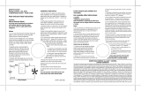
Speed settings for warm or cool weather depend on factors such as room size, ceiling height, number of fans and so on. The slide switch controls direction, forward or reverse.
Warm weather/down position - (Forward) Fan turns counterclockwise direction. A downward air flow creates a cooling effect as shown in illustration A. This allows you to set your air
conditioner on a higher temperature setting without affecting your comfort.
Cool weather/up position - (Reverse) Fan turns clockwise direction. An upward airflow moves warm air off the ceiling area as shown in illustration B. This allows you to set your heating unit
on a lower setting without affecting your
comfort. (Please however refer to point 10 in Safety Tips when operating in this position.)
NOTE: Turn off and wait for fan to stop before changing the setting of the forward/reverse slide switch.
Maintenance
1. Because of the fan’s natural movement, some connections may become loose. Check the support connections, brackets, and blade
attachments twice a year. Make sure they are secure.
2. Clean your fan periodically to help maintain its new appearance over the years. Do not use water when cleaning. This could damage
the motor, or the wood, or possibly cause electrical shock.
3. Use only a soft brush or lint-free cloth to avoid scratching the finish. The plating is sealed with a lacquer coating to minimize
discoloration or tarnishing.
4. There is no need to oil your fan. The motor has permanently lubricated bearings.

26
ETL-ES-Techno-WH14
TROUBLE
TROUBLESHOOTING GUIDE
If you have difficulty operating your new ceiling fan, it may be the result of incorrect assembly, installation, or wiring. In some cases,
these installation errors may be mistaken for defects. If you experience any faults, please check this Trouble Shooting Chart. If a problem
cannot be remedied, please consult with your authorized electrician and do not attempt any electrical repairs yourself.
1. If fan does not start: 1. check main and branch circuit fuses or circuit breakers.
2. check wire connections as performed in step #15 of installation.
CAUTION: Make sure main power is turned off.
3. Make sure forward/reverse switch is firmly in up or down position.
Fan will not operate when switch is in the middle.
4. If the fan still will not start, contact a qualified electrician.
Do not attempt to troubleshoot internal electrical connections yourself.
2. If fan sounds noisy: 1. check to make sure all screws in motor housing are snug (not over tightened).
2. check to make sure the screws which attach the fan blade holder to the motor are tight.
3. Some fan motors are sensitive to signals from Solid State variable speed controls.
DO NOT USe a Solid State variable speed control.
4. Allow “break-in” period of 24 hours. Most noises associated with a new fan will disappear after this period.
3. If fan wobbles: All blades are weighed and grouped by weight. Natural woods vary in density which could cause the fan to wobble even though all blades are weight-matched. The
following procedures should eliminate most of the wobble. check for wobble after each step.
1. check that all blades are screwed firmly into blade holders.
2. check that all blade holders are tightened securely to motor.
3. Make sure that canopy and mounting bracket are tightened securely to ceiling joist.
4. If blade wobble is still noticeable, interchanging two adjacent (side by side) blades can redistribute the weight and possibly result in smoother operation.
4. If light does not work: 1. check to see that the wire connections in the switch housing are connected.
2. check for faulty light bulbs.
3. If light kit will still not operate, contact a qualified electrician for assistance.
SUGGESTED REMEDY

Westinghouse Lighting, Philadelphia, PA 19154-1029, U.S.A.
www.westinghouselighting.com
, WESTINGHOUSE, and INNOVATION YOU CAN BE SURE OF
are trademarks of Westinghouse Electric Corporation.
Used under licensee by Westinghouse Lighting
All rights reserved.
Made in China
© 2014 WESTINGHOUSE LIGHTING
ETL-ES-Techno-WH14
/