1T-TG-620
HDMI Test Generator
Instruction Manual


Table of Contents
1.0
Introduction
2
2.0
Specifications
4
3.0
Checking Package Contents
5
4.0
Connecting the Hardware
5
5.0
Operating The Unit
6
6.0
Troubleshooting
15
7.0
Limited Warranty
15
8.0
Regulatory Compliance
16
9.0
Contact Information
17

2
1.0 INTRODUCTION
The 1T-TG-620 HDMI Test Generator provides a means to verify the correct
operation of HDMI equipment such as monitors and projectors. Any device with
an HDMI type input (plus PC or DVI-D displays with appropriate cable adaptors)
can be tested using several different types of test signals. A provision has been
made to embed either a 1Khz internally generated audio signal or an externally
generated audio signal in the digital bitstream so that operation of the audio
portion of the HDMI signal can be verified and, in addition, HDCP (High Definition
Content Protection) functionality can also be tested thereby insuring that all
video, audio and security components of the HDMI display device are functioning
properly.
Our professional video conversion products have been serving the industry for
over twenty years. tvONE offers a full line of high quality Seamless Switchers,
Video Scalers, Up/Down/Cross Converters, Analog-Digital Converters (SD/HD-
SDI, HDMI, DVI), Format Converters, Standards Converters, TBC/Frame
Synchronizers, Matrix Routing Switchers, Signal Distribution Amplifiers and Cat.5
Transmission Systems.
1.1 Liability Statement
Every effort has been made to ensure that this product is free of errors. tvONE
cannot be held liable for the use of this hardware or any direct or indirect
consequential damages arising from its use. It is the responsibility of the user of
the hardware to check that it is suitable for his/her requirements and that it is
installed correctly. All rights reserved. No parts of this manual may be
reproduced or transmitted by any form or means electronic or mechanical,
including photocopying, recording or by any information storage or retrieval
system without the written consent of the publisher.
tvONE reserves the right to revise any of its hardware and software following its
policy to modify and/or improve its products where necessary or desirable. This
statement does not affect the legal rights of the user in any way.
All third party trademarks and copyrights are recognised. The tvONE logo, AV
Toolbox logo, tvONE-task and CORIO are the registered Trademarks of tvONE.
All other trademarks are the property of their respective holders.
1.2 Features
HDMI v1.2, HDCP 1.1 and DVI 1.0 Compliant.
1.65Gbps Single Link HDMI Frequency Bandwidth.
EDID Support, VESA EDID v1.3 and EIA/CEA 861 Version 3
Supports PC & HD Video Inputs (Up to WUXGA60 and 1080p).
Supports Embedded Audio – Internally Generated and External.
Infrared Remote Control.

3
1.3 Getting the Best Results
There are many factors affecting the quality of results when dealing with HDMI
type signals. Some basic precautions will ensure the best possible performance
from your 1T-TG-620 HDMI Test Generator.
Output display device – The quality of the output signal will depend largely
upon the type and quality of the HDMI display device used. For instance,
some video projectors just look better than others.
Distance between the Test Generator and the display – This plays a major
role in the final result. Long distances are possible, but special measures
should be taken in order to avoid cable losses. These include using high
quality cables. Line amplifiers may also be necessary for the longest runs.
Input/Output connection cables – Low quality cables are susceptible to
interference. They degrade signal quality due to poor matching and can
cause elevated noise levels. Cables should be of the best quality.
Interference from nearby electrical devices – These can have an adverse
effect on signal quality. For example, an older computer monitor often emits
very high electromagnetic fields that can interfere with the performance of
video equipment in its proximity.

4
2.0 SPECIFICATIONS
Audio Input
Optical Audio (Ext. Audio)
1x S/PDIF via Toslink Connector
Video Output
HDMI
1x via Type A HDMI Connector (Note 1)
HDMI Transport
Frequency Bandwidth
1.65Gbps (Single Link)
Supported PC Resolution
Up to WUXGA/60
Supported HDTV Formats
480p, 576p, 720p, 1080i (Note 2) and 1080p
Audio (Embedded)
1Khz Sine wave Int. or Ext., 48Khz Sample Rate
Compliance
HDMI v1.2, HDCP V1.1, DVI V1.0
Special Feature
HDCP Functionality Check
Via Internal Algorithm
Video Test Patterns
36 Video Patterns
In 8 Groups
Control Methods
Local Control
Front Panel via Push Button Switches
Remote Control
1x Infrared Remote Control
Warranty
Limited Warranty
2 Years Parts and Labor
Mechanical
Size (H-W-D)
1.2”x4.9”x4.9” (30x125x125mm)
Weight (Net)
0.72lbs (334g)
Environmental
Operating Temperature
0 to +48C (+32 to +120F)
Operating Humidity
10% to 90%, Non-condensing
Storage Temperature
-10 to +70C (+32 to +120F)
Storage Humidity
10% to 90%, Non-condensing
Power Requirement
External Power Supply
5VDC@2A
Regulatory Approvals
HDMI Test Generator
FCC, CE, RoHS
Power Supply
UL, CUL, CE, PSE, GS, RoHS
Accessories Included
1x AC Power Adapter
US, UK or Euro Type
1x Instruction Manual
1x IR Remote Control
Product Number
1T-TG-620
HDMI Test Generator
Notes
(1) PC Video & DVI Video Operation is possible using optional adapters.
(2) The timing of the 1080i output signal is very critical; therefore it may not be
compatible with all displays.

5
3.0 CHECKING PACKAGE CONTENTS
Before attempting to use this unit, please check the packaging and make certain
the following items are contained in the shipping carton:
1x 1T-TG-620 HDMI Test Generator
1x 100~240VAC to 5VDC Power Adapter
1x Instruction Manual
1x Infrared Remote Control
Note: Please retain the original packing material should the need ever arise to
return the unit. If you find any items are missing, contact your reseller or tvONE
immediately. Have the Model Number, Serial Number and Invoice available for
reference when you call.
4.0 CONNECTING THE HARDWARE
Connect the HDMI Video Device’s HDMI input to the Output of the 1T-TG-620
Test Generator and connect an External Audio signal (if desired) to the
Generator’s S/PDIF Optical connector. The drawings below show the locations
of the front panel controls, input, output and power connector.
1T-TG-620 HDMI Test Generator
You can connect any HDMI compliant device’s input to the HDMI output. Make
certain that the HDMI cable is securely plugged into the destination device as
well as the HDMI Test Generator. Always use a high quality cable, as short a
length as possible, for best results.
4.1 Connecting Power to the 1T-TG-620
The unit is shipped with a Power Adapter to convert 100~240VAC@50-60Hz to
5VDC. Connect the DC Output Cable from the Power Adapter to the back of the
unit and then plug the Power Adapter into an AC Receptacle. The 1T-TG-620
HDMI Test Generator will begin to function as soon as it receives power. There is
no power switch.

6
5.0 OPERATING THE 1T-TG-620 HDMI TEST GENERATOR
The 1T-TG-620 HDMI Test Generator can be operated directly via the front panel
controls or via the included Infrared Remote Control. An On Screen Display
(OSD) provides a menu that allows you to select the test signal or function
desired using the front panel buttons. (Operation via the Remote Control will be
described later.)
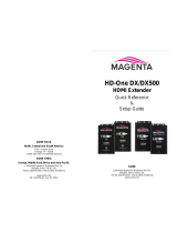
LED Display & Button Operation:
1 Power On/Off LED Indicator
2 HDCP On/Off LED Indicator
3 Remote Control Infrared Sensor
4 Resolution – Switches resolution sequentially in the following order:
VGA60→SVGA60→XGA60→SXGA60→UXGA60→WUXGA60→
576p50→480p60→720p50→720p60→1080i50→1080i60→1080p50
→1080p60
5 Menu - Used to display OSD Menu and make selections from the
Menu. (Note that the HDCP function turns off automatically when OSD
is present and turns back on when it is no longer visible.) *
6 Down Arrow moves OSD cursor towards the bottom of the display.
7 Up Arrow moves OSD cursor towards the top of the display.
8 Pressing the Menu and Down Arrow buttons at the same time will
return the 1T-TG-620 to the Factory Default setting.
* The Menu button is also the Enter Button. When you have reached the
pattern or adjustment you wish to utilize, pressing the Menu button allows
selection of the desired function or pattern and allows you to “Drill Down” into
the sub menus.
.

7
5.1 Menu Structure
Press [MENU] to show OSD Main Menu.
5.1.1 Pattern
On the Main Menu, press the arrow buttons as required to position the cursor
over the word “Pattern” and then press [Menu] to enter the pattern mode. There
are 8 different pattern groups available and you simply move the cursor and
press [Menu] to enter a particular pattern group. Press the up or down arrow
buttons to select previous/next pattern and select “Exit” to move back to the main
menu. Pressing Exit from the main menu will remove the OSD from the video
output.
The various patterns are shown below for reference purposes.
Color Bars
The color bar patterns provide a good overall check on color performance. This
includes the checks of burst keying, sub-carrier regeneration, RGB amplifier
balance, chrominance/luminance delay and a color saturation check.
Note that when the output resolution is 1080i, the horizontal Color Bar patterns
are not supported.
PATTERN
COLOR BAR
GRAY SCALE
PURITY
BLACKWHITE LINE
GRADUAL
GRID
HDCP PATTERN
OTHERS
EXIT
MAIN MENU
PATTERN
AUDIO SOURCE
HDCP SETUP
EDID ANALYSIS
RESOLUTION
SIGNAL TYPE
INFORMATION
EXIT

8
Gray Scale
The Gray scale pattern is used to locate non-linearity in a video amplifier. Non-
linearity results in compression of the white level and a loss of high frequency
detail.
Purity Check
The available purity colors are White, Blue, Red, Magenta, Green, Cyan, Yellow
and Black. The red and green patterns are most frequently used for checking
color purity.
In a correctly adjusted monitor, each electron beam will strike only one set of
color dots or stripes on the screen. If the red pattern is selected only this color
should be visible; the presence of any other color is an indication that color purity
needs adjustment.
The green pattern provides a purity check for three in-line tubes. In addition the
pattern serves as a reference to locate any geometrical distortions in these
picture tubes. In the in-line tubes, the guns are in a horizontal position and the
green gun is located in the center.
Blue, as well as the complementary colors, are often used to check the color
performance.
The other patterns (mainly RED) are used to ensure that there is no interference
between the sound and chroma carrier. In addition to the primary and
complementary colors 100% white can be selected as well as black pattern with
color burst. Purity patterns are also used for measuring unwanted amplitude and
phase modulation of the sub-carrier, AM and PM noise as it occurs with VCRs.

9
Black/White Lines
The vertical patterns provide a quick way to check the color monitor’s horizontal
bandwidth and phase behavior. They help verify video amplifier operation and
the display’s color temperature. The horizontal pattern serves as a quick way to
check of color monitor’s vertical bandwidth and phase response. Like the vertical
signals, they also are used to verify video amplifier bandwidth and display color
temperature.
Note: When the output resolution is 1080i, the patterns 4 , 5 and 6 are not
supported.
Gradual
These signals check adjustment of the decoders, especially the video de-
emphasis decoders. In a monitor, the chrominance signal should have the same
amplitude in the active video portion of the signal.

10
Grid
This pattern is mainly used for checking and aligning dynamic and corner
convergence of TVs or monitors. Note: When the output resolution is 1080i
50/60, the Grid patterns are not supported.
HDCP
This pattern is used to test DVI and HDMI monitors with HDCP capability. All DVI
and HDMI options, including analyzer options are supported if the HDCP option
is installed.
Others
The H pattern is mainly used for checking aligning dynamic convergence and the
Dot pattern is used for checking and adjusting the static convergence.

11
When using the Dot pattern, the screen should contain pure white dots. The
presence of colored dots points to problems with focusing and convergence.
The Cross center is used to check and adjust the geometric distortion. The Cross
center is ideal to center images on TV monitors and to facilitate alignment of
picture height/picture width. It is also used to check deflection linearity and
pincushion correction.
The Motion pattern is to check the correct digital video processing, especially
Analog to Digital conversion. When Motion pattern is On, the HDCP function will
be turned Off. When the user switches to other patterns, the HDCP function will
be turned back On.
5.1.2 Audio Source
Press the Arrow Buttons to move the cursor and then press [Menu] to enter the
audio source. After the audio source been selected press [Menu] to confirm the
selection.
As with all the OSD Menu items, select the Exit line and press the Menu button to
exit the Sub Menu and select Exit then press the Menu button from the Main
Menu display to exit the OSD entirely.
MAIN MENU
PATTERN
AUDIO SOURCE
HDCP SETUP
EDID ANALYSIS
RESOLUTION
SIGNAL TYPE
INFORMATION
EXIT
AUDIO SOURCE
INTERNAL
EXTERNAL
OFF
EXIT

12
5.1.3 HDCP SETUP
Press the arrow buttons to move the cursor and then press [Menu] to enter the
HDCP Setup. After the HDCP setup been selected press [Menu] to confirm the
selection. Press [Exit/Menu] to return to pervious page. Or press [Exit/Menu]
twice to return to the Main menu.
5.1.4 EDID ANALYSIS
MAIN MENU
PATTERN
AUDIO SOURCE
HDCP SETUP
EDID ANALYSIS
RESOLUTION
SIGNAL TYPE
INFORMATION
EXIT
HDCP SETUP
OFF
ON
EXIT
MAIN MENU
PATTERN
AUDIO SOURCE
HDCP SETUP
EDID ANALYSIS
RESOLUTION
SIGNAL TYPE
INFORMATION
EXIT
EDID ANALYSIS
BK0. Binary List
BK0. Vendor / Product Id
BK0. Basic Display Parameters
BK0. Color Characteristics
BK0. Established Timings
BK0. Standard Timings
BK0. Detail Timings
BK1. Binary List
BK1. DTV Monitor Support
BK1. Video Data Block
BK1. Audio Data Block
BK1. Other Data Block
BK1. Detail Timings
EXIT

13
Press the arrow buttons to move the cursor and then press [Menu] to enter the
EDID Analysis. After entering EDID analysis sub-menu, the user can move the
cursor and press [Menu] to check the EDID information. Press [Exit/Menu] to
return to pervious page. Or press [Exit/Menu] twice to return to the Main menu.
5.1.5 RESOLUTION
Press the arrow buttons to move the cursor and then press [Menu] to enter the
resolution setup. After the resolution setup been selected press [Menu] to confirm
the selection. Press [Exit/Menu] to return to pervious page or press [Exit/Menu]
twice to return to the Main menu.
5.1.6 SIGNAL TYPE
5.6 Signal type
Press [▲/
MAIN MENU
PATTERN
AUDIO SOURCE
HDCP SETUP
EDID ANALYSIS
RESOLUTION
SIGNAL TYPE
INFORMATION
EXIT
RESOLUTION
PC Mode: VGA60 / SVGA60 /
XGA60 / SXGA60 / UXGA60 /
WUXGA60
HD MODE: 576p50 /480p60 /
720p50 / 720p60 / 1080i50 / 1080i60
1080p50 / 1080p60
EXIT
MAIN MENU
PATTERN
AUDIO SOURCE
HDCP SETUP
EDID ANALYSIS
RESOLUTION
SIGNAL TYPE
INFORMATION
EXIT
SIGNAL TYPE
DVI
HDMI
AUTO DETECT
EXIT

14
Press the arrow buttons to move the cursor and then press [Menu] to enter the
signal type setup. After the signal type been selected press [Menu] to confirm the
selection. Press [Exit/Menu] to return to pervious page or press [Exit/Menu] twice
to return to the Main menu.
5.1.7 INFORMATION
Press the arrow buttons to move the cursor and then press [Menu] to show
system information. The system default status is shown in the example. Press
[Exit/Menu] to return to the Main menu. Note: After the user changes the system
status using the other menu options, the information status display will change.
5.2 Operation of the 1T-TG-620 via Remote Control
Operation of the 1T-TG-620 is possible via an
included Infrared Remote Control.
Note: When you unpack the HDMI Test
Generator, you may have to remove an
insulator from the battery compartment of the
remote in order for the remote to receive
power. The battery compartment slides out
from the bottom of the unit.
MAIN MENU
PATTERN
AUDIO SOURCE
HDCP SETUP
EDID ANALYSIS
RESOLUTION
SIGNAL TYPE
INFORMATION
EXIT
INFORMATION
RESOLUTION. 720P60
PATTERN. Color bar
AUDIO. Internal
HDCP. OFF
SIGNAL TYPE. AUTO DETECT
DVI (depends on EDID of display
device.)
EXIT

15
On the top row of the remote control, the Front Panel OSD Menu buttons on the
1T-TG-620 are duplicated. Operation is the same as described above.
The Remote Control also allows direct access to many of the functions of the
Test Generator by pressing the appropriate button on the remote.
For instance, you can press the Pattern button and then repeatedly press the
Group button and directly access the pattern group you want. Pressing the up
and down arrows will then allow you to move to the exact pattern you want and
pressing the menu button will then select the pattern.
By the same token, you can directly access a particular resolution, signal type
and so on. It is always possible to use the remote in the same manner as the
front panel buttons if you like.
6.0 TROUBLESHOOTING
In the event of problems, first make certain that the output cable is no more than
50 feet long (for signals to 1080i resolution) and is of the highest possible quality.
Next, make certain that the Test Generator is receiving power.
Generally, aside from cable problems and lack of power, the next most likely
area for problems is misuse or misunderstanding of the menu structure used in
the On Screen Display (OSD). Please take the time to read the instructions for
using the OSD Menu and if you become unsure of where you are in the menu
structure, press the Reset Button on the Remote so that you have a known
starting point.
If the 1080i output resolution does not work properly, please change to a different
resolution. As noted in the Specifications (Section 2), this resolution may not be
compatible with all displays.
After trying the above suggestions should the problem still persist, contact your
dealer for additional suggestions before contacting tvONE. Should the dealer’s
technical personnel be unable to assist you, contact tvONE via our support
website: http://tvONE.crmdesk.com. Create a technical support request on the
site and our support team will respond within a short period of time.
7.0 LIMITED WARRANTY
LIMITED WARRANTY – With the exceptions noted in the next paragraph, tvONE
warrants the original purchaser that the equipment it manufactures or sells will be
free from defects in materials and workmanship for a period of one year from the
date of purchase. Should this product, in tvONE’s opinion, prove defective within
this warranty period, tvONE, at its option, will repair or replace this product
without charge. Any defective parts replaced become the property of tvONE.
This warranty does not apply to those products which have been damaged due
to accident, unauthorized alterations, improper repair, modifications, inadequate

16
maintenance and care, or use in any manner for which the product was not
originally intended.
Items integrated into tvONE products that are made by other manufacturers,
notably computer hard drives and liquid crystal display panels, are limited to the
term of the warranty offered by the respective manufacturers. Such specific
warranties are available upon request to tvONE.
If repairs are necessary under this warranty policy, the original purchaser must
obtain a Return Authorization Number from tvONE and return the product to a
location designated by tvONE, freight prepaid. After repairs are complete, the
product will be returned, freight prepaid. LIMITATIONS - All products sold are "as
is" and the above Limited Warranty is in lieu of all other warranties for this
product, expressed or implied, and is strictly limited to two years from the date of
purchase. tvONE assumes no liability to distributors, resellers or end-users or
any third parties for any loss of use, revenue or profit.
tvONE makes no other representation of warranty as to fitness for the purpose or
merchantability or otherwise in respect of any of the products sold. The liability
of tvONE with respect to any defective products will be limited to the repair or
replacement of such products. In no event shall tvONE be responsible or liable
for any damage arising from the use of such defective products whether such
damages be direct, indirect, consequential or otherwise, and whether such
damages are incurred by the reseller, end-user or any third party.
8.0 REGULATORY COMPLIANCE
The 1T-TG-620 HDMI Test Generator has been tested for compliance with
appropriate FCC and CE rules and regulations. The Power Adaptor/Supplies
have been tested for compliance with appropriate UL, CUL, CE, PSE, GS Rules,
Regulations and/or Guidelines. These Products and Power Adapters are RoHS
Compliant.

17
9.0 CONTACT INFORMATION
Should you have questions or require assistance with this product in areas not
covered by this manual, please contact tvONE at the appropriate location.
tvONE USA
2791 Circleport Drive
Erlanger, KY 41018
USA
Tel 859-282-7303
Fax 859-282-8225
www.tvONE.com
tvONE Europe
Continental Approach
Westwood Industrial Estate
Margate, Kent CT9 4JG, UK
Tel +44 (0)1843 873311
Fax +44 (0)1843 873312
www.tvONE.eu
End of Manual
/