Page is loading ...

SEISCO (Water Heater) Installation Guide
1
SEISCO
®
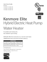
MOUNTING CLEARANCES
FRONT
VIEW
(Four-
Chamber
Unit)
12” *
SIDE VIEW
Minimum Mounting
Height: 10 inches
above floor ***
FLOOR
* Top Clearance : For removal of heating elements and to provide room for plumbing connections, a
minimum of 12 inches is required.
** Side clearance : Allow an overall minimum horizontal space for the heater of 24 inches for removal of
protective cover screws and access to electrical wires entering the heater from the side.
*** Mounting height : For safety, ease of installation and service, the suggested height above the floor is 42
to 48 inches, (minimum 10 inches). Do not install electrical disconnect or sub-panels below heater as this may
interfere with access to the clean out plates located under the heater.
**** Front Clearance : In the absence of a door or removal access panel in front of the heater, allow 32 to 36
inch clearance in front of the heater for protective cover removal and ease of service.
Mounting
Wall
6 ½ ”
15 ¾ ”
15 ¾ ”
Front
Clearance
(See Below)
****
Screw
Holes
14 ¾ ”
Screw
Holes
16 1/8 ”
24 ”
Horizontal Spacing**
FRONT VIEW
Two -Chamber Unit
Models
Rated
5KW to
14KW
Screw
Holes
14 ¾”
Screw
Holes
10 7/8”

SEISCO (Water Heater) Installation Guide
2
HUD Rules for Manufactured Housing
Where to Install
The Seisco water heater should be installed as specified in the Federal Manufactured Housing
Construction and Safety Standards (Standards). This was further clarified in a letter from HUD, dated Aug. 1,
2000.
In summary, the Seisco water heater can be installed in any room, including closets, alcoves, utility
rooms, and storage rooms, in which all walls and ceilings have a spread rating of 25 or less. Walls and ceilings
consisting of unpainted or painted 5/16 inch or greater gypsum board or 5/16 inch or greater tape/textured
gypsum board meet these flame spread ratings. When installed in such a room, the Seisco can be mounted at
any convenient location and without any additional enclosure.
If any of the walls or ceilings in a room have vinyl covered gypsum board, 5/16 inch or greater, the
room may not meet the flame spread index of 25 or less, for the purpose of installing the Seisco water heater. If
one or more of the walls is paneling, the 25 or less flame-spread rating is not met. In these situations, the Seisco
water heater can be installed if a surrounding enclosure is constructed of 5/16 inch or greater gypsum. Vinyl
covered gypsum board that is labeled with a flame-spread rating of 25 or less is acceptable to use in the water
heater compartment without any additional enclosure.
Prevention of Storage
When the Seisco water heater is installed in a closet, storage room or similar room, the area surrounding
the appliance should be framed-in or guarded with noncombustible material such that the distance from the
appliance to the framing or guarding is not greater than 3 inches. (When clearance required by the listing is
greater than 3 inches, the guarding or framing shall not be closer to the appliance than the distance required by
the listing.)
Clearance spaces surrounding the Seisco water heater are not required to be framed or guarded when:
1. the space is specifically design for a clothes washer or dryer;
2. dimensions surrounding the appliance do not exceed 3 inches; or
3. the home manufacturer affixes either to the side of the storage area or closet containing the
appliance, or to the appliance itself, in a clearly visible location, a 3”X5” adhesive backed plastic
laminated label or the equivalent which reads as follows:
“Warning”
This compartment is not to be used as a storage area. Storage of combustible materials or containers on or
near any appliance in this compartment may create a fire hazard. Do not store any materials or containers in
this compartment.
All Seisco water heaters shipped to Manufactured Home Builders will have a warning label as shown
above on the exterior of the heater.
Temperature and Pressure (T&P) Valves
As of August 1, 2000, there is no longer a requirement to install a T&P Valve with the Seisco water
heater. The HUD letter recognizes and accepts the Underwriters Laboratories, Inc. (UL) Standard 499 endorsing
the National Electrical Code (NEC) as an appropriate standard to the installation of valves for temperature and
pressure relief as mandated by Standard 3280.609(c). Since the Seisco water heater meets the requirements of
UL 499 and NEC as a tankless water heater, there is no requirement for a T&P Valve when the Seisco water
heater is installed in a Manufactured Home.
Also see - Water Heater Controls, National Electrical Code, NEC, 422-47
FPN: See Relief Valves and Automatic Gas Shutoff Devices for Hot Water Supply Systems, ANSI Z21.22-986.

SEISCO (Water Heater) Installation Guide
3
PLUMBING INSTALLATION GUIDE
NOTE: This water heater must be installed to meet the current National Electric Code,
and any applicable Local Plumbing, Electrical, Heating and Air Conditioning Codes.
GENERAL
Unpack the water heater from the shipping carton carefully. DO NOT CUT THE SHIPPING
CARTON WITH A SHARP INSTRUMENT. Stand the unit upright and remove the plastic wrap.
Locate the four (4) mounting holes in the metal back plate. Position the unit against the wall with the
two inlet and outlet fitting tubes pointed up toward the ceiling. Refer to Mounting Clearances in this
section of the manual. Make sure the unit is level and attach to the wall with ¼ inch or larger lag bolts
that are at least 1 ½ inches long. If attaching to sheet-rock or paneling, anchors or molly bolts should
be used to prevent the screws from pulling through the wall. If the water heater is to be installed on a
cinder block or concrete wall, attach a ½ or ¾ inch section of plywood (20” x 20 “ square) to the wall
first. Then use wood screws to attach the water heater to the plywood.
PROPERTY DAMAGE PROTECTION
IF THE WATER HEATER IS INSTALLED IN ANY AREA WHERE LEAKAGE OF
THE TANK OR CONNECTIONS WOULD RESULT IN DAMAGE TO THE AREA
ADJACENT TO THE WATER HEATER, OR WHERE SUCH A LOCATION IS
UNAVOIDABLE, A SUITABLE DRAIN PAN OR FLOOR DRAIN WAS NOT INSTALLED
UNDER THE WATER HEATER.
WHEN A DRAIN PAN MUST BE USED, THE PAN MUST MEET ALL APPLICABLE
PLUMBING CODES AND BE AT LEAST 1-1/2” DEEP, EXTENDING NOT LESS THAN 1”
ABOUT THE UNIT’S BASE PLATES, MUST PROTECT AN AREA AT LEAST 1-1/2”
GREATER THAN THE LOWER EXTERNAL DIMENSIONS OF THE WATER HEATER,
INCLUDE A SPLASH COVER FOR THE AREA OF ATTACHMENT TO THE WALL, AND
MUST BE PIPED BY 1” PIPE TO AN ADEQUATE DRAIN.
Exception: Drain Pan is not required in first floor installations in manufactured housing when the
home is manufactured under the HUD Standard.
PLUMBING CONNECTIONS
ATTACHING WATER SUPPLY /
WARNING #1: Always use two wrenches when making any attachments of the water supply. Hold
the water heater’s inlet and outlet fittings secure while attaching the cold water and hot water lines.
Never attempt to attach water lines to the heater’s fittings without using a second wrench to hold the
fittings secure. The heater’s inlet and outlet fittings are designed to turn freely.
WARNING #2: Never solder water supply lines to the water heater’s fittings. Heat from the soldering
may damage the heat exchanger.

SEISCO (Water Heater) Installation Guide
4
WARNING #3: Do not use Plumber’s Putty or PVC/CPVC primer and glue on the threads of the
water heater’s inlet and outlet fittings. Some of the putty compounds on the market are very aggressive
and could potentially dissolve the threads on the heater’s fittings. PVC/CPVC primer and glue will also
dissolve the threads on the heater’s fittings. Teflon Tape is the only sealer that should be used on the
threads of the inlet and outlet fittings.
TEMPERATURE & PRESSURE VALVE/
A temperature and pressure relief valve (T&P Valve) may be required by local code.
When a T&P valve is installed (which is not provided by the manufacturer), it should be checked after
the water supply to the heater is turned on. With the water supply on, there should be no water flowing
from the valve. Operate the valve manually two or three times to purge the trapped air from the top of
the heater’s chamber. CLOSE VALVE. Water should stop flowing completely prior to connecting the
drain piping to the valve.
SINCE THE SEISCO WATER HEATER DOES NOT UTILIZE A STORAGE TANK, THE
USE OF A T&P RELIEF VALVE IS NOT REQUIRED BY MANY NATIONAL STANDARDS,
INCLUDING UL STANDARD 499. Seisco heaters are designed with control logic as well as
elctro-mechanical high limit thermostat switches for over-temperature protection. With these
built-in safety features, the use of a T&P Relief Valve is not required.
DRAIN PAN/
If the Seisco heater is installed in an area where water damage can occur to the area adjacent to
the heater, a drain pan must be installed. The pan must be at least 1 ½ inches deep and large enough to
protect the area below the heater (the pan should be at least 1 ½ inches larger than the lower external
dimensions of the heater) and must be piped by 1 inch pipe to a suitable drain. A splash cover must be
included to protect the area of attachment to the wall.
NOTE: THIS WATER HEATER MUST BE INSTALLED TO MEET THE CURRENT
NATIONAL ELECTRICAL CODE, AND ANY APPLICABLE LOCAL PLUMBING,
ELECTRICAL, OR HEATING AND AIR CONDITIONING CODES.
SEISCO
SEISCO
HOT
HOT
COLD
COLD
Above diagram shows approved
plumbing connections without
T&P Valve (T&P NOT REQUIRED
BY MANUFACTURERER).
Above diagram shows plumbing
connections with a T&P Valve if
required by local codes.
T&P
Valve

SEISCO (Water Heater) Installation Guide
5
ELECTRICAL INSTALLATION GUIDE
CONNECTION TO POWER SUPPLY
NOTE: In the U.S., this unit must be installed to meet the current National Electric Code, and
any applicable local plumbing, electrical, heating and air conditioning codes. In Canada,
conductor and breaker sizes cannot be less than 125% of the circuit rating of the heater.
WARNING: Installation and service must be by qualified personnel only!
Install wiring (see wiring diagram) from the unit to the Main Power Circuit Breaker Panel. Connect the wiring
to the unit as shown on the wiring diagram attached to the inside of the unit's cover.
WARNING
MODELS RATED 14KW* THRU 28KW*
REQUIRE MULTIPLE POWER SOURCES.
WHEN WIRED DIRECTLY TO THE BREAKER
BOX, THEY REQUIRE MORE THAN ONE
DOUBLE POLE CIRCUIT BREAKER.
RISK OF ELECTRICAL SHOCK. HEATING
ELEMENT IS NOT GROUNDED. SOME UNITS
HAVE MULTIPLE POWER SUPPLIES.
DISCONNECT ALL POWER SUPPLIES BEFORE
SERVICING.
IF USING STRANDED WIRE, MAKE SURE
THAT ALL STRANDS ARE IN SECURE
PLACEMENT IN THE TERMINAL BLOCK. A
LOOSE STRAND IN CONTACT WITH THE
CIRCUIT BOARD CAN IMPAIR
PERFORMANCE OR DAMAGE THE BOARD.
HEATER SUPPLY SIDE CONNECTION
FOR MODELS RATED 5KW THRU l1KW, ONE
PAIR OF WIRES SHOULD BE ATTACHED
WITHIN THE UNIT AT POWER CIRCUIT 1
(CKT 1)-ONE WIRE TO L1 AND ONE WIRE TO
L2. FOR MODELS 14KW* THRU 22KW, A
SECOND PAIR OF WIRES MUST ALSO BE
ATTACHED AT POWER CIRCUIT 2 (CKT2)-
ONE TO Ll AND ONE TO L2. FOR MODEL
RATED 28KW*, A THIRD AND FOURTH PAIR
OF WIRES ARE REQUIRED FOR POWER
CIRCUITS 3 AND 4 (CKT 3 & CKT 4).
*The U.S. NEC branch circuit rule has changed
which allows the option to wire the 14KW unit with
one 60 AMP circuit and the 28KW unit with two 60
AMP circuits. In Canada, these circuits must be
rated for 75 AMPS. Jumpers must be installed on
the control board before using these wiring options.
MAIN POWER CIRCUIT BREAKER
WHERE REQUIRED BY CODE, USE A
DISCONNECT SWITCH ADJACENT TO THE
WATER HEATER. WHEN MAKING THIS
TYPE OF INSTALLATION, BE SURE THE
MAIN FEEDER WIRES USED ARE
PROPERLY SIZED.

SEISCO (Water Heater) Installation Guide
6
Install the proper size circuit breaker (see Product Specifications). Be sure that the unit-to-power supply circuits
are properly connected. For models rated 5KW thru 1lKW, the pair of feeders attached to power circuit 1 (CKT
1) should be attached to one 2-pole breaker, and for models rated 14KW* thru 22KW, the second pair attached
to power circuit 2 (CKT 2) should be attached to a second 2-pole breaker such that the total load will be
balanced. For model rated 28KW*, two additional breakers are required for power circuits 3 and 4 (CKT 3 & 4).
*In the U.S., the NEC branch circuit rule has changed which allows the option to wire the 14KW unit with
one 60 AMP circuit and the 28KW unit with two 60 AMP circuits. In Canada, these circuits must be rated
for 75 AMPS. Jumpers must be installed on the control board before using these wiring options.
PRE-POWER CHECK
1. After all electrical connections have been made, every effort should be made to verify a safe installation.
Again check to be sure all connections in the unit disconnect and/or circuit breaker panel are secure. Check to be
sure that an adequate ground has been properly connected. Check to be sure that adequate size breakers have
been installed properly. Remember that breakers that are too large are more dangerous than breakers that are too
small.
2. RUN WATER THROUGH THE UNIT UNTIL AIR IS PURGED.
POWER CHECK
Check only after the Pre-Power Check has been completed and the unit filled with water. Turn on the Main
Power Circuit Breakers. Verify that the water heater’s GREEN POWER-ON “FLASHING” indicator light is
illuminated.
USE EXTREME CAUTION WHEN CHECKING VOLTAGE TO THE UNIT.
Check the voltage available to each active power circuit. SEISCO models rated 5KW to 28KW are designed to
operate from a 208V to 240V power supply. Connect a voltmeter at power circuit 1 (CKT 1) between L1 and L2.
(For models with multiple power circuits utilized, continue to check voltage at each additional power circuit.)
OPERATIONAL CHECKS
Turn water on MEDIUM-LOW utilizing any sink allowing water to run for a couple of minutes to ensure that
all air is purged from the unit. You will hear a "click" as the relays on the circuit board engage. It is normal to
hear a “hissing” or "crackling" noise from the heat exchanger after the unit is started. With the unit's cover
removed, verify with an ammeter that there is ELECTRICAL CURRENT through each heating element circuit.
DISREGARD THE WATER TEMPERATURE WHILE DOING THIS TEST.
TURN OFF FAUCETS after completing Operational Check.
Thermostat settings are factory preset to approximately 120 degrees F for units employing a circuit board
potentiometer (thermostat).
THIS INSTALLATION MUST BE DONE BY QUALIFIED AND LICENSED CONTRACTORS. Refer
to your local electrical and plumbing codes for additional information.

SEISCO (Water Heater) Installation Guide
7
Start-Up Functional Checks
After the initial start-up, following the Pre-Power and Operational Checks described in the Electrical
Installation section of this manual, it may be necessary to make adjustments to the system to insure that
the water heater is functional and providing hot water.
Beeps & Flashing Lights – What do they Mean?/
It is normal at start-up or any time the water heater is powered-on for the control board to beep and the
LED to flash red and then green. Normal status of the heater is for the control to flash all green
repeatedly. The initial 2 to 4 red flashes and beeps after power-on are normal, but should not continue.
SEISCO Provides On-Board Self Diagnostics/
However, in the event that the LED light continues to flash a red sequence after power-on, then there may
be a need for further investigation. The heater’s control provides self diagnostics by emitting a red
flashing code. The code definitions and possible solutions can be found in the Trouble Shooting section
of the Seisco Service Manual.
Some of the most common problems discovered during installation and initial start-up are as follows:
• Circuit breakers are not turned-on (especially, heaters with multiple circuits)
• Incoming power wires to the water heater are out-of-phase (heaters with multiple circuits)
• Water supply valve not turned-on, no water in the heater chamber
• Water supply lines are reversed; hot and cold reversed
• Water supply connection(s) are leaking
• T&P Relief Valve (where required by local code) is leaking or stuck open
The Seisco Heater Alerts the User of Water Leaks!/
Diagnostic codes are designed to tell the installer or user if there is a problem and what the problem might
be. Also, the water heater has a built in alarm that will sound if there is water leaking onto the water
heater, possibly from a leaky water line connection or from a leaky T&P Relief Valve. Check equipment
connected nearby the water heater for the possibility of leaks and spraying onto the water heater. It is
important to turn off all of the circuit breakers and water supply to the water heater whenever a leak
is detected to prevent possible damage to the control board. After the leak is discovered and repaired, it is
important to dry any moisture or water accumulation on the water heater. This can be done with a
standard household hair dryer or dry towels. Any attempts to dry the water heater should be done with all
the power off to the water heater.

SEISCO (Water Heater) Installation Guide
8
System Match – Faucets and Heater/
When a Seisco water heater is selected for the home or building, the faucets should also be selected to
match the flow rating and temperature rise specifications of the heater. The Seisco water heater
specifications can be found in the Product Description and Specifications section of the Product Guide.
Sometimes, this is overlooked and the user discovers that the faucets in the home are a higher flow rate
than the design of the Seisco model(s) selected.
Solutions for High Flow Applications/
Another oversight may be the lifestyle of the user. For instance, if the user wants to take two showers at
the same time or run the washing machine and the bathtub at the same time, then the flow rate demands of
the water heater are increased, sometimes beyond the capability of the Seisco heater. Multiple Seisco
heaters are used for higher flow applications, such as for multiple task lifestyles, whirl pool and Jacuzzi
tubs and body spa showers as well. Refer to Product Applications and Diagrams section of the Product
Guide for recommended multiple Seisco heater arrangements. Note, it is important to evaluate the
electrical capacity of the home or building when selecting multiple Seisco heaters for a high flow
application. Refer to the Electrical Service Requirements and Sample Load Calculations section in the
Product Guide.
Typical Flow-Use Rates in Gallons per Minute (gpm)
Fixture
Type
Lavatory
Bathtub
Shower
Kitchen
Sink
Pantry
Sink
Laundry
Sink
Dish-
Washer
Flow
Rates
0.8 – 1.5
2.0 – 4.0
1.5 – 3.0
1.0 – 1.5
1.5 – 2.5
2.5 – 3.0
2.0 – 3.0
Temperature Adjustment/
After the water heater has been installed and the operational checks are completed, the output of the hot
water can be measured and adjusted if necessary. The temperature-adjusting knob can be found on the left
side of the control board. The factory setting is usually between 118 and 122 degrees F. The knob will
usually be in the 2 to 3 o’clock position. Turning the knob to the left decreases the temperature and
turning it to the right increases the temperature.
Note: it is important to understand the effects of increasing the temperature above the factory setting as
follows:
1. A higher temperature setting could cause the water heater to use more power, thus energy savings are
reduced.
2. A higher temperature setting could increase the potential for scaling and sediment build-up.
3. The water heater may not achieve a higher temperature setting, if the flow rate is greater than its
designed temperature rise capacity. Check to insure that the proper size model has been chosen for the
application.
/