Page is loading ...

OWNER’S MANUAL
FOR MAXIMUM EFFECTIVENESS AND
SAFETY, PLEASE READ THIS OWNER’S
MANUAL BEFORE USING YOUR
EDGE 1400 Elliptical Trainer.
1400
Elliptical Trainer

Important Safety Instructions ...........................................................2
Equipment Warning Labels ..............................................................3
Specifications & Parts .......................................................................3
Introduction .......................................................................................4
Assembly Instructions...................................................................5-12
Edge 1400 Parts List.........................................................................13
Edge 1400 Exploded View .............................................................14
Getting Started ...............................................................................15
Using Your Elliptical Trainer...................................................16
Using The Handlebars .....................................................16-17
Changing Foot Positions ......................................................17
Adjusting the Stride Length.................................................17
Operating the Monitor ..............................................................18-20
Care & Storage of Your Elliptical Trainer.......................................21
Exercise Guidelines .........................................................................22
Knowing the Basics....................................................................22
A Complete Exercise Program............................................22-23
Aerobic Exercise: How Much? How Often? ...........................23
When to Exercise .......................................................................23
Measuring Your Heart Rate .................................................23-24
Clothing ......................................................................................24
Tips to Keep You Going.............................................................24
Heart Rate Target Zone Chart..................................................25
Warm Up & Cool Down Stretches ...........................................26-27
Progress Charts................................................................................28
TABLE OF CONTENTS
©2006 and ©2007 Fitness Quest Inc. All rights reserved. Made in Taiwan.
Edge
® and Fitness Quest® are registered trademarks of Fitness Quest Inc.
U. S. Utility Patent #6,629,909. Other U.S. and foreign patents pending.
2/5/07

2
IMPORTANT SAFETY INSTRUCTIONS
1) Before starting this or any other exercise
program, consult your physician, who can assist
you in determining the target heart rate zone
appropriate for your age and physical condition.
Certain exercise programs or types of equip-
ment may not be appropriate for all people. This
is especially important for people over the age
of 35, pregnant women, or those with pre-existing
health problems or balance impairments.
2) Monitor your heart rate while you exercise
and keep your estimated pulse rate within your
target heart rate zone. Follow the instructions
on pages 23 – 24 in this manual regarding heart
rate monitoring and how to determine your
appropriate target heart rate zone. When used
properly, the heart rate pulse sensors and display
monitor provide a reasonably accurate estimate
of your actual heart rate. This estimate is not
exact and persons with medical conditions
and/or a specific need for accurate heart rate
monitoring should not rely on the estimations
provided.
3) Warm up before any exercise program by doing
5 - 10 minutes of aerobic activity, followed by
stretching.
4) Wear comfortable clothes that allow freedom of
movement and that are not tight or restricting.
5) Wear comfortable shoes made of good support
with non-slip soles.
6) Breathe naturally, never holding your breath
during an exercise.
7) Avoid over training. You should be able to carry
on a conversation while exercising.
8) After an exercise session, cool down with slow
walking and stretching.
9) Start exercise slowly and gradually increase the
amount of resistance.
10) If the user experiences dizziness, nausea, chest
pain, or any other abnormal symptoms, stop
exercise at once and consult a physician
immediately.
11) THIS EQUIPMENT IS NOT FOR USE BY CHILDREN.
To prevent injuries, keep this and all fitness
equipment out of the reach of children.
Follow these simple rules:
– Keep children out of rooms where you
have your exercise equipment.
– Store exercise equipment in a room that
can be locked.
– Know exactly where your children are
when you work out.
– If you have small children at home, don’t
wear headphones while you work out.
– Talk to your kids about the dangers of
exercise equipment.
12) Handicapped or disabled people must have
medical approval before using this equipment
and should be under close supervision when
using any exercise equipment.
13) If you are taking medication which may
affect your heart rate, a physician's advice
is absolutely essential.
14) Use this equipment only for its intended use as
described in this manual. Do not use attach-
ments not recommended by the manufacturer.
15) Only one person at a time should use this
equipment.
16) Do not put hands, feet, or any foreign objects on
or near this equipment when in use by others.
17) Always use this equipment on a solid, level
surface.
18) Never operate the equipment if the equipment
is not functioning properly.
19) Use caution not to pinch fingers or hands in
moving parts when using the equipment.
20)
Risk of electrical shock. This equipment is to be
used only indoors and in a dry location.
Read all instructions before using this equipment
KEEP THESE INSTRUCTIONS
WARNING
YOU AND OTHERS CAN BE SERIOUSLY INJURED OR KILLED
IF WARNINGS ON THE EQUIPMENT AND IN THIS OWNER’S
MANUAL ARE NOT FOLLOWED.

3
Important: See below for placement of the following warning labels on your equipment.
Edge 1400
Specifications:
Approximate:
Length: 50”
Width: 28”
Height: 63”
EEL1406R
Right Foot
Platform
•
EEL1406L
Left Foot
Platform
•
Product Weight:
Approx. 186 lbs.
Maximum User Weight:
300 lbs.
WARNING
LABEL 2
WARNING
FAILURE TO READ AND FOLLOW THE SAFETY INSTRUCTIONS STATED IN THE
OWNER’S MANUAL MAY RESULT IN POSSIBLE SERIOUS INJURY OR DEATH.
KEEP CHILDREN AWAY. MAXIMUM USER WEIGHT 300 LBS.
REPLACE THIS LABEL IF DAMAGED, ILLEGIBLE OR REMOVED. CLASS HC.
WARNING LABEL 1
WARNING LABEL 3
WARNING
LABEL 1
WARNING
LABEL 3
EQUIPMENT WARNING LABELS
SPECIFICATIONS
& PARTS
RISK OF ELECTRICAL SHOCK. THIS UNIT
IS TO BE USED ONLY
INDOORS
AND IN A DRY LOCATION.
DO NOT PLUG THE AC ADAPTER INTO
WALL UNTIL ELECTRONICS MONITOR IS
COMPLETELY ASSEMBLED.
WARNING LABEL 2
WARNING
•
NB9001-1
Leveler
•
NB9010
Water Bottle
Holder
•
NB9015-2A
End Cap
•
NB9009
Water Bottle
•
NB9002-2
Right Frame
Cover
•
NB9002-1
Left Frame
Cover
E
EL1405L
Left
Handlebar
A
ssembly
•
E
EL1405R
Right
H
andlebar
Assembly
•
E
EL1405-1
Hand Pulse
G
rips
•
•
NB8002-4
Stride
Adjustment
Knob
•
NB9008
Swing Arm
Cover
•
AC Adapter
Receptacle
•
EEL1401
Base Frame
Assembly
EEL1412
M
onitor
•
E
EL1407
Stationary
Handlebar
•
NB9013
AC Adapter
CRUSH HAZARD.
KEEP HANDS
CLEAR OF MOVING
PARTS DURING
OPERATION.
WARNING

4
COMMENTS OR QUESTIONS
Dear Customer,
Congratulations on your purchase of your
Elliptical Trainer.
We’re sure that you will be completely satisfied
with the product and we invite your comments
so that we can hear about your success.
Please write or call our Customer Service Specialists
at the address or phone number listed below, or
contact us by email or on our web site, with any
comments or questions you may have.
Edge 1400 Elliptical Trainer
Customer Service Department
1400 Raff Road SW, Canton OH 44750-0001
1-800-321-9236, Monday through Friday
8:30am to 8:00pm, Eastern Standard Time
email: customersupport@fitnessquest.com
www.fitnessquest.com
All details depicted in this Owner’s Manual, and of the
product itself, are subject to change without notice.
ORDERING REPLACEMENT PARTS
When ordering parts, please contact our
Parts Department, toll free at 1-800-497-5831,
Monday through Friday, 8:30am to 8:00pm, EST.
IMPORTANT: You must have your serial number and
this manual ready when calling for parts.
Serial #: _______________________________
Please also provide the following information:
1) Name, Mailing Address and Telephone Number
2) Date of Purchase
3) Where Product was Purchased
(Name of Retail Store, City)
4) Model Number (EEL1400)
5) Part Order Number and Description
W
ith this product in your home, you have everything you need to start
your own workout program to tone and firm the major muscle groups of
your lower body. This is vital for all of us, regardless of age, sex, or fitness
level, and regardless of whether your primary goal is toning, health
maintenance, or more energy for daily activities.
Proper exercise, including a low fat diet, strength training and aerobic
exercise, tones and conditions the muscles we use every day to stand,
walk, lift and turn. It can actually transform our body composition by
reducing body fat and increasing the proportion of lean muscle in
our bodies. Using the Elliptical Trainer will help in reducing body fat
and increasing cardiovascular endurance.
Be sure to read through this Owner’s Manual carefully.
It is the authoritative source of information about your
Elliptical Trainer.
Retain this manual for future reference.
CONGRATULATIONS ON PURCHASING YOUR
EDGE 1400 ELLIPTICAL TRAINER
INTRODUCTION

Occasionally our products contain components that are
pre-lubricated at the factory. We recommend that you
protect flooring, or anything else the parts may contact,
w
ith newspaper or cloth.
ASSEMBLY INSTRUCTIONS
NOTE: All location references, such as front,
rear, left or right, made in these instructions
are from the user being on the equipment
and facing forward.
Tools Required (included):
Allen Wrench 5mm & 6mm
Phillips Screwdriver
Socket Wrench 17mm
Open End Wrench 17mm
E
EL1406R
Right Foot
Platform
E
EL1406L
Left Foot
P
latform
EEL1402-6R
Right
Swing Arm
Assembly
N
B8015FB
Fastener Bag
(
Steps 1-9)
R
ight
Frame
T
ube
L
eft
Frame
T
ube
EEL1403L
Left Rocker
Arm
EEL1403R
Right Rocker
Arm
EEL1402-6L
Left
Swing Arm
Assembly
NB9010
Water Bottle Holder
NB9008
Swing Arm
Covers
NB9013
AC
Adapter
EEL1405L
Left Handlebar
Assembly
EEL1405R
Right
Handlebar
Assembly
EEL1402
U
pright Frame Assembly
NB9009
Water
Bottle
EEL1407
Stationary
Handlebar
Assembly
EEL1401
Base Frame
Assembly
EEL1404R
Right
Foot
Tube
EEL1404L
Left
Foot
Tube
EEL1412
Monitor
5
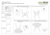
Lay all the parts out
on the floor as shown
to familiarize yourself
with them.
– TOP LAYER –
– MIDDLE LAYER –
– BOTTOM LAYER –
NB9015-11
Tool Bag

6
STEP 1 – Upright Frame Assembly
You will need two people to assemble the Upright
Frame Assembly (shown in 1b) to the Base Frame
Assembly.
Remove Cable Tie from Wire in Base Frame Tube.
a) With the Monitor Bracket to the rear of the
unit and Stride Adjustment Knobs to the front
(shown in 1b), carefully lift the Upright Frame
Assembly above the front of the Base Frame.
Keeps hands clear of moving Swing Arms.
You will need a second person to attach
the Wire coming from the Front Base Frame
Tube to the Wire inside the Left Frame Tube.
Tuck excess Wire into Left Frame Tube.
b) Slide the Upright Frame Assembly onto the
Front of the Base Frame. Insert 4 Bolts into
the side of Right and Left Frame Tubes. Then
insert a small Bolt into the front and 2 small
Bolts into the rear of each Frame Tubes.
Tighten all Bolts with the 5mm Allen
Wrench provided.
ASSEMBLY INSTRUCTIONS
left frame tube
front base
frame tube
(left side)
FRONT
monitor
bracket
upright
frame
assembly
base frame tube
(right side)
REAR
FRONT
stride
adjustment
knob
left frame
tube
attach
wires
1a
1b
8 - M8 x 55mm
allen bolts
w/lock washer
6 - M8 x 16mm
allen bolts
w/lock washer
CAUTION
UPRIGHT FRAME ASSEMBLY IS HEAVY. YOU WILL
NEED TWO PEOPLE TO ASSEMBLE THIS PART.

7
STEP 2 – Top Rocker Arm
Attachment
Slide the Left Rocker Arm onto the
Left Swing Arm. Attach with Hex
B
olt, Washer and Lock Washer.
Tighten with Socket Wrench
provided. Insert Cap. Repeat
on right side.
STEP 3 – Bottom Rocker
Arm Attachment
Attach the bottom of Left Rocker
Arm to the small Crank Bearing
w/4 Allen Bolts. Start all 4 Allen
Bolts before tightening. Follow the
sequence A through D as shown.
Note: The hole for Bolt D is not
shown, but is located under the
Rocker Arm.
For ease of assembly, we suggest
you place the Bolt onto the end
of the Wrench. This may help
prevent the Bolt from falling
into the Rocker Arm.
Tighten with the 6mm Allen
Wrench provided.
Repeat on right side.
left rocker
arm
washer
left swing
arm
right swing arm
cap
3
cap
right rocker
arm
*Rocker Arm placement
between
Frame Tube
and Swing Arm (shown
on outside for easy
reference).
frame tube
2
2 - M10 x 20mm hex bolts
2 - M10 washers
2 - M10 lock washers
2 - caps
small crank
bearing
(rear of unit shown)
crank
small crank
bearing
left rocker arm
right rocker arm
bolt
lock washer
*Important Note:
Rocker Arms should
be placed on the
inside of the unit -
between the Frame
Tube and Swing
Arm. The illustration
shows them on the
outside for your
easy reference.
8 - M8 x 12mm allen bolts
A
A
D
D
B
B
C
C

8
STEP 4 – Foot Platform Assembly
A
ttach the Left Foot Platform to the Left Foot Tube as shown
with 6 Phillips Bolts. Tighten with Phillips Screwdriver provided.
Repeat on Right Foot Tube.
STEP 5 – Foot Tube/Swing Arm
Assembly
Place the front of the Right Foot Tube
into the Right Swing Arm Bracket at the
bottom of the Right Swing Arm. Attach
with Hex Bolt and Hex Nut. Tighten with
the Socket Wrench and Open End
Wrench tools provided.
Repeat on the Left Swing Arm.
4
5
left foot platform
REAR
FRONT
FRONT
left foot tube
right foot tube
right swing arm bracket
right swing arm
12 - M5 x 16mm phillips bolts,
6 bolts used on each
Foot Platform Assembly
2 - M10 x 82mm hex bolts
2 - M10 hex nuts

9
STEP 7 – Handlebar Assembly
Slide Left and Right Handlebar
Assembly over the top of the Swing
Arm Assembly and insert 3 Allen
Bolts per side. Hand tighten first
to begin all Allen Bolts. Then,
tighten Allen Bolts with the 5mm
Allen Wrench provided.
STEP 6 – Swing Arm Covers
Attach the Swing Arm Covers
o
n the front of the Swing Arms
with Phillips Bolts. Tighten with
the Phillips Screwdriver provided.
6
swing arm
covers
2 - M6 x 12mm
phillips bolts
NOTE: If you find it difficult to get
the Bolt started, first thread the
Bolt into the hole on the Swing
Arm without the Cover. Then,
remove the Bolt and repeat
Step 6 above.
7
right
handlebar
assembly
REAR
FRONT
right swing arm
assembly
left swing arm
assembly
pulse
wire
pulse wire
upright
frame
assembly
left
handlebar
assembly
6 - M8 x 20mm
allen bolts

10
STEP 8 – Install Monitor, Water
Bottle Holder and
Stationary Handlebar
Two people are required to do this step.
a) Remove 4 Phillips Bolts from the back of
the Monitor. Remove Cable Tie from top of
Stationary Handlebar Assembly. Connect
Monitor Pulse Wires to the Pulse Extension
Wires. Connect Monitor Extension Wire to
the Monitor. Attach the Monitor to the
Bracket on the Stationary Handlebar
Assembly with the Phillips Bolts you removed
at the beginning of this step and tighten
with Phillips Screwdriver provided.
b) Remove the Cable Tie from the bottom of
the Stationary Handlebar Assembly. Slide
the Water Bottle Holder over the bottom
end of the Stationary Handlebar Assembly
with the Cup Holder and the Handle facing
the same direction. While holding the
Stationary Handlebar Assembly over the
Frame Bracket, attach Upright Frame
Wire to the Monitor Extension Wire in
the Stationary Handlebar Assembly.
Then connect the Pulse Wires to the
Pulse Extension Wires. Slide the Stationary
Handlebar into the Frame Bracket (be
careful not to pinch any wires). Lift the
Water Bottle Holder up to expose holes,
attach with three Allen Bolts using 5mm
Allen Wrench provided.
8a
8b
stationary
handlebar
assembly
monitor
extension
wire
water bottle
holder
cup
holder
handle
monitor
monitor
pulse wires
pulse
extension
wires
pulse extension
wires
water bottle
holder
pulse wire
pulse wire
handle
4 - M5 x 10mm
phillips bolts
3 - M8 x 65mm
allen bolts
frame
bracket
tuck excess
wiring into
frame bracket
water bottle
holder
coiled pulse
wire
8c
boss
c) Tuck all excess Wires into the Frame
Bracket. Slowly lower the Water
Bottle Holder onto the Frame
Bracket (making sure not to pinch
Wires). The Bosses on the bottom of
the Water Bottle Holder insert into
the holes of the Upright Frame.
NOTE: Coiled section of Pulse Wire
is to be positioned outside
of the Water Bottle Holder.
monitor
extension
wire
upright
frame wire

11
STEP 9 – Secure Water Bottle
Holder to Upright Frame
Secure the Water Bottle Holder to the
Upright Frame with the 3 Phillips Bolts
p
rovided as shown in 9a and 9b.
Tighten with Phillips Screwdriver provided.
Insert the small bolt into the front of
the Water Bottle Holder (see 9a).
The larger bolts insert up through the
bottom of the Upright Frame and into
the Water Bottle Holder (see 9b).
Be sure to wash your Water Bottle
before using.
1-M5 x 8mm
phillips bolt
2-M5 x 55mm
phillips bolts
water bottle
holder
upright frame
9b
9a
STEP 10 – AC Adapter
Plug AC Adapter into the Receptacle on the
front Left Shroud, then plug into wall.
10
receptacle
AC adapter
left
shroud
FRONT

12
Assembly is now complete.
IMPORTANT:
Please read pages 15-17 before beginning your workout for
important instructions on how to use your elliptical trainer.
STEP 11– Adjusting the Level of the Elliptical Trainer
NOTE: If unit is not level please follow instructions below.
The Levelers are located on the bottom right and left side of the unit. You can use the 17mm Open
End Wrench provided to adjust. The Levelers on your unit are set at the lowest position.
• To raise the Levelers, turn the Levelers to the left. When you reach the desired height, turn the
M10 Hex Nut to the right until tight.
• To lower the Levelers loosen the M10 Hex Nut by turning to the left until the Nut is snug to the
Leveler. Turn the Leveler to the right until you reach the desired height. Tighten the M10 Hex
Nut by turning to the right until tight.
• Make sure the elliptical trainer is level before exercising.
11
levelers
(located on both sides of unit)
leveler
M10
hex nut

13
EDGE 1400 PARTS LIST
6 NB9015-2D M10 Spring Washer 2
18 NB9001-8 Left Inner Shroud 1
19 NB9001-10 M5 x 14mm Phillips Screw 24
20 NB9001-9 M5 x 22mm Phillips Screw 6
21 NB9015-7A M8 x 20mm Hex Bolt (loctite) 6
22 NB9015-2B M10 Large Washer 2
23 NB9015-2C M10 x 20mm Hex Bolt 2
24 NB9015-2A End Cap 2
25 & 26 NB8002-4 Stride Adjustment Knob w/Bushing 2
27 NB9015-6A M6 x 12mm Phillips Bolt 2
28 NB9008 Swing Arm Cover 2
29 NB9015-5B M10 Hex Nut 2
30 NB9015-5A M10 x 82mm Hex Bolt (loctite) 2
31 EEL1406L Left Foot Platform 1
32 NB9015-4A M5 x 16mm Phillips Bolt w/Washer 12
33 NB9015-3A M8 x 12mm Serrated Allen
Bolt (loctite) 8
34 NB9001-2 M10 Hex Nut 6
35 NB9001-4 M12 Nylon Nut 2
36 NB9001-3 Wheel 2
37 NB9001-1 Leveler 6
43 NB9002-2 Right Frame Cover 1
44 NB9002-1 Left Frame Cover 1
45 NB9002-3 M5 x 18mm Phillips Bolt 2
46 EEL1406R Right Foot Platform 1
47 NB9015-8A M8 x 65mm Allen Bolt 3
48 NB9015-1A M8 x 55mm Allen Bolt
w/Spring Washer (loctite) 8
49 NB9015-1B M8 x 16mm Allen Bolt
w/Spring Washer (loctite) 6
50 EEL1412 Monitor 1
51 NB9009 Water Bottle 1
52 NB9015-9A M5 x 8mm Phillips Bolt 1
53 NB9010 Water Bottle Holder 9
54 NB9015-9B M5 x 53mm Phillips Bolt 2
56 NB9013 AC Adapter 1
57 NB9015-11A Open End Wrench (17mm) 1
58 NB9015-11B Socket Wrench (17mm) 1
59 NB9015-11C Phillips Screwdriver 1
60 NB9015-11D 5mm Allen Wrench 1
61 NB9015-11E 6mm Allen Wrench 1
63 NB9012-1 M5 x 10mm Phillips Bolt 4
69 NB9005-2 M4 x 15mm Phillips Screw 4
74 NB9007-2 Monitor Extension Wire 1
75 NB9007-1 Pulse Extension Wire 2
83 NB9005-1 Hand Pulse Grip w/Wire 2
84 EEL1417T Box Top 1
85 EEL1417B Box Bottom 1
86 NB9002-5 M5 x 6mm Phillips Bolt 2
65A EEL1401-7 Left Outer Shroud w/Decal
& Warning Label 1
66A EEL1401-5 Right Outer Shroud w/Decal 1
67A EEL1401-6 Right Inner Shroud
w/Warning Label 1
70A EEL1405L Left Handlebar Assembly 1
71A EEL1405R Right Handlebar Assembly 1
72A EEL1402-6L Left Swing Arm Assembly 1
73A EEL1402-6R Right Swing Arm Assembly 1
74A EEL1404R Right Foot Tube w/Bearings 1
75A EEL1404L Left Foot Tube w/Bearings 1
76A EEL1407 Stationary Handlebar Assembly 1
82A EEL1403L Left Rocker Arm w/Bearings 1
83A EEL1403R Right Rocker Arm w/Bearings 1
93A EEL1416 Literature Pack 1
NB8015 Fastener/Tool Bag 1
NB8015FB Fastener Bag 1
NB9015-1 Step 1 Bag 1
NB9015-2 Step 2 Bag 1
NB9015-3 Step 3 Bag 1
NB9015-4 Step 4 Bag 1
NB9015-5 Step 5 Bag 1
NB9015-6 Step 6 Bag 1
NB9015-7 Step 7 Bag 1
NB9015-8 Step 8 Bag 1
NB9015-9 Step 9 Bag 1
NB9015-11 Tool Bag 1
ITEM # PART # DESCRIPTION QTY.
ITEM # PART # DESCRIPTION QTY.

14
EDGE 1400 EXPLODED VIEW

15
O
nce your elliptical trainer is assembled, make sure that your workout space has a solid, level surface with
plenty of space around it. We recommend placing a mat under your unit to protect your flooring. Before
you begin your first workout on the elliptical trainer, practice getting on and off your trainer a few times
until you are comfortable with this movement.
Getting On
Move the right foot platform to its lowest
position by pulling back on the Right Handlebar.
1) Face forward and put your right hand on
the stationary handlebar.
2) Place your right foot on the right foot
platform and balance yourself.
3) Carefully lift your left foot over the unit
and place your left foot on the left foot
platform. Make sure that you feel completely
balanced before beginning your workout.
Getting Off
When stepping off, you must gradually slow down the rate at which you are
pedaling until the unit comes to a complete stop.
1) Grasp the stationary handlebar with both hands (see Fig 3 above).
2) Release one hand from the Stationary Handlebar and step off the higher foot
platform onto the floor (see Fig 2 above).
3) Then carefully bring your other foot over the unit and down to the floor
(see Fig 1 above). Release remaining hand from the stationary handlebar.
GETTING STARTED
1
2
3
Correct Workout Position
When exercising, it is important to keep your back straight and knees
“soft” or slightly bent. Do not lock out your knees. Keep your head up
as this will minimize neck and upper back strain. Always try to use the
elliptical trainer with a smooth and rhythmical motion.

16
Stationary Handlebars
Beginner Position - Your trainer includes Stationary Handlebars for a less
intense workout if you prefer not to use the dual-action handlebars.
To use, place your hands on the grip area as shown in photo.
USING THE HANDLEBARS
Your elliptical trainer comes with both dual-action handlebars and stationary handlebars.
Dual-Action Handlebars (Left and Right Handlebars)
For a more intense workout, place your hands on the pulse grips at the top of the Right
and Left Handlebars. Adjust your hands up and down slightly to find the position most
comfortable for you. Bend your elbows slightly so that your arms are not hyperextended
or “locked out”. Use a firm grip but try to avoid “white knuckles”. As your legs move in the
elliptical motion, pump your arms back and forth as if you were walking. Using the dual-
action handlebars will work your upper body in addition to your lower body. By using
the dual-action handlebars, you are recruiting more muscles which will both elevate
your heart rate and burn more calories than simply doing a lower body workout.
WARNING
RISK OF ELECTRICAL SHOCK. THIS UNIT IS TO BE USED ONLY INDOORS AND IN A DRY LOCATION.
The elliptical trainer provides a completely smooth and natural feeling, elliptical path that minimizes the
impact on your hips, knees and ankles while providing a superior aerobic and muscle toning workout.
USING YOUR ELLIPTICAL TRAINER
IMPORTANT:
• This equipment is not recommended for children.
• Always wear rubber soled workout shoes.
• Always make sure that you feel balanced and secure.
• Always use your equipment on a clean, solid and level surface.

17
Using The Pulse Sensors
T
he pulse window on your Monitor works in conjunction with the Pulse Sensors found
on the Handlebars. When you are ready to read your pulse:
1) Place both hands firmly on the pulse sensors. For the most accurate reading, it is
i
mportant to use both hands and to temporarily stop moving.
2) Look at your pulse window. The small heart will begin to blink.
3) Your estimated heart rate will appear in the window approximately 6 seconds
after you grasp the pulse sensors.
4) Refer to the Target Heart Rate Zone chart found on page 25 of this manual. For additional information
about the importance of working within certain heart rate ranges, see pages 23 and 24 – Measuring
Your Heart Rate.
5) This estimate is not exact and persons with medical conditions and/or a specific need for accurate
heart rate monitoring should not rely on the estimations provided.
ADJUSTING THE STRIDE LENGTH
The elliptical trainer has two stride length settings
of 17” and 21”.
To find the stride length setting that is most comfortable
to you, start at the 21” setting. If this setting does not
feel comfortable to you, then proceed to adjust to a
shorter stride length as noted below.
To adjust your stride length, turn the Stride Adjustment
Knob counter-clockwise approximately 1/4 turn. Using
both hands, keep hold of the Rocker Arm with one
hand and with the other hand, pull out the Adjustment
Knob to allow the pin to release. Slowly raise or lower
the Swing Arm to the preferred stride length as marked
on the Swing Arm and let go of the Stride Adjustment
Knob so the Pin engages into the hole. Once you hear
the pin pop into the hole, turn the Stride Adjustment
Knob clockwise to tighten. If the Stride Adjustment
Knob is not securely tightened, you may hear a
knocking noise when using the elliptical trainer.
CAUTION: Before beginning to exercise, make sure
that the Stride Adjustment Pin is engaged and the
Knob is tightened to prevent any possible injuries or
damage to the elliptical trainer.
Stride Adjustment
Knob
Stride
Lengths
Swing Arm
Rocker Arm
CHANGING FOOT POSITIONS
The generously sized Foot Platforms are 5” wide by 14” long,
which provides workout stability and allows you to vary
your foot position for different workout intensities.
Begin with your feet in the most forward position and then
move your feet to the position that feels most comfortable
to you. The further back your feet are placed on the Foot
Platforms, the greater the vertical height of the elliptical
motion and therefore, the harder the workout.
You can move forward or backward to exercise different muscles,
but make sure your entire foot is on the Foot Platform at all times.
17
21

OPERATING THE MONITOR
CAUTION
Do not plug AC Adapter into wall until monitor is completely assembled.
Your unit is equipped with a Monitor to help you track your progress
and motivate you to reach your fitness goals.
Note: Always consult with your physician before beginning any
exercise program. If you are taking medication which may affect
your Heart Rate, a physician’s advice is absolutely essential.
18
BUTTON FUNCTIONS
MODE: To set value for TIME, DIST, PULSE.
RESET: Clears all preset values to zero except in
User Programs. Returns to START screen.
START/STOP: To start/stop workout.
RECOVERY: To test Heart Rate recovery status.
UP: To scroll through training modes and adjust
function values up.
DOWN: To scroll through training modes and
adjust function values down.
TOTAL RESET: To reset Monitor to SET UP mode.
Clears all preset values except User Programs.
FUNCTIONS DISPLAY
TIME: Displays approximate duration of workout
from 000 to 99.90.
Count up - If no Time is set, Time will count
up from 00:00 to maximum 99:59.
Count down - If Time is set, Time will count
down from set time to 00:00.
SPEED: Displays approximate current training
speed from 0.0 to maximum 99.9 mile per hour.
RPM: Displays approximate current training
rotation per minute.
DISTANCE: Displays distance traveled during
workout from 000 to 99.90 miles.
Count up - If Distance is not set, Distance
will count up from 0.00 to maximum 99.90 miles.
Count down - If Distance is set, Distance
will count down from preset to 0.00.
CALORIES: Displays approximate calories burned
during workout from 0.0 to 990.
Count up - If Calories is not set, Calories will
count up from 0 to maximum 990.
Count down - If Calories is set, Calories will count
down from preset numbers of calories to 0. 0.
PULSE: Displays approximate current heart beat in
beats per minute.
WATT/LOAD: Displays approximate current training
Watts during a workout. Also displays Load (levels of
resistance) when programming. Watt is a unit of
power that measures amount of mechanical work
(effort level) required to operate your Elliptical.
RECOVERY (REC): The Pulse Recovery is for personal
orientation and compares the approximate pulse
rate after training.You will notice that your fitness
level will improve with regular exercise. This feature
can help you on your way to a healthier you.
The Recovery feature is to be used directly after
your workout. It measures your pulse rate for 1
minute. To use this function:
1) Press the Recovery button after your workout.
2) Hold both hands on Pulse Sensors located
on the Handlebars.
3) The Time will countdown from 60 to 0 seconds.
Note: If there is no pulse reading within
4 seconds reposition your hands on the
Pulse Sensors.
4) Your personal fitness Recovery level will appear
on the display (F1.0 - F6.0). When countdown is
complete, the Recovery grade will be displayed.
Your approximate ratings for Pulse Recovery
are as follows:
F 1 = Excellent F 4 = Below Average
F 2 = Good F 5 = Not Good
F 3 = Fair F 6 = Poor
TEMPERATURE: Screen will display room temperature
in Fahrenheit.
CALENDAR: Screen will display year/month/day.
CLOCK: Screen will display TIME.

19
GETTING STARTED WITH YOUR MONITOR
Press Total Reset. The LCD will display for 2 seconds
with a long beep sound. The Monitor will be in
Calendar setting mode. The year will be blinking.
Press the UP or DOWN followed by the MODE
button to set YEAR/MONTH/DAY and CLOCK.
MANUAL
When“Manual” is blinking, press UP or DOWN to
select training program MANUAL/PROGRAM/
USER PROGRAM/H.R.C. press MODE to set. The
Monitor will enter MANUAL mode for training
without selection.
T
raining in MANUAL Mode
In the MANUAL Mode, you may press the UP
button to select Load Level from 1 to 16, the
preset level is 1. Press MODE to set.
After LOAD Level is selected, you may preset
function values for TIME, DISTANCE, CALORIES,
and PULSE by pressing the UP or DOWN button
and press MODE to set. Press START button to
start training. Values will count down.
(continued on next page)
PROGRAM
Training in PROGRAM Mode (See page 20
for Program Profiles):
In the PROGRAM mode, you may press the UP
or DOWN button to select Programs P01- P8.
The selected Program will be show on screen
for 2 seconds then display Program Profile
accordingly. Press MODE to set.
➡
LOAD 1 (preset value) will be blinking after
Training Program is selected. You may press the
UP or DOWN button to select your starting Load.
This can be adjusted up in value by 8 times the
preset value by pressing the UP button. Load
level can also be adjusted during training.
USER
Training in USER PROGRAM:
After USER PROGRAM is selected, you may set
preferred program profile by pressing UP and
DOWN and MODE button for each blinking
column. There are 20 segments for setting, if
you want to quit during setting, you may hold
on MODE button for 2 seconds to quit, the
previous setting profile will be saved for any
unfinished segments.
/