Toshiba XM-6802B User manual
- Category
- Optical disc drives
- Type
- User manual

TOSHIBA AMERICA INFORMATION SYSTEMS
STORAGE DEVICE DIVISION
IRVINE, CALIFORNIA
XM-6802B
CD-ROM DRIVE
USER MANUAL

CONTENTS
Introduction..............................................................................1
Setup ........................................................................................3
Using the CD-ROM Drive.........................................................6
Troubleshooting.......................................................................9
Specifications ........................................................................10
Drive Connectors...................................................................12

1
INTRODUCTION – XM-6802B CD-ROM Drive
General Features
Tray Loading Mechanism
3-way Disc Eject (eject button, software, emergency eject hole)
DAE (Digital Audio Extraction) Audio Capability
MPC3 and Photo-CD Multi-session Compatibility
Headphone Output Volume Control
Supports CD-RW Play:
Drive Speed
52X
BUS Interface
ATAPI
Types of Disc Formats Supported
CD
• CD-DA (Red Book) – Standard Audio CD & CD-Text
• CD-ROM (Yellow Book Mode 1 & 2) – Standard Data
• CD-ROM-XA (Mode 2 Form 1&2) Photo CD, Multi-Session
• CD-I/FMV (Green Book, Mode 2 Form 1&2, Ready, Bridge)
• CD-Extra/CD-Plus (Blue Book) – Audio & Text/Video
• Video-CD (White Book) – MPEG1 Video
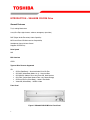
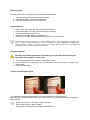
Front Panel
Figure 1.XM-6802B CD-ROM Drive Front Panel

① CD Tray
Insert CD Disc in tray
➁ Busy Indicator
When you install a disc into the CD-ROM drive, the BUSY light flashes
slowly as it attempts to locate the disc. One of the following will occur:
• BUSY light goes out. The CD-ROM drive is ready to read data
from the disc.
• BUSY light flashes slowly. The disc may be dirty.
• BUSY light remains ON. The CD-ROM is accessing data.
• BUSY light remains ON indefinitely. The CD-ROM is
experiencing an error
③ Eject Button
The EJECT button is used to open the disc tray so you can install or
remove a disc
④ Emergency Eject Hole
The emergency eject hole is to be used only when the CD tray will not
open when EJECT button is pressed

3
SETUP – XM-6802B CD-ROM
The following steps must be performed to properly install your drive:
• Set CD-ROM Drive Jumper Settings
• Connect Audio Cable (optional)
• Attach IDE BUS Cable
• Attach Power Cable
• Mount Drive
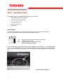
Jumper Settings
The mode select jumpers are 6 straight angle pins located on the rear of the CD-ROM drive.
By placing a jumper on the pins, you can select the following functions:
CS
Drive is configured using host interface signal CSEL
SL Configures drive as Slave
MA Configures drive as Master (default mode)
Figure 1.Mode Select Jumper
In most installations, jumper should remain in the MA position (factory default). It is recommended that
you install your CD-ROM drive only on the secondary IDE BUS. If you are installing on primary IDE BUS,
your hard drive would then be the Master, and you should set your CD-ROM drive to the Slave position
(SL)
Figure 2.Jumper Locations

4
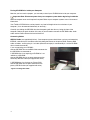
Placing CD-ROM Drive inside your Computer
Now that you have set the jumpers, you are ready to install your CD-ROM drive inside your computer.
Important Note: Disconnect power from your computer system before beginning installation.
Remove computer cover and faceplate if required. Refer to your computer systems manual for removal
information.
Your Toshiba CD-ROM drive can be placed in any free half-height drive slot at the front of your
computer. (It can be mounted horizontally or vertically.)
Carefully start sliding the CD-ROM drive into the opening with the disc tray facing the front of the
computer. Before you push the drive all the way in you will need to connect the IDE BUS cable, Audio
cable and the Power cable on the back of the drive.
Connecting Cables
IDE BUS Cable (not supplied with drive) - Your computer system should have a primary and secondary
IDE BUS, cable with your Hard Drive most likely being the Master on the primary BUS. Connect BUS
cable as follows, assuring that pin 1 of cable (side with red stripe) is connected to pin 1 of the CD-ROM
drive's interface connector:
If you are replacing your CD-ROM :
connect CD-ROM drive to the BUS Cable connector that
the CD-ROM was connected to.
If CD-ROM drive is not replacing a CD-ROM or is an
addition to a CD-ROM:
connect CD-ROM drive to an open connector on the
secondary IDE BUS cable (not supplied with drive).
If CD-ROM drive is to be slave on Primary BUS:
connect CD-ROM drive to open connector on the
primary IDE BUS cable (not supplied with drive).
Figure 3.Installing BUS Cable

5
Power Cable - Connect an internal computer power
supply cable to the power socket at the back of the CD-
ROM drive. One side of the plug has chamfered edges,
so the power connector fits only one way. Push plug
completely into the socket making sure the plug fits
correctly.
Figure 4.Installing Power Cable
Audio Cable (optional) - If you have a sound card and
speakers, and would like to play audio CDs on your
computer, you will need to install a CD audio cable.
Toshiba's CD-ROM drives use a standard 4-pin audio
cable that can be purchased from most local computer
suppliers. The sound cable connects to your sound card
at one end and the other end connects to the digital
audio connector at the left rear of the CD-ROM drive
(see CD-ROM drive Back Panel
photo for location).
Refer to the instructions that came with your sound card
for details on any sound-driver software required
.
Figure 5.Installing Audio Cable
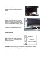
Completing Installation
After you have connected all the necessary cables,
push the CD-ROM drive completely into the
computers drive slot. Mount drive per your computers
instructions. The screw length should not exceed
30.5mm (measured from outside surface of side or
bottom of drive to tip of screw). Replace computer
cover and all outer screws.
Figure 6.Mounting Illustration
Software Driver - Toshiba's optical drives do not require any unique device drivers for Windows
'95/'98/2000/Me/XP/NT. After installing your drive and re-booting, your system should recognize your
drive. Windows '95/'98/2000/Me/XP/NT Operating Systems support all Toshiba optical drives natively If
you prefer using DOS, download the DOS ATAPI driver from our web site.

6
USING THE CD-ROM Drive – XM-6802B
Drive Operation
Inserting a Disc - Horizontally
To insert a disc into a drive that is mounted horizontally, perform the following steps:
Figure 1.Inserting Disc
1. Open the drive's Loading tray by pressing the Eject Button.
2. Place disc into drive's Loading tray
3. Press Eject button again or gently push on the open disc tray. Tray will automatically close.
Inserting a Disc - Vertically
To insert a disc in a drive that is mounted vertically, perform the following steps:
1. Locate sliding disc holders (4 locations) on drive's Loading Tray.
2. Position the disc behind the disc holders
3. Close the drive by gently pushing in the tray or pressing the eject button.
Figure 2.Inserting Disc Vertically

7
Removing a Disc
To remove a disc from the CD-ROM drive, perform the following steps:
1. Open the Loading Tray by pressing the Eject Button.
2. Grasp disc by edges, and lift out of loading tray.
3. Press Eject Button again to close Loading Tray.
Usage Guidelines
• Keep the disc tray closed when not using the CD-ROM Drive.
• Do not press down on the disc tray when opening or closing it.
• Do not place objects on the disc tray.
• Never use a damaged, broken, or deformed disc.
• Do not press the Open/Close button while the computer is accessing a disc.
NOTE: High-speed drives spin the disc at a high rotational speed. If a disc has printing on only half of the
disc, or if there is a slight imbalance in the disc, the imbalance is greatly magnified by the high speed,
causing the drive to vibrate or produce a fan-like noise. These effects are inherent in the high-speed
technology and do not indicate a problem with the drive.
Emergency Ejection
CAUTION: The following procedure is intended only as a last resort when pressing the
eject button fails to open the Loading Tray
1. Turn computer power OFF by properly shutting down system.
2. Insert a solid bar (i.e. large paper clip) into Emergency Eject hole and push as shown in the
picture below
3. CD tray will open/eject.
Figure 3.Using Emergency Eject
This procedure cannot be repeated without cycling the CD-ROMs (computer's) power.
After the media is removed and the loading tray is closed, the tray will not reopen without first turning the
power ON/OFF.
NOTE: Use a bar that is less than 1.5 mm in diameter.
Do not insert more than 50mm in depth.
Inserting more than 50mm may damage the CD-ROM drive.

8
Cleaning Media
Try to avoid touching the read area (underside) of the disc as dirt and smears will degrade the disc
accessing speed.
If the disc becomes dirty wipe it with a damp soft cloth. Avoid cleaning in a circular motion, but rather
from the inner side outward.

9
TROUBLESHOOTING – XM-6802B
Problem
Solution
Disc tray cannot be opened
• Check that there is power to drive.
• Use Emergency Eject instructions to open tray.
Drive is not recognized by system
• Is the drive connected properly? Are all cables plugged in properly (e.g.
Power Cable, Interface Cable and Audio Cables).
• Are the drive configuration jumpers on the CD-ROM drive set properly?
• Is the software driver loaded? On a step-by-step (F8) Boot of the
system is the CD-ROM drive recognized?
(BIOS / DOS reports "device driver not found" or "no valid drivers
selected.). If not, Contact Technical Support.
• Has the CD-ROM drive software driver been corrupted by a virus. Run a
Virus Scan program and repair if possible. Contact Technical Support if
the Virus renders the CD-ROM drive software drivers not useable.
Drive is not recognized by system
during Boot process, but is
recognized by the Operating
System (i.e. XP, Win2000, Win98,
Win NT, etc.)
• Is the CD-ROM drive software driver loaded? On a step-by-step (F8)
Boot of the system is the CD-ROM drive recognized?
(BIOS / DOS reports "device driver not found or no valid drivers
selected.). If not, Contact Technical Support.
• Has the Windows CD-ROM drive software driver program been
corrupted by a virus. Run a Virus Scan program and repair if possible.
Contact Technical Support if the Virus renders the software drivers not
useable.
BUSY Indicator LED flashes
slowly
• The disc may be dirty Clean it with a soft damp cloth. Avoid cleaning the
disc using a circular motion. The disc should be wiped in a radial
direction. That is, from the inner side outward.
• The laser lens may have become cloudy or blocked by particulate
matter. Please contact Technical Support.
BUSY Indicator LED is constantly
ON
• Possible Hardware Problem. Please contact Technical Support.
CD-ROM can not play a CD in the
drive or certain types of CD media
(i.e. CD-plus, etc.)
• Is the CD-ROM drive driver loaded
• Is the CD disc the correct format for the type of system that you are
using? (i.e. on a PC an ISO9660 IBM compatible PC format as opposed
to Apple/Mac HFS disc or UNIX disc formats which will not function).
• Do you have the correct software applications program/drivers installed
to run a CD disc?
• Has the Windows CD-ROM drive software driver program been
corrupted by a virus. Run a Virus Scan program and repair if possible.
Contact Technical Support if the Virus renders the software drivers not
useable.

10
SPECIFICATIONS –XM-6802B
General
Interface ATAPI
Compatible CD-ROM Standards
CD-DA (Red-Book) - Standard Audio CD & CD-Text
CD-ROM (Yellow-Book Mode 1 & 2) - Standard Data
CD-ROM XA (Mode2 Form 1&2) - Photo CD, Multi-Session
CD-I/FMV (Green Book, Mode 2 Form1&2, Ready, Bridge)
CD-Extra/CD-Plus (Blue Book) - Audio & Text/Video
Video-CD (White Book) - MPEG1 Video
Performance
Data Transfer Rate CD-ROM/R Read (mode 1): 7,800 Kbytes/s
CD-RW Read Mode 1) 6,000 Kbytes/s
Transfer Rate
Sustained PIO Host 16.7 Mbyte/s (PIO Mode 4)
Multiple Word DMA 16.7 Mbyte/s (multiple word DMA transfer mode 2)
Ultra DMA 33.3 MByte/s (Ultra DMA)
Access Time 90ms
Memory Buffer 128Kbytes
Audio
Frequency Response 20Hz to 20,000 Hz
Signal-to-noise Ratio 80 dB
Total Harmonic Distortion 0.15% Max
Output Levels 0.725V 0.10%Vrms
Acoustical Noise <54dB
Environmental
Operating 5° to 50° C (41° to 122° F)
Storage -40° to 65° C (-40° to 149° F)
Relative Humidity
Operating 20% to 80%
Storage 5% to 95%

11
Power
DC Voltage and Current Requirements 5V 5%, 12V 10%
Physical
Height 5.83" (148.2mm)
Width 1.65" (42mm)
Depth 7.24" (184mm)
Weight 1.66lbs (740g)
Connectors
DC input AMP 1-480424-0 or equivalent, 2m max
ATAPI Interface Connector 40 Pin ATAPI Standard, 0.46m max length
Analog Audio Line Output Connector 4 Pin ATAPI Standard, 3m max)
Regulatory
The XM-6802B CD-ROM drive has been certified by the following regulatory agencies:
UL 1950
E225119
CAN/CSA C22.2 No. 950
TUV
CE standard
DHHS 21 CFR Sub-Chapter J

12
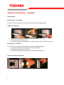
DRIVE CONNECTORS –XM-6802B
Figure 1.XM-6802B CD-ROM Drive Rear Panel - Connectors
Power
Connector
Power is supplied to your CD-ROM drive by the connection with your computer's
+5V/+12V power cable to the power socket at the back of drive. One side of the plug
has chamfered edges, so the power connector fits only one way
CAUTION: Severe damage to the Drive circuits may occur if power cable is plugged in
upside-down with power ON.
Audio
Connectors
Supplies Analog sound to your system
ATAPI
Connector
The XM-6802B CD-ROM drive is connected to your computer system through the ATAPI
connector.

13
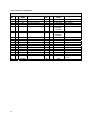
Table 1.Interface Pin Assignments
INTERFACE PIN ASSIGNMENT
PIN
NO.
I/O SIGNAL
NAME
HOST SIGNAL NAME PIN
NO.
I/O SIGNAL
NAME
HOST SIGNAL NAME
1 I Reset Host Reset 21 O HDRQ DMA Request
2 - GND 22 - GND
3 I/O HD7 Host Data Bus BIT 7 23 I HWR-,STOP Host I/O Write
4 I/O HD8 Host Data Bus BIT 8 24 - GND
5 I/O HD6 Host Data Bus BIT 6 25 I HRD-,
HDMARDY, -
HSTROBE
Host I/O Read
6 I/O HD9 Host Data Bus BIT 9 26 - GND
7 I/O HD5 Host Data Bus BIT 5 27 O IORDY,
DDMARDY,-
DSTROBE
I/O Channel Ready
8 I/O HD10 Host Data Bus Bit 10 28 - CSEL Cable Select
9 I/O HD4 Host Data Bus BIT 4 29 I HDAK- DMA Acknowledge
10 I/O HD11 Host Data Bus BIT 11 30 - GND
11 I/O HD3 Host Data Bus BIT 3 31 O INTRQ Host Interrupt Request
12 I/O HD12 Host Data Bus BIT 12 32 O IOCS16- Host 16 BIT I/O
13 I/O HD2 Host Data Bus BIT 2 33 I HA1 Host Address Bus BIT 1
14 I/O HD13 Host Data Bus BIT 13 34 I/O PDIAG- Passed Diagnostics
15 I/O HD1 Host Data Bus BIT 1 35 I HA0 Host Address Bus BIT 0
16 I/O HD14 Host Data Bus BIT 14 36 I HA2 Host Address Bus BIT 2
17 I/O HD0 Host Data Bus BIT 0 37 I HCS1 Host CHIP Select 0
18 I/O HD15 Host Data Bus BIT 15 38 I HCS3 Host CHIP Select 1
19 - GND 39 I/O DASP- Drive Active/Drive 1
Present
20 - (KEYPIN) 40 - GND
-
 1
1
-
 2
2
-
 3
3
-
 4
4
-
 5
5
-
 6
6
-
 7
7
-
 8
8
-
 9
9
-
 10
10
-
 11
11
-
 12
12
-
 13
13
-
 14
14
-
 15
15


Toshiba XM-6802B User manual
- Category
- Optical disc drives
- Type
- User manual
Ask a question and I''ll find the answer in the document
Finding information in a document is now easier with AI
Related papers
-
Toshiba SD-M2012C User manual
-
-
-
-
-
-
-
-
-