

ii
Copyright Notice
The material in this document is the intellectual property of MICRO-STAR
INTERNATIONAL. We take every care in the preparation of this document, but no
guarantee is given as to the correctness of its contents. Our products are under
continual improvement and we reserve the right to make changes without notice.
Trademarks
All trademarks are the properties of their respective owners.
Intel
®
and Pentium
®
are registered trademarks of Intel Corporation.
AMD, Athlon™, Athlon™ XP, Thoroughbred™, and Duron™ are registered trade-
marks of AMD Corporation.
NVIDIA, the NVIDIA logo, DualNet, and nForce are registered trademarks or trade-
marks of NVIDIA Corporation in the United States and/or other countries.
PS/2 and OS
®
/2 are registered trademarks of International Business Machines
Corporation.
Windows
®
98/2000/NT/XP/Vista are registered trademarks of Microsoft Corporation.
Netware
®
is a registered trademark of Novell, Inc.
Award
®
is a registered trademark of Phoenix Technologies Ltd.
AMI
®
is a registered trademark of American Megatrends Inc.
Revision History
Revision Revision History Date
V1.0 First release July 2008
Technical Support
If a problem arises with your system and no solution can be obtained from the user’s
manual, please contact your place of purchase or local distributor. Alternatively,
please try the following help resources for further guidance.
Visit the MSI website at http://global.msi.com.tw/index.php?
func=service for FAQ, technical guide, BIOS updates, driver updates, and
other information.
Contact our technical staff at http://ocss.msi.com.tw.
PDF created with pdfFactory Pro trial version www.pdffactory.com

iii
Safety Instructions
1. Always read the safety instructions carefully.
2. Keep this User’s Manual for future reference.
3. Keep this equipment away from humidity.
4. Lay this equipment on a reliable flat surface before setting it up.
5. The openings on the enclosure are for air convection hence protects the equip-
ment from overheating. DO NOT COVER THE OPENINGS.
6. Make sure the voltage of the power source and adjust properly 110/220V be-
fore connecting the equipment to the power inlet.
7. Place the power cord such a way that people can not step on it. Do not place
anything over the power cord.
8. Always Unplug the Power Cord before inserting any add-on card or module.
9. All cautions and warnings on the equipment should be noted.
10.Never pour any liquid into the opening that could damage or cause electrical
shock.
11. If any of the following situations arises, get the equipment checked by service
personnel:
The power cord or plug is damaged.
Liquid has penetrated into the equipment.
The equipment has been exposed to moisture.
The equipment does not work well or you can not get it work according to
User’s Manual.
The equipment has dropped and damaged.
The equipment has obvious sign of breakage.
12. DO NOT LEAVE THIS EQUIPMENT IN AN ENVIRONMENT UNCONDITIONED, STOR-
AGE TEMPERATURE ABOVE 60
0
C (140
0
F), IT MAY DAMAGE THE EQUIPMENT.
CAUTION: Danger of explosion if battery is incorrectly replaced.
Replace only with the same or equivalent type recommended by the
manufacturer.
PDF created with pdfFactory Pro trial version www.pdffactory.com

iv
FCC-B Radio Frequency Interference Statement
This equipment has been
tested and found to comply
with the limits for a Class B
digital device, pursuant to Part
15 of the FCC Rules. These limits are designed to provide reasonable protection
against harmful interference in a residential installation. This equipment generates,
uses and can radiate radio frequency energy and, if not installed and used in accor-
dance with the instructions, may cause harmful interference to radio communications.
However, there is no guarantee that interference will not occur in a particular
installation. If this equipment does cause harmful interference to radio or television
reception, which can be determined by turning the equipment off and on, the user is
encouraged to try to correct the interference by one or more of the measures listed
below.
Reorient or relocate the receiving antenna.
Increase the separation between the equipment and receiver.
Connect the equipment into an outlet on a circuit different from that to
which the receiver is connected.
Consult the dealer or an experienced radio/television technician for help.
Notice 1
The changes or modifications not expressly approved by the party responsible for
compliance could void the user’s authority to operate the equipment.
Notice 2
Shielded interface cables and A.C. power cord, if any, must be used in order to
comply with the emission limits.
VOIR LA NOTICE D’INSTALLATION AVANT DE RACCORDER AU RESEAU.
Micro-Star International
MS-9826
This device complies with Part 15 of the FCC Rules. Operation is subject to the
following two conditions:
(1) this device may not cause harmful interference, and
(2) this device must accept any interference received, including interference that
may cause undesired operation.
PDF created with pdfFactory Pro trial version www.pdffactory.com


viii
CONTENTS
Copyright Notice....................................................................................................ii
Trademarks............................................................................................................ii
Revision History....................................................................................................ii
Technical Support.................................................................................................ii
Safety Instructions................................................................................................iii
FCC-B Radio Frequency Interference Statement...................................................iv
WEEE (Waste Electrical and Electronic Equipment) Statement................................v
Chapter 1 Product Overview..........................................................................1-1
Mainboard Specifications.............................................................................1-2
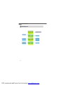
Block Diagram...............................................................................................1-4
Mainboard Layout........................................................................................1-5
Board Dimension..........................................................................................1-6
Back Panel & I/O Shield Drawing..................................................................1-7
Power Consumption....................................................................................1-8
Safety Compliance & MTBF..........................................................................1-9
Chapter 2 Hardware Setup.............................................................................2-1
Quick Components Guide.............................................................................2-2
CPU (Central Processing Unit)......................................................................2-3
Memory.......................................................................................................2-6
Power Supply..............................................................................................2-7
Back Panel...................................................................................................2-8
Connector....................................................................................................2-9
Jumper......................................................................................................2-13
Slot............................................................................................................2-14
Chapter 3 BIOS Setup......................................................................................3-1
Entering Setup.............................................................................................3-2
The Menu Bar..............................................................................................3-4
Main.............................................................................................................3-5
Advanced....................................................................................................3-6
PCIPnP.......................................................................................................3-16
Boot...........................................................................................................3-17
Security.....................................................................................................3-19
Chipset......................................................................................................3-20
Power........................................................................................................3-24
Exit............................................................................................................3-25
Chapter 4 System Resources.......................................................................4-1
Watch Dog Timer Setting..............................................................................4-2
AMI POST Code...........................................................................................4-3
Resource List..............................................................................................4-6
PDF created with pdfFactory Pro trial version www.pdffactory.com

1-1
Product Overview
Chapter 1
Product Overview
Thank you for choosing the AM-690E (MS-9826 v1.X)
Mini ITX mainboard from MSI.
Based on the innovative AMD
®
RS690E & SB600 con-
trollers for optimal system efficiency, the AM-690E ac-
commodates the latest AMD
®
Sempron, Athlon 64/64
X2 (Dual Core) processors in Socket AM2 and sup-
ports two DDR2 533/667/800 DIMM slots to provide the
maximum of 4GB memory capacity.
In the entry-level and mid-range market segment, the
AM-690E can provide a high-performance solution for
today’s front-end and general purpose workstation, as
well as in the future.
PDF created with pdfFactory Pro trial version www.pdffactory.com

MS-9826 Mainboard
1-2
Mainboard Specifications
Processor
- AMD Sempron, Athlon 64/64 X2 (Dual Core) processor in Socket AM2
- 4-pin CPU fan pinheader with Smart Fan Speed Control
FSB
- Hyper Transport supporting speed up to 1 GHz (2000MT/s)
Chipset
- Northbridge: AMD RS690E
- Southbridge: AMD SB600
Memory
- Unbuffered ECC DDR2 533/667/800 SDRAM (4GB Max)
- 2 DDR2 DIMM slots (240pin / 1.8V)
LAN
- Supports Gigabit Ethernet by Marvell 88E8056
IDE
- 1 IDE port by AMD SB600
- Supports Ultra DMA 66/100/133 mode
- Supports PIO, Bus Master operation mode
SATA
- 2 SATA II ports by AMD SB600
- Supports storage and data transfers at up to 3Gb/s
Slot
- 1 32-bit/33MHz PCI slot
Connectors
Back Panel
- 2 RJ-45 Gigabit LAN jacks
- 4 USB 2.0 ports
- 1 serial port
- 1 D-Sub VGA connector
- 1 PS/2 keyboard port
- 1 PS/2 mouse port
PDF created with pdfFactory Pro trial version www.pdffactory.com

1-3
Product Overview
Onboard Connectors
- 1 SPI Flash ROM connector (for debugging)
- 1 chassis intrusion switch connector
- 1 SMBus connector
- 1 front panel connector
- 1 CPU fan connector
- 1 system fan connector
- 2 SATA connectors
Form Factor
- Mini ITX: 170mm x 170mm
Mounting
- 4 mounting holes
Environmental
Storage Temperature
- Temperature: -20
o
C ~ 80
o
C
- Humidity: 0% RH ~ 95% RH
Operation Temperature
- Temperature: 0
o
C ~ 60
o
C
- Humidity: 0% RH ~ 85% RH
PDF created with pdfFactory Pro trial version www.pdffactory.com


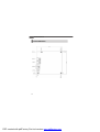
1-5
Product Overview
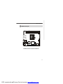
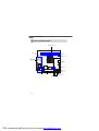
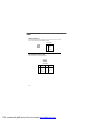
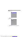
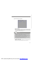
AM-690E (MS-9826 v1.X) Mini ITX Mainboard
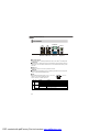
Mainboard Layout
PCI1
DIMM1
DIMM2
JSPI1
SATA1
JBAT1
IDEB1
J1
JPW1
SATA2
JFP1
SYSFAN1
CPUFAN1
B
A
T
T
+
Top: Mouse
Bottom: Keyboard
Top: LAN Jack
Bottom: USB Ports
Top: LAN Jack
Bottom: USB Ports
Top:
Serial Port
Bottom:
VGA Port
HDPWR1
JCASE1
AMD
RS690E
AMD
SB600
PDF created with pdfFactory Pro trial version www.pdffactory.com


MS-9826 Mainboard
1-8
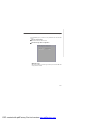
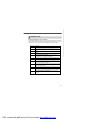
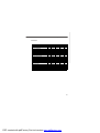
Power Consumption
Component
CPU AMD Athlon™ 64 x2 Dual Core 2G
DDR2
HDD
ODD NEC DVD-Multi Record ND-4550A
Description
1024MB DDR2 533 *2
Maxtor 80G
12Vp 12V 5V 3.3V 5VSB -12V W
AMD ThermNow! Utility 4.2 0.81 3.03 1.08 0.032 0.028 79.33
Particle Fuly + VCD + Xcopy 3.07 1.01 4.66 1.07 0.039 0.02 76.226
3Dmark 2005 2.81 0.84 4.27 1.06 0.04 0.042 69.352
Idle 0.82 0.81 3.09 1.17 0.024 0.017 39.195
S3 0 0 0 0 0.512 0 2.56
PDF created with pdfFactory Pro trial version www.pdffactory.com

1-9
Product Overview
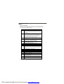
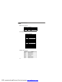
MTBF - Reliability Prediction
Safety Compliance & MTBF
Certification Title of standard
EN 55022:1998+A1:2000+A2:2003 Class BProduct family standard
EN 6100-3-2:2000 Class D
Limits for harmonic current
emission
EN 6100-3-3:1995+A1:2001
Limitation of voltage
fluctuation and flicker in low-
voltage supply system
ImmunityEN 55024:1998+A1:2001+A2:2003 Product family standard
BSMI
C-Tick
CE
RFI
VCCI
VCCI V-3:2004, Class B
VCCI V-4:2004, Class B
Standard number
FCC
AS/NZS CISPR 22:2004
CNS 13438 乙類(1997年版)
FCC CFR Title 47 Part 15 Subpart B: 2005 Class B
CISPR 22: 2005
Calculation Model
Operation
Temperature (°C)
Operation
Environment
Duty CycleMTBF (hr.)
Telcordia Issue 1 40
GB, GC - Ground
Benign,
Controlled
4,892.341404 204,401
PDF created with pdfFactory Pro trial version www.pdffactory.com


2-1
Hardware Setup
Chapter 2
Hardware Setup
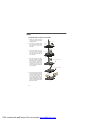
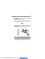
This chapter provides you with the information about
hardware setup procedures. While doing the installation,
be careful in holding the components and follow the
installation procedures. For some components, if you
install in the wrong orientation, the components will not
work properly.
Use a grounded wrist strap before handling computer
components. Static electricity may damage the
components.
PDF created with pdfFactory Pro trial version www.pdffactory.com

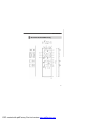
2-2
MS-9826 Mainboard
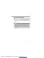
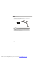
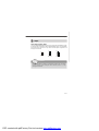
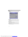
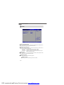
Quick Components Guide
SYSFAN1, p.2-11
CPU, p.2-3
DIMM Slots, p.2-6
IDEB1, p.2-9
Back Panel
I/O, p.2-8
CPUFAN1, p.2-11
HDPWR1,
p.2-7
SATA1~2, p.2-10
JPW1, p.2-7
J1, p.2-12
PCI Slot, p.2-14
JBAT1, p.2-13
JSPI1, p.2-12
JCASE1, p.2-9
JFP1, p.2-11
PDF created with pdfFactory Pro trial version www.pdffactory.com
Page is loading ...
Page is loading ...
Page is loading ...
Page is loading ...
Page is loading ...
Page is loading ...
Page is loading ...
Page is loading ...
Page is loading ...
Page is loading ...
Page is loading ...
Page is loading ...
Page is loading ...
Page is loading ...
Page is loading ...
Page is loading ...
Page is loading ...
Page is loading ...
Page is loading ...
Page is loading ...
Page is loading ...
Page is loading ...
Page is loading ...
Page is loading ...
Page is loading ...
Page is loading ...
Page is loading ...
Page is loading ...
Page is loading ...
Page is loading ...
Page is loading ...
Page is loading ...
Page is loading ...
Page is loading ...
Page is loading ...
Page is loading ...
Page is loading ...
Page is loading ...
Page is loading ...
Page is loading ...
Page is loading ...
Page is loading ...
Page is loading ...
Page is loading ...
Page is loading ...
Page is loading ...
Page is loading ...
Page is loading ...
-
 1
1
-
 2
2
-
 3
3
-
 4
4
-
 5
5
-
 6
6
-
 7
7
-
 8
8
-
 9
9
-
 10
10
-
 11
11
-
 12
12
-
 13
13
-
 14
14
-
 15
15
-
 16
16
-
 17
17
-
 18
18
-
 19
19
-
 20
20
-
 21
21
-
 22
22
-
 23
23
-
 24
24
-
 25
25
-
 26
26
-
 27
27
-
 28
28
-
 29
29
-
 30
30
-
 31
31
-
 32
32
-
 33
33
-
 34
34
-
 35
35
-
 36
36
-
 37
37
-
 38
38
-
 39
39
-
 40
40
-
 41
41
-
 42
42
-
 43
43
-
 44
44
-
 45
45
-
 46
46
-
 47
47
-
 48
48
-
 49
49
-
 50
50
-
 51
51
-
 52
52
-
 53
53
-
 54
54
-
 55
55
-
 56
56
-
 57
57
-
 58
58
-
 59
59
-
 60
60
-
 61
61
-
 62
62
-
 63
63
-
 64
64
-
 65
65
-
 66
66
-
 67
67
-
 68
68


Ask a question and I''ll find the answer in the document
Finding information in a document is now easier with AI
Related papers
Other documents
-
 iiView 750PDVX User manual
-
Electrolux END33500X User manual
-
Sylvania SYTAB10MT User manual
-
Foxconn 761GXK8MC User manual
-
Audiovox DPF702 - Digital Photo Frame User manual
-
Craig CMP837 BUN Owner's manual
-
 iiView 102DV User manual
-
Intel IM-Q35 Series User manual
-
Maruyama MSD41 Operating instructions
-
Medion ms-7501M1 User manual

