Page is loading ...

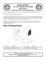
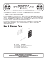
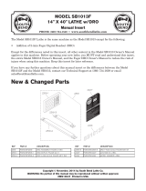
Model SB1037F
Page 1 of 4
Model SB1037F
South Bend 16" x 40" Lathe 220V with DRO
Product Dimensions
Weight........................................................................................................................................................... 3107 lbs.
Width (side-to-side) x Depth (front-to-back) x Height.....................................................................
86 x 33 x 60 in.
Footprint (Length x Width).................................................................................................................
82 x 19-1/2 in.
Shipping Dimensions
Type.................................................................................................................................................. Wood Slat Crate
Content.......................................................................................................................................................... Machine
Weight........................................................................................................................................................... 3374 lbs.
Length x Width x Height....................................................................................................................
94 x 45 x 69 in
Electrical
Power Requirement.................................................................................................................
220V, 3-Phase, 60 Hz
Full-Load Current Rating................................................................................................................................. 21.7A
Minimum Circuit Size.......................................................................................................................................... 30A
Inverter Type............................................................................................................................... Yaskawa G7A25P5
Switch.................................................................................................................
Magnetic with Thermal Protection
Switch Voltage....................................................................................................................................................
220V
Plug Included.......................................................................................................................................................... No
Recommended Plug/Outlet Type.................................................................................................................... L15-30
Motors
Main
Type........................................................................................................................................ TEFC Induction
Horsepower.........................................................................................................................................
7-1/2 HP
Voltage......................................................................................................................................................
220V
Phase.................................................................................................................................................... 3-Phase
Amps........................................................................................................................................................... 20A
Speed.......................................................................................................................................... 0 – 4500 RPM
Cycle.........................................................................................................................................................
60 Hz
Number of Speeds...............................................................................................................................
Variable
Power Transfer ......................................................................................................................... V-Belt & Gear
Bearings.................................................................................................... Shielded and Permanently Sealed

Model SB1037F
Page 2 of 4
Lubrication
Type........................................................................................................................................ TEFC Induction
Horsepower............................................................................................................................................ 1/4 HP
Voltage......................................................................................................................................................
220V
Phase....................................................................................................................................................
3-Phase
Amps.......................................................................................................................................................... 1.4A
Speed................................................................................................................................................ 1725 RPM
Cycle......................................................................................................................................................... 60 Hz
Number of Speeds...........................................................................................................................................
1
Power Transfer ............................................................................................................................
Direct Drive
Bearings.................................................................................................... Shielded and Permanently Sealed
Coolant
Type........................................................................................................................................ TEFC Induction
Horsepower............................................................................................................................................ 1/8 HP
Voltage......................................................................................................................................................
220V
Phase....................................................................................................................................................
3-Phase
Amps.......................................................................................................................................................... 0.3A
Speed................................................................................................................................................ 3450 RPM
Cycle......................................................................................................................................................... 60 Hz
Number of Speeds...........................................................................................................................................
1
Power Transfer ............................................................................................................................
Direct Drive
Bearings.................................................................................................... Shielded and Permanently Sealed
Main Specifications
Operation Info
Swing Over Bed.................................................................................................................................. 16.14 in.
Distance Between Centers...................................................................................................................... 40 in.
Swing Over Cross Slide....................................................................................................................
10.375 in.
Swing Over Saddle.............................................................................................................................
15.67 in.
Swing Over Gap.................................................................................................................................. 22.95 in.
Maximum Tool Bit Size........................................................................................................................ 0.75 in.
Compound Travel.................................................................................................................................... 5.1 in.
Carriage Travel...................................................................................................................................
38.58 in.
Cross Slide Travel.................................................................................................................................
9.25 in.
Headstock Info
Spindle Bore...................................................................................................................................... 2.0625 in.
Spindle Taper.......................................................................................................................................... MT#6
Number of Spindle Speeds................................................................................................................. Variable
Spindle Speeds.........................................................................................................................
20 – 2500 RPM
Spindle Type..............................................................................................................................
D1-6 Camlock
Spindle Bearings................................................................................................ NSK or NTN Tapered Roller
Spindle Length.................................................................................................................................... 24.24 in.
Spindle Length with 3-Jaw Chuck.................................................................................................... 30.31 in.
Spindle Length with 4-Jaw Chuck....................................................................................................
34.08 in.
Spindle Nose to Gap...............................................................................................................................
6.5 in.
Tailstock Info
Tailstock Quill Travel................................................................................................................................ 6 in.
Tailstock Taper........................................................................................................................................ MT#4
Tailstock Barrel Diameter.................................................................................................................. 2.047 in.

Model SB1037F
Page 3 of 4
Threading Info
Number of Longitudinal Feeds..................................................................................................................... 17
Range of Longitudinal Feeds................................................................................................ 0.002 – 0.067 in.
Number of Cross Feeds.................................................................................................................................
17
Range of Cross Feeds.............................................................................................................
0.001 – 0.034 in.
Number of Inch Threads............................................................................................................................... 45
Range of Inch Threads..................................................................................................................... 2 – 72 TPI
Number of Metric Threads........................................................................................................................... 39
Range of Metric Threads..............................................................................................................
0.2 – 14 mm
Number of Modular Pitches..........................................................................................................................
18
Range of Modular Pitches............................................................................................................ 0.3 – 3.5 MP
Number of Diametral Pitches....................................................................................................................... 21
Range of Diametral Pitches.............................................................................................................. 8 – 44 DP
Dimensions
Bed Width..........................................................................................................................................
10-1/4 in.
Leadscrew Diameter............................................................................................................................
1-1/8 in.
Leadscrew TPI................................................................................................................................................. 4
Leadscrew Length............................................................................................................................... 63.58 in.
Steady Rest Capacity............................................................................................................. 5/16 – 4-5/16 in.
Follow Rest Capacity..................................................................................................................
5/8 – 3-1/8 in.
Faceplate Size..........................................................................................................................................
12 in.
Feed Rod Diameter................................................................................................................................. 3/4 in.
Floor to Center Height...................................................................................................................... 43-1/2 in.
Height With Leveling Jacks.............................................................................................................. 44-1/2 in.
Construction
Base....................................................................................................................................................
Cast Iron
Headstock..........................................................................................................................................
Cast Iron
Headstock Gears.......................................................................................................... Flame Hardened Steel
Bed.............................................................................................. Induction Hardened and Ground Cast Iron
Stand.................................................................................................................................................. Cast Iron
Other
Country Of Origin ..............................................................
Taiwan (Some Components Made in USA and Japan)
Warranty .........................................................................................................................................................
1 Year
Serial Number Location .................................................................................
ID Label on Rear Side of Left Stand
Assembly Time ......................................................................................................................
Approximately 1 Hour
Features
Allen Bradley Electrical Components
Fagor DRO
Meehanite Casting, Signature South Bend 3 V-Way Bed
Safety Chuck Guard with Micro-Switch Shut-Off
Halogen Work Light
4-Way Tool Post
Complete Coolant System
Micrometer Carriage Stop
Threading Dial Indicator
NSK or NTN Japanese Spindle Bearings
Full Length Splash Guard
Front Removable Sliding Chip Tray
Yaskawa G7A25P5 Inverter
Completely Enclosed Universal Gearbox for Cutting Inch, Metric, Modular and Diametral Pitches
Pressurized Lubrication System for Headstock Gears and Bearings
Dial Controlled, Variable Spindle Speeds with Digital Read Out
Jog Button and Emergency Stop

Model SB1037F
Page 4 of 4
Included Accessories
9 in. 3-Jaw Scroll Chuck Mounted to 9 in. D1-6 Back Plate
10 in. D1-6 Back Plate 10 in. 4-Jaw Independent Chuck D1-6
12 in. Faceplate D1-6
Follow Rest
Steady Rest with Roller Bearing Tips
#6 to #4 Morse Taper Spindle Sleeve
Two Morse Taper #4 Dead Centers (1 Carbon Steel and 1 Carbide-Tipped)
Eight Leveling Pads
Service Tools
Tool Box
USA Written Manual
/