Masterpage:Right+
Filename [TH-R1R3EU_05Name.fm]
Page 8Monday, 28 March 2005 21:23
INDEX
8
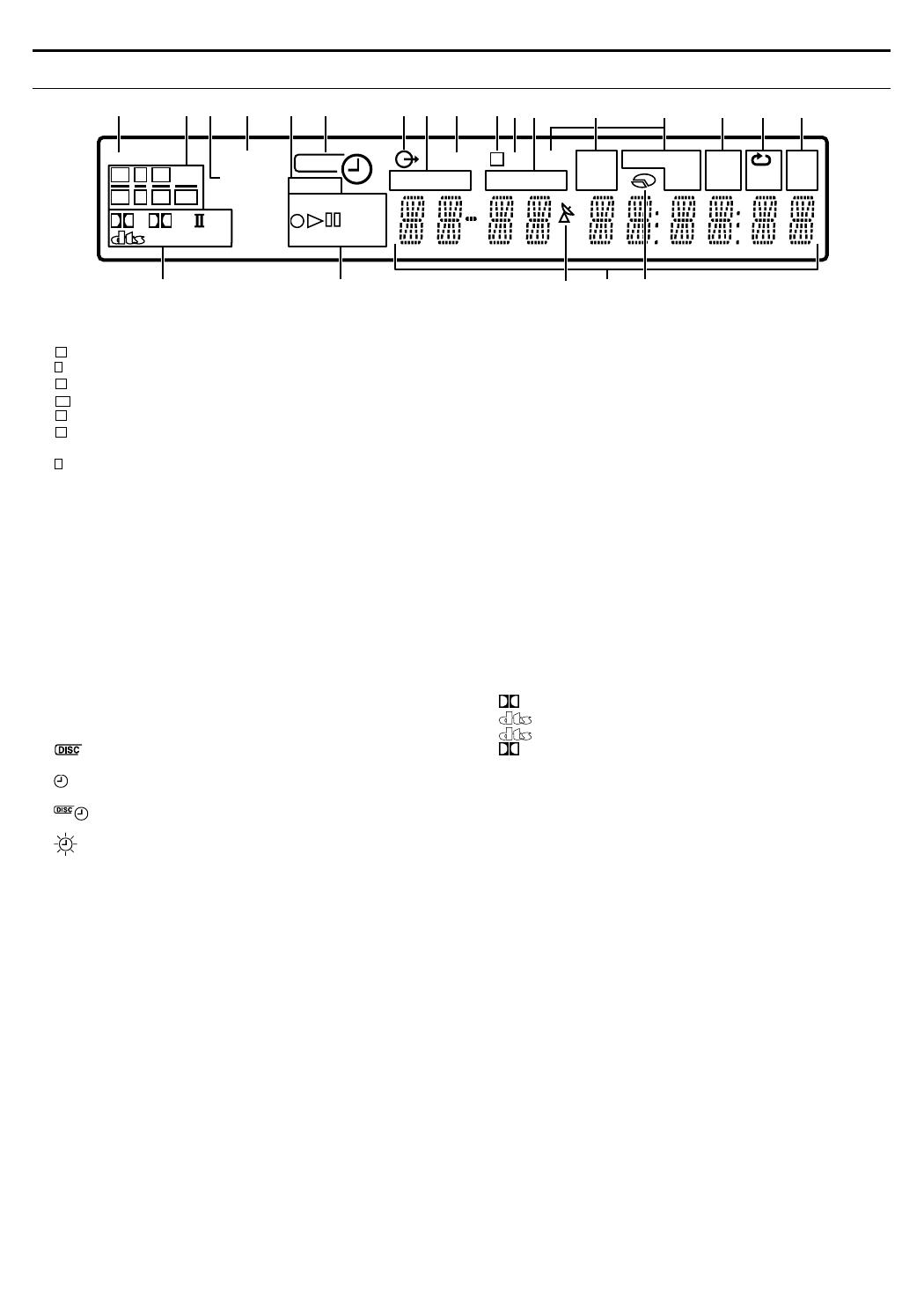
Front Display Panel
A TV DIRECT Indicator A pg. 31
B Source signal indicators, etc.
Light to indicate the incoming signals.
: Lights when the left channel signal is detected.
: Lights when the centre channel signal is detected.
: Lights when the right channel signal is detected.
: Lights when the LFE channel signal is detected.
: Lights when the left surround channel signal is detected.
: Lights when the right surround channel signal is
detected.
: Lights when the monaural surround channel signal or 2
channel Dolby Surround signal is detected.
ASWB : Always lights except during HEADPHONE and TV
DIRECT mode.
The channel with A__B shows that the corresponding speakers
are reproducing the channels’ sound.
If the channels’ sound decoded into 5.1 channel is reproduced,
only A__B lights.
C RESUME Indicator A pg. 29
Lights when resume is set.
D VPS/PDC Indicator A pg. 50
Lights when checking if the station being received transmits a
VPS/PDC signal.
E VR/DV Indicator A pg. 65
AVRB : Lights when a DVD-RW disc formatted in VR mode is
loaded.
ADVB : Lights when DV channel is being selected.
F DISC Timer Indicator A pg. 51
: Lights when a disc set up for On-Disc Timer
Programming is loaded.
: Lights when timer recording other than On-Disc Timer
Programming is on stand-by or being executed.
: Lights when On-Disc Timer Programming is on stand-by
or being executed.
: Blinks quickly if you press TIMERj in the following
cases;
● Disc is not loaded.
● Clock has not been set.
● There is no programme setting.
G Video Indicator (z) A pg. 25
Lights when video mode is selected by pressing TV/VIDEO.
H GRP/TITLE Indicator
Indicates the group (GRP) and title (TITLE) being played back.
The number being played back is displayed on the Multi Display.
I TUNED Indicator A pg. 44
Lights when a radio station with sufficient signal strength is tuned.
J Video Output Indicator (q) A pg. 77
No display: Indicates that interlace mode is engaged.
q: Indicates that progressive mode is engaged.
(Example) q lights when video output mode is in progressive
mode.
K ST Indicator A pg. 44
Lights during FM STEREO reception.
L TRK/CHAP. Indicator
Indicates the track (TRK) and chapter (CHAP) being played back.
The number being played back is displayed on the Multi Display.
M AUTO MUTE Indicator A pg. 44
Lights when FM mode is in the auto muting mode.
N Radio Data System Indicator A pg. 47
ARDSB : Lights when the RDS service of a FM station is
being received.
ATA B : Traffic Announcement in your area.
ANEWSB :News.
AINFOB : Programme the purpose of which is to impart
advice in the widest sense.
O PRG/RND Indicator A pg. 38
APRGB : Lights when Programme Playback mode is set.
ARNDB : Lights when Random Playback mode is set.
P Repeat Mode Indicator (x/1/A-B) A pg. 35, 36
Select Repeat Playback mode on the on-screen bar.
AxB : Whole disc is played back repeatedly.
Ax 1B : A single title/chapter/track is played back
repeatedly.
Ax A-BB : The selected part (A-B) is played back
repeatedly.
No display : Repeat Playback mode is off.
Q Frequency Indicator A pg. 44
AkHzB lights during AM reception.
AMHzB lights during FM reception.
R Digital Sound Type/Dolby Surround and DSP mode
Indicators A pg. 42
D : Lights when Dolby Digital sound is being played.
: Lights when DTS sound is being played.
96/24 : Lights when DTS96/24 sound is being played.
PL II : Lights during Dolby Pro Logic II mode.
ADSPB : Lights during All Channel Stereo mode or DAP
mode (A pg. 43).
S Disc Type Indicator
When a disc is loaded, the type of the disc (DVD-RAM, -R, -RW,
VCD, CD) is indicated.
Recording Mode Indicator (XP/SP/LP/EP/FR) A pg. 39
Disc Status Indicator A pg. 25, 39
R:While recording
I: During Playback
W: While paused
T Automatic Satellite Programme Recording Indicator
A pg. 54
Lights when the unit is in the Auto Satellite Programme
Recording standby mode.
U Multi Display
Displays clock, received channel, elapsed time, remaining time,
GRP, TITLE, TRK, CHAP etc.
Also displays status of the unit.
V Remaining Time/Elapsed Time Display A pg. 30, 40
Lights when remaining time of DVD-RAM, DVD-R and DVD-RW
discs is displayed, and lights out when elapsed time is
displayed.
No display: Indicates elapsed time of the disc.
Displayed: Indicates remaining time of the disc.
MHz
kHz
A-B
1
RND
PRG
INFO
TA
NEWS
MUTE
AUTO
CHAP.
CH
RDS
TRK
ST
TITLE
TUNED
GRP
DISC
VR
XP SP LP EP FR
DVD-RAMW
D
96/24 DSP
PL
RESUME
VPS /PDC
TV DIRECT
VCD
DV
P
L R
SW
C
LS RS LFES
BADCE HF GI
JK
N O P QL
R
T
U
M
S
V
L
C
R
LFE
LS
RS
S
TH-R1R3EU_00.book Page 8 Monday, March 28, 2005 9:23 PM