
Please read and understand all instructions before use. Retain this manual for future reference.
V 3.05 8474116
User Manual
20 Gallon Pressure
Abrasive Blaster

2 For technical questions call 1-800-665-8685
V 3.05 8474116
20 Gallon Pressure
Abrasive Blaster
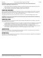
SPECIFICATIONS
Type
Pressure Abrasive Blaster
Operating Pressure
60 to 125 PSI
Air Consumption
6 to 25 CFM
Media Capacity
20 gallons
Features
5 in. rubber wheels for ease of portability
8 ft. hose length
Includes 2, 2.5, 3 and 3.5 mm nozzles
Applications
Can be used with most types of blasting abrasives to remove
paint, scale, rust or graffiti quickly and easily.
IMPORTANT SAFETY PRECAUTIONS
WARNING! Read and understand all instructions before using this tool. The operator must follow basic
precautions to reduce the risk of personal injury and / or damage to the equipment. Before allowing someone
else to use this tool, make sure they are aware of all safety information.
WARNING! The warnings, cautions and instructions discussed in this instruction manual cannot cover all
possible conditions and situations that may occur. Common sense and caution are factors that cannot be built
into this product, but must be supplied by the operator.
NOTE: Keep this manual for the safety warnings, precautions and operating, inspection and maintenance
instructions. When this manual refers to a part number, it refers to the included parts list.
WORK AREA
1. Operate in a safe work environment. Keep your work area clean and well lit.
2. Do not use in the presence of flammable gases or liquids.
3. Keep anyone not wearing the appropriate safety equipment away from the work area.
NOTE: Minimize distractions in the work environment. Distractions can cause you to lose control of
the tool.
4. Store tools properly in a safe and dry location to prevent rust or damage.
5. Always lock up tools and keep them out of the reach of children.
PERSONAL SAFETY
CAUTION! Wear protective equipment approved by the Canadian Standards Association (CSA) or American
National Standards Institute (ANSI) when using the tool.
1. Dress properly; wear protective equipment. Use breathing, ear, eye, face, foot, hand and head protection.
Always wear ANSI approved impact safety goggles, which must provide both frontal and side protection.
Protect your hands with suitable gloves. Wear a full face shield if your work creates metal filings or wood
chips. Protect your head from falling objects by wearing a hard hat. Wear an ANSI approved dust mask

Visit www.princessauto.com for more information 3
8474116 V 3.0520 Gallon Pressure Abrasive Blaster
or respirator when working around metal, wood and chemical dusts and mists. Wear ANSI approved
earplugs. Protective, electrically non-conductive clothes and non-skid footwear are recommended when
working. Wear steel-toed boots to prevent injury from falling objects.
2. Control the tool, personal movement and the work environment to avoid personal injury or damage to the
tool. Stay alert, watch what you are doing and use your common sense.
a. Keep articles of clothing, jewelry, hair, etc., away from moving parts to avoid entanglement with a tool.
b. Do not operate any machine / tool when tired or under the influence of drugs, alcohol or medications.
c. Do not overreach when operating a tool. Proper footing and balance enables better control of a tool in
unexpected situations.
d. Use clamps or other practical ways to support or secure the work piece to a stable platform. Holding
the work piece by hand or against your body is not stable and may lead to loss of control and injury.
SPECIFIC SAFETY PRECAUTIONS
1. When using the tool, wear clothing that is washable to remove the fine dust created during the blasting
process. Disposable protective clothing is also recommended.
2. Wear protective face gear such as goggles, a face shield, a dust mask that will filter out the fine dust
particles created during the abrasive blasting process, ear protection to reduce or eliminate the noise level
and heavy duty gloves to protect your hands.
3. Maintain proper ventilation in the work area. Test the air quality to ensure that exposure to the fine dust
created during the blasting process is lessened.
4. Do not exceed the maximum 125 PSI rating.
5. Use only abrasives specifically intended for blasting.
6. Disconnect the unit from the air source when not in use or before performing any maintenance
or inspections.
7. When searching for leaks, use water with soap to spray onto the unit. Do not use your hands to search for
leaks in a pressurized system.
ABRASIVE BLASTING MEDIA PRECAUTIONS
The blasting process emits abrasive media under pressure that breaks apart upon impact. The resulting dust is a
combination of the media and the material being removed by the abrasive. Both the media and the material being
removed may have toxic components such as lead in paint.
1. Check the abrasive media’s Material Safety Data Sheet (MSDS) for information on the health risks and
preventative measure that can be taken to minimize those risks.
2. Determine the toxicity of the material being removed and take appropriate measures.
3. Work in a well-ventilated area whenever possible or use containment methods such as cabinets or blast-
cleaning machines to control the hazards from exposure.
4. Wear NIOSH approved respirators that protect both the lower face and eyes during blasting operations
whenever possible.
WARNING! Sand or silica particle dust can result in the lung disease known as silicosis, when inhaled over
a short period of time. Silicosis causes shortness of breath, cough, fever and bluish skin (cyanosis). Seek
immediate medical attention if these symptoms appear.
AIR TOOL PRECAUTIONS
1. Extended exposure to air tool noise may cause hearing loss. Ear protection gear can reduce or eliminate
the noise level.
2. Inspect the tool’s airline for cracks, fraying or other faults before each use. Discontinue use if the airline is
damaged or hissing is heard from the airline or connectors, while operating the tool. Replace the defective
component/air line.

4 For technical questions call 1-800-665-8685
V 3.05 847411620 Gallon Pressure Abrasive Blaster
3. Do not allow people, mobile equipment or vehicles to pass over the unprotected air line. Position the
airline away from high traffic areas, in a reinforced conduit or place planks on both sides of the airline to
create a protective trench.
4. Prevent damage to the air line by observing the following:
a. Never carry the tool by the air line.
b. Keep the air line behind the tool and out of the tool’s work path.
c. Keep the air line away from heat, oil, sharp edges or moving parts.
d. Do not wrap the air line around the tool as sharp edges may pierce or crack the airline. Coil the airline
when storing.
5. A damaged or disconnected air line under pressure may whip around and inflict personal injury or damage
the work area. Secure the compressor’s air line to a fixed or permanent structure with clamps or cable ties.
6. Install an in-line shutoff valve or regulator to allow immediate control over the air supply in an emergency,
even if a hose is ruptured.
VIBRATION PRECAUTIONS
This tool vibrates during use. Repeated or long-term exposure to vibration may cause temporary or permanent
physical injury, particularly to the hands, arms and shoulders.
1. Anyone using vibrating tools regularly or for an extended period should first be examined by a doctor and
then have regular medical check-ups to ensure medical problems are not being caused by or worsened
from tool use. Pregnant women or people who have impaired blood circulation to the hands, past hand
injuries, nervous system disorders, diabetes or Raynaud’s Disease should not use this tool. If you feel
any medical symptoms related to vibrations (such as tingling, numbness, and white or blue fingers), seek
medical attention as soon as possible.
2. Do not smoke during use. Nicotine reduces the blood flow to the hands and fingers, increasing the risk of
vibration-related injury.
3. Wear suitable gloves to reduce the vibration effects on the user.
4. Use tools with the lowest amount of vibration when there is a choice between different processes.
5. Do not use for extended periods. Take frequent breaks when using this tool.
6. Let the tool do the work. Grip the tool as lightly as possible (while still keeping safe control of it).
7. To reduce vibrations, maintain the tool as explained in this manual. If abnormal vibrations occur, stop
using this tool immediately.
TOOL USE AND CARE
WARNING! Do not use the tool if the trigger or ON / OFF switch does not function properly. Any tool that cannot
be controlled with the ON / OFF switch is dangerous and must be repaired.
1. Use the correct tool for the job. Maximize tool performance and safety by using the tool for its
intended task.
2. Do not modify this tool or use for a purpose for which it was not designed.
3. This tool / device was designed for a specific function.
Do Not:
a. Modify or alter the tool; all parts and accessories are designed with built-it safety features that may be
compromised if altered.
b. Use the tool in a way for which it was not designed.
4. Avoid unintentional starts. Be sure the trigger is in the neutral position when not in use and before
connecting it to any air source.
5. Maintain the tool with care (see Maintenance).

Visit www.princessauto.com for more information 5
8474116 V 3.0520 Gallon Pressure Abrasive Blaster
ABRASIVE BLASTING MEDIA
There are a number of different abrasive media the tool can use as an abrasive. Each type of abrasive has a
different application and effect on the object being blasted. Each abrasive may also have hazards or health issues
associated with their use.
NOTE: Read the abrasive blasting media precautions section before use and consult the Material Safety Data Sheet
for each abrasive media product.
Material types:
1. Mineral: Sand or silica, garnet, magnesium sulphate.
NOTE: Sand should be avoided, as there are other abrasives that perform the same or better without the
detrimental health effects.
2. Organic: Crushed nutshells.
3. Synthetic: Baking soda, grain starch.
4. Engineered: Aluminum oxide, glass beads.
5. Metal: Shot or grit made from steel, copper, aluminum or zinc.
Recommended Abrasive Blasting Media:
1. Aluminum Oxide
2. Glass Bead
3. Steel Shot
4. Copper Slag
Not Recommended Abrasive Blasting Media:
These blasting medias clog easier and require different nozzles and higher pressures.
1. Baking soda, grain starch
2. Crushed nutshells
NOTE: Store abrasive in a dry location. Wet abrasive will clog the tool.
UNPACKING
1. Carefully remove the tool from the package.
a. Retain packing material until you have carefully inspected and satisfactorily installed or operated
the tool.
2. Make sure that all items in the parts list are included.
3. Inspect the parts carefully to make sure the product was not damaged
while shipping.
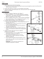
ASSEMBLY
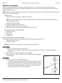
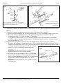
1. Assemble the intake manifold (See figure 1):
a. Attach the pressure gauge (15) to the top of the intake manifold (14),
turning the gauge so that it can be seen across the top of the tank.
b. Attach the brass shut-off valve (18A) to the bottom of the manifold.
c. Attach the threaded bushing (20) to the brass shut-off valve (18).
d. Attach the joint pipe (13) to the manifold (14).
Fig. 1

6 For technical questions call 1-800-665-8685
V 3.05 847411620 Gallon Pressure Abrasive Blaster
2. Assemble the water separator filter (See figure 2):
a. Screw the two threaded bushings (16) into each side
of the water separator filter (17).
b. On the inlet side, attach the brass air supply valve (18) to the
threaded bushing (16).
c. Then attach the threaded bushing (19) to the other side
of the air supply valve.
d. When you are ready to operate the abrasive blaster,
the air hose from the compressor will fasten to the
threaded bushing (19).
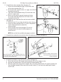
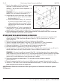
3. Attaching the water separator filter and the intake manifold
(See figure 3):
a. Place the tank (01) on a table with the four clips facing up.
b. Screw the water separator filter (17) and its components
into the hole located on the side of the
intake manifold.
c. Screw the open end of the joint pipe (13) into the
threaded hole on the side of the filler pipe on the
top of the tank.
NOTE: Be sure that the manifold and gauge are vertical.
4. Assemble the sand outlet valve into the hole at the bottom of the tank (See figure 4).
Fig. 3
Fig. 2
Fig. 4 Fig. 5
Attach the four parts in order: threaded bushing (16),
steel shut-off valve (18B), threaded bushing (16) and
the abrasive outlet manifold (22).
5. Assemble the deadman valve and ceramic nozzle (See figure 5).
a. Screw the hose barb (49) into the intake connector (34) of the deadman valve.
b. Unscrew the nozzle cap nut (39) and remove the rubber adaptor (38).
c. With the gasket (36) in place on the adaptor (35), place the selected nozzle (37) upon the gasket and
then the rubber adaptor (38) on top of the ceramic nozzle (37) and secure by replacing the nozzle
cap nut (39).
For this assembly, select one of the
four ceramic nozzles according to
the job being done.

Visit www.princessauto.com for more information 7
8474116 V 3.0520 Gallon Pressure Abrasive Blaster
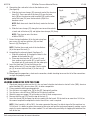
6. Connecting the sand outlet valve to the deadman valve
(See figure 6).
a. Slide the two hose clamps (23) over each end of the abrasive
hose (24). Press one end of the hose (24) over the hose
barb (49) on the abrasive outlet manifold (22) and the other
end of the hose (24) over the hose barb (49) of the
deadman valve.
NOTE: Both hose ends should be firmly seated on the hose
barbs.
b. Slide the hose clamps (23) along the hose to each hose barb
at each end of the hose (24) and tighten hose clamps (23) firmly.
NOTE: They have to resist the force
of 65 to 125 PSI.
7. Fasten the two handlebars (6) to the tank using four
pan screws (8) and four washers (50) and four
hex nuts (9) (See figure 7).
NOTE: Position the curved ends of the handle bars
(6) at the top of the tank (1).
8. Assembling the axle and wheels (See figure 7).
a. Slide the wheel axle (5) through the holes in the
bottom of the handle bars (5).
b. Place one wheel washer (51), wheel (2), and
then another wheel washer (51) at each end of
the wheel axle (5) and secure with the cotter pins (3).
9. Insert the front foot (4) into the fitting on the
bottom of the tank (1) near the edge. Use the cotter
pin (3) to secure the front foot (4) to the tank (1)
(See figure 7).
10. Before beginning operations, check each connection, double checking to ensure that all of the connections
are tight and properly seated.
OPERATION
LOADING ABRASIVES INTO THE TANK
1. Check your abrasive to be sure that it is dry and won’t clog the steel abrasive shut-off valve (18B), abrasive
outlet manifold (22), abrasive hose (24), or other components.
2. Put on protective clothing and equipment.
3. Turn the brass air supply valve (18) to the OFF (horizontal) position.
4. Turn the brass shut-off valve (18B) to the ON (vertical) position.
5. Watch the pressure gauge (15) and make sure that it reads zero pressure.
6. Remove the filler cap (12) from the top of the tank (1).
7. Insert the funnel (29) and pour the abrasive media into the funnel. Fill the tank to no more than 3/4 full, or
the amount required to complete the task at hand if less sand is required.
NOTE: If the humidity is 90 to 100%, the water separator filter won’t be able to trap all of the moisture in a
3/4 full tank. It is better to reduce the amount of abrasive and load the tank more frequently making sure to
empty the water separator filter when needed. This will reduce the possibility of clogging the bottom of the
tank or the line.
Fig. 6
Fig. 7

8 For technical questions call 1-800-665-8685
V 3.05 847411620 Gallon Pressure Abrasive Blaster
8. With the correct amount of abrasive in the tank, replace the filler cap (12).
9. Close the steel abrasive shut-off valve (18B) and open the air supply valve (18).
10. Check for air leaks at the filler cap (12) as you begin to pressurize the tank from the compressor.
WARNING! Watch the pressure gauge! Do allow the pressure in the tank to exceed 125 PSI.
OPERATION
1. Set the compressor’s regulator to 60 to 125 PSI. Do not set the compressor’s outlet regulator over
125 PSI.
NOTE: It is good practice to keep the air compressor in a different room than the room that you will be
performing the abrasive blasting process. The fine dust created during the blasting process can damage
the air compressor. Use a longer air hose in order to reach the abrasive blaster.
2. Connect the air supply to the inlet connector (19).
CAUTION! If any leaks are detected, disconnect the air hose and make any repairs before use.
3. Open the brass air supply valve (18) to pressurize the tank.
NOTE: The brass shut-off valve (18A) and the steel abrasive shut-off valve (18B) should be in the closed
position in order to build pressure in the tank.
WARNING! Watch the pressure gauge! Do allow the pressure in the tank to exceed 125 PSI.
4. Open the brass shut-off valve (18A) to allow air to flow through the air hose (21).
5. Open the steel abrasive shut-off valve (18B) to allow the abrasive to be moved from tank (1). This will
allow the abrasive to mix with the air from the air hose (21) and flow into the abrasive hose (24).
6. Squeeze the On/Off control lever (42) on the deadman valve to begin the abrasive blasting process.
7. When you have finished the abrasive blasting process, release the On/Off control valve (42) and close the
steel abrasive shut-off valve (18B) to stop the flow of abrasives.
8. Close the brass air supply valve (18) to stop the tank from further pressurizing and turn off
your air compressor.
9. Squeeze the On/Off control lever (42) on the deadman valve to relieve the pressure in the tank (1) and the
air line. When the pressure gauge (15) reads 0, the tank has been depressurized.
10. Close the brass shut-off valve (18A) and the brass air supply valve (18) when the tank has been
depressurized and the abrasive blasting process is complete.
OPERATING TIPS
1. The effectiveness of the blaster is increased by holding the nozzle as close to the area being
cleaned as possible.
2. Move the blaster in steady, even strokes over the area to keep the abrasive blasting surface even.
3. When the abrasive blasting process is complete, clean the blasted surface with compressed air or a soft
brush to remove any residual abrasive.
4. Refinish promptly after the blasting process is complete. Newly abrasive blasted surfaces are more
susceptible to corrosion.
TO EMPTY THE ABRASIVE TANK
1. Release the On/Off control valve on the deadman valve (42).
2. Close the steel abrasive shut-off valve (18B).
3. Close the brass air supply valve (18).
NOTE: Turn off the air compressor (if necessary).

Visit www.princessauto.com for more information 9
8474116 V 3.0520 Gallon Pressure Abrasive Blaster
4. Squeeze the On/Off control valve of the deadman valve to relieve pressure in the tank (1).
NOTE: The tank (1) is depressurized when the pressure gauge (15) reads 0.
5. Remove the tank filler cap (12) and empty the abrasive media into a suitable container to
collect the abrasive.
CAUTION! Take care when emptying the tank of abrasives not to damage the pressure gauge or water
separator filter.
NOTE: To prevent abrasive from being blown out of the container, cover part of the container with a board or cloth
to limit the amount of dust scattered.
CAUTION! Wear protective head gear such as goggles and a face protector as well as breathing protection to
avoid breathing in the dust created when emptying the abrasive tank.
MAINTENANCE
NOTE: Disconnect the air source and discharge any residual air pressure in the air line before performing
any maintenance.
1. The ceramic nozzle (37) will wear away over time, causing the internal diameter to widen and disperse the
media over a larger area, reducing the tool’s efficiency. The compressor will also need to work harder to
maintain the pressure. Check the ceramic nozzle at regular intervals and replace as appropriate.
2. Always check for cracks and leaks in the deadman valve, hose, and tank. These problems must be fixed
immediately due to the dangers involved with air under pressure.
3. Check for damaged parts. Before using any tool, any part that appears to be damaged should be carefully
checked to determine that it would operate properly and perform its intended functions. Check for
alignment and binding of moving parts, for broken parts or mounting fixtures, or for any other condition
that may affect proper operation.
NOTE: Internal components of the unit will wear out after repeated exposure to the blasting process. When
the unit’s performance declines, have the unit serviced by a qualified technician.
4. Use only identical replacement parts or accessories intended for use with this tool when servicing. Replace
damaged parts immediately.
5. Keep the tool clean. Wipe the tool with a clean cloth and periodically blow out all areas with compressed
air. If compressed air is not available, use a brush to remove dust from areas. Do not use harsh chemicals
or solvents to clean the tool. These chemicals could seriously damage the housing.
6. The tank filler cap (12) is removable, make sure to clean and remove abrasives from the O-ring rubber
seal (11).
CAUTION! Make sure that the tank has been depressurized before attempting to remove the tank
filler cap (12).
7. After each use of the unit, perform the routine maintenance to your air compressor according to the
compressor manufacturer’s instruction manual.
8. If repairs are required, bring your tool to Princess Auto Ltd.
PLUGGED CONDITIONS
All blasting systems are prone to plugging or wear because of the abrasive material used. The blast nozzle may
become plugged from moist media. Try dislodging the media with a drill bit held in your hand. You will need to
discard the moist media.
The abrasive media contents of the tank (1) may be stirred to loosen the media as well.

10 For technical questions call 1-800-665-8685
V 3.05 847411620 Gallon Pressure Abrasive Blaster
CAUTION! Make sure that the tank has been depressurized before attempting to remove the tank filler
cap (12).
WEAR CONDITIONS
This is usually noted when an excessive amount of dust appears while blasting. Dust will occur if:
1. The abrasive blasting media is worn out if it has lost its granular or spherical appearance or has a lot of
debris mixed in from the parts being blasted. Replace the abrasive blasting media. This is usually noticed
when the abrasive media that exits the nozzle resembles more of a cloud than a stream.
2. The deadman valve parts may wear out. This is usually evident when the blast pattern is too wide and
ineffective; simply replace the nozzle or orifice.
LUBRICATION
Do not use lubricants or air tool oil on the unit. The oil will contaminate the abrasive media, clogging the tool and
reducing the effectiveness of the abrasive.
STORAGE
With a dry, clean cloth or brush, remove any contaminants from the unit and the deadman valve before placing the
unit in storage.
DISPOSING OF THE TOOL
1. If your tool has become damaged beyond repair, do not throw it out. Take it to the appropriate
recycling facility.
2. Abrasive can be re-used until it eventually breaks down or becomes dusty. Dispose of waste abrasives in
accordance with local authority regulations.
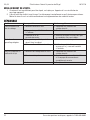
TROUBLE SHOOTING
Problem Possible Cause(s) Suggested Solution(s)
Excessive dust
while blasting.
1. Abrasive media may be worn. 1. Replace the abrasive media.
2. Too much abrasive media in
the hopper.
2. Remove excess abrasive media.
3. Loose air line or fitting connection. 3. Tighten the fitting and make sure the air
lines are secure.
Uneven blasting action. 1. Too much abrasive media in
the hopper.
1. Remove excess abrasive.
2. Moisture is present while blasting. 2. Check the air line to make sure that there
is no moisture in it.
Inadequate speed or
inefficiency of blast.
1. Abrasive media may be worn. 1. Replace the abrasive media.
2. Pressure is too low. 2. Increase the inlet pressure.
WARNING! Do not exceed the maximum
pressure of 125 PSI.
3. Worn nozzle. 3. Replace the nozzle.

Visit www.princessauto.com for more information 11
8474116 V 3.0520 Gallon Pressure Abrasive Blaster
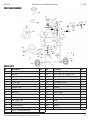
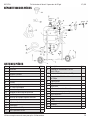
PARTS BREAKDOWN
PARTS LIST
No. Description Qty.
1 Tank 1
2 Wheels 2
3 Cotter Pins 3
4 Front Foot 1
5 Wheel Axle 1
6 Handle Bars 2
7 Handle Grips 2
8 Pan Screws 4
9 Hex Nuts 4
10 Pressure Relief Valve 1
11 O-Ring 1
12 Tank Filler Cap 1
13 Joint Pipe 1
14 Intake Manifold 1
15 Pressure Gauge 1
16 3/8 in. Threaded Bushing 5
No. Description Qty.
17 Water Separator Filter 1
18 3/8 in. Brass Air Supply Valve 1
18A 3/8 in. Brass Shut-Off Valve 1
18B 3/8 in. Steel Abrasive Shut-Off Valve 1
19 Threaded Bushing 1
20 Threaded Bushing 1
21 Air Hose 1
22 Abrasive Outlet Manifold 1
23 Hose Clamps 2
24 Abrasive Hose 1
29 Funnel 1
30 Hood 1
30A Lens For Hood 1
50 Washer 4
51 Wheel Washer 4

12 For technical questions call 1-800-665-8685
V 3.05 847411620 Gallon Pressure Abrasive Blaster
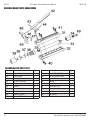
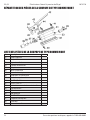
DEADMAN VALVE PARTS BREAKDOWN
DEADMAN VALVE PARTS LIST
No. Description Qty.
31 Upper Body 1
32 Lower Body 1
33 Metal Pipe 1
34 Intake Connector 1
35 Adaptor 1
36 Gasket 1
37 Ceramic Nozzle 4
38 Rubber Adaptor 4
39 Nozzle Cap Nut 1
40 Screw ST 4.2 x 16 4
No. Description Qty.
41 Screw ST 4.2 x 12 2
42 On/Off Control Lever 1
43 Spring Pin 1
44 Spring 1
45 Pivot Block 1
46 Screw M3 x 25 1
47 Hard Alloy Pad 1
48 Nut M3 1
49 Hose Barb 1
Page is loading ...
Page is loading ...
Page is loading ...
Page is loading ...
Page is loading ...
Page is loading ...
Page is loading ...
Page is loading ...
Page is loading ...
Page is loading ...
Page is loading ...
Page is loading ...
Page is loading ...
Page is loading ...
Page is loading ...
Page is loading ...
-
 1
1
-
 2
2
-
 3
3
-
 4
4
-
 5
5
-
 6
6
-
 7
7
-
 8
8
-
 9
9
-
 10
10
-
 11
11
-
 12
12
-
 13
13
-
 14
14
-
 15
15
-
 16
16
-
 17
17
-
 18
18
-
 19
19
-
 20
20
-
 21
21
-
 22
22
-
 23
23
-
 24
24
-
 25
25
-
 26
26
-
 27
27
-
 28
28


Ask a question and I''ll find the answer in the document
Finding information in a document is now easier with AI
in other languages
- français: Power Fist 8474116 Manuel utilisateur
Related papers
-
Power Fist 8549115 Owner's manual
-
-
-
-
-
-
-
-
-
Other documents
-
 Allsource 4100110 User manual
-
Pro Series 551730 User manual
-
 Allsource 41002 User manual
-
 Allsource Import Pressure Blaster 20 Gal 41003 User manual
-
Kobalt SGY-AIR230 User guide
-
Black Bull SB10G User manual
-
Powerfist 8046492 Owner's manual
-
-
Black Bull 800135 User guide
-


