Page is loading ...

(1)(1)
(1)(1)
(1)
MULTI LANGUAGE INSTRUCTIONS:
English...............................................................................................................Page 2
Deutsch.............................................................................................................Page 7
Español............................................................................................................Page 10
Francais..........................................................................................................Page 13
OPERATIONS MANUAL
BEDIENUNGSHANDBUCH
MANUAL DEL OPERADOR
MANUEL D’INSTRUCTIONS
UZ-II28 M, H & L
UZ-9I28 M, H & L
PROFESSIONAL DIVERSITY MICROPHONES
PROFESSIONELLE DIVERSITY-MIKROFONSYSTEME
MICRÓFONOS PROFESIONALES DE LA DIVERSIDAD
MICROPHONES PROFESSIONNELS DE DIVERSITÉ

(2)(2)
(2)(2)
(2)
PLEASE READ BEFORE USING APPLIANCE,
IMPORTANT WARNING & SAFETY INSTRUCTIONS!
CAUTION
RISK OF ELECTRICAL SHOCK
DO NOT OPEN!
READ INSTRUCTIONS: All the safety and operating instructions should be read
before the product is operated.
RETAIN INSTRUCTIONS: The safety and operating instructions should be retained for
future reference.
HEED WARNINGS: All warnings on the product and in the operating instructions
should be adhered to.
FOLLOW INSTRUCTIONS: All operating and use instructions should be followed.
CLEANING: The product should be cleaned only with a polishing cloth or a soft dry
cloth. Never clean with furniture wax, benzine, insecticides or other volatile liquids
since they may corrode the cabinet.
ATTACHMENTS: Do not use attachments not recommended by the product
manufacturer as they may cause hazards.
WATER AND MOISTURE: Do not use this product near water, for example, near a
bathtub, wash bowl, kitchen sink, or laundry tub; in a wet basement; or near a
swimming pool; and the like.
ACCESSORIES: Do not place this product on an unstable cart, stand, tripod, bracket,
or table. The product may fall, causing serious injury to a child or adult, and serious
damage to the product. Use only with a cart, stand, tripod, bracket, or table
recommended by the manufacturer, or sold with the product. Any mounting of the
product should follow the manufacturer’s instructions, and should use a mounting
accessory recommended by the manufacturer.
CART: A product and cart combination should be moved with care. Quick stops, excessive
force, and uneven surfaces may cause the product and cart combination to overturn.
See Figure A.
VENTILATION: Slots and openings in the cabinet are provided for ventilation and to
ensure reliable operation of the product and to protect it from overheating, and
these openings must not be blocked or covered. The openings should never be
blocked by placing the product on a bed, sofa, rug, or other similar surface. This product
should not be placed in a built-in installation such as a bookcase or rack unless proper
ventilation is provided or the manufacturer’s instructions have been adhered to.
POWER SOURCES: This product should be operated only from the type of power
source indicated on the marking label. If you are not sure of the type of power
supply to your home, consult your product dealer or local power company.
LOCATION: The appliance should be installed in a stable location.
NON-USE PERIODS: The power cord of the appliance should be unplugged from the
outlet when left unused for a long period of time.
GROUNDING OR POLARIZATION:
• If this product is equipped with a polarized alternating current line plug (a plug
having one blade wider than the other), it will fit into the outlet only one way. This is
a safety feature. If you are unable to insert the plug fully into the outlet, try reversing
the plug. If the plug should still fail to fit, contact your electrician to replace your
obsolete outlet. Do not defeat the safety purpose of the polarized plug.
• If this product is equipped with a three-wire grounding type plug, a plug having a
third (grounding) pin, it will only fit into a grounding type power outlet. This is a
safety feature. If you are unable to insert the plug into the outlet, contact your
electrician to replace your obsolete outlet. Do not defeat the safety purpose of the
grounding type plug.
POWER-CORD PROTECTION: Power-supply cords should be routed so that they are
not likely to be walked on or pinched by items placed upon or against them, paying
particular attention to cords at plugs, convenience receptacles, and the point where
they exit from the product.
OUTDOOR ANTENNA GROUNDING: If an outside antenna or cable system is
connected to the product, be sure the antenna or cable system is grounded so as
to provide some protection against voltage surges and built-up static charges.
Article 810 of the National Electrical Code, ANSI/NFPA 70, provides information
with regard to proper grounding of the mast and supporting structure, grounding of
the lead-in wire to an antenna discharge unit, size of grounding conductors, location
of antenna-discharge unit, connection to grounding electrodes, and requirements for
the grounding electrode. See Figure B.
LIGHTNING: For added protection for this product during a lightning storm, or when it
is left unattended and unused for long periods of time, unplug it from the wall outlet
and disconnect the antenna or cable system. This will prevent damage to the
product due to lightning and power-line surges.
POWER LINES: An outside antenna system should not be located in the vicinity of
overhead power lines or other electric light or power circuits, or where it can fall into
such power lines or circuits. When installing an outside antenna system, extreme
care should be taken to keep from touching such power lines or circuits as contact
with them might be fatal.
OVERLOADING: Do not overload wall outlets, extension cords, or integral
convenience receptacles as this can result in a risk of fire or electric shock.
OBJECT AND LIQUID ENTRY: Never push objects of any kind into this product
through openings as they may touch dangerous voltage points or short-out parts
that could result in a fire or electric shock. Never spill liquid of any kind on the product.
SERVICING: Do not attempt to service this product yourself as opening or removing
covers may expose you to dangerous voltage or other hazards. Refer all servicing
to qualified service personnel.
DAMAGE REQUIRING SERVICE: Unplug this product from the wall outlet and refer
servicing to qualified service personnel under the following conditions:
• When the power-supply cord or plug is damaged.
• If liquid has been spilled, or objects have fallen into the product.
• If the product has been exposed to rain or water.
• If the product does not operate normally by following the operating instructions. Adjust only
those controls that are covered by the operating instructions as an improper adjustment of
other controls may result in damage and will often require extensive work by a qualified
technician to restore the product to its normal operation.
• If the product has been dropped or damaged in any way.
• When the product exhibits a distinct change in performance, this indicates a need for service.
REPLACEMENT PARTS: When replacement parts are required, be sure the service
technician has used replacement parts specified by the manufacturer or have the
same characteristics as the original part. Unauthorized substitutions may result in
fire, electric shock, or other hazards.
SAFETY CHECK: Upon completion of any service or repairs to this product, ask the
service technician to perform safety checks to determine that the product is in
proper operating condition.
WALL OR CEILING MOUNTING: The product should not be mounted to a wall or ceiling.
HEAT: The product should be situated away from heat sources such as radiators,
heat registers, stoves, or other products (including amplifiers) that produce heat.
CAUTION: THIS PRODUCT SATISFIES FCC REGULATIONS WHEN SHIELDED CABLES AND
CONNECTORS ARE USED TO CONNECT THE UNIT TO OTHER EQUIPMENT. TO PREVENT
ELECTROMAGNETIC INTERFERENCE WITH ELECTRIC APPLIANCES SUCH AS RADIOS AND
TELEVISIONS, USE SHIELDED CABLES AND CONNECTORS FOR CONNECTIONS.
THE EXCLAMATION POINT WITHIN AN EQUILATERAL TRIANGLE IS INTENDED TO ALERT
THE USER TO THE PRESENCE OF IMPORTANT OPERATING AND MAINTENANCE
(SERVICING) INSTRUCTIONS IN THE LITERATURE ACCOMPANYING THE APPLIANCE.
THE LIGHTNING FLASH WITH ARROWHEAD SYMBOL, WITHIN AN EQUILATERAL
TRIANGLE, IS INTENDED TO ALERT THE USER TO THE PRESENCE OF UNINSULATED
“DANGEROUS VOLTAGE” WITHIN THE PRODUCT’S ENCLOSURE THAT MAY BE OF
SUFFICIENT MAGNITUDE TO CONSTITUTE A RISK OF ELECTRIC SHOCK TO PERSONS.

(3)(3)
(3)(3)
(3)
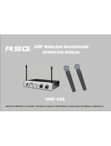
UZ-ii28/UZ-9128UZ-ii28/UZ-9128
UZ-ii28/UZ-9128UZ-ii28/UZ-9128
UZ-ii28/UZ-9128
ZM-128 HANDHELD MICROPHONE ZB-128 BODYPACK
UZ-1128 RECEIVER UZ-9128 RECEIVER

(4)(4)
(4)(4)
(4)
• Before setting up, make sure that the transmitter and receiver are tuned
to the same frequency.
• Do not use two transmitters in the same frequency. Use good quality
batteries to avoid the damage resulting from a defective leaking battery.
• Turn the volume control on the receiver to adjust receiver output level to
match input level requirements of an audio mixer or amplifier.
• While checking sound, move the transmitter around the area where you
use the system to look for dead spots. If you find any dead spot, change
the receiver position. If it does not work, avoid such places.
• To avoid interference, do not put the receiver too near metal object and
avoid obstructions between transmitter and receiver.
• Avoid the interference from TV, radio, other wireless appliances and etc.
FUNCTION DESCRIPTIONS:
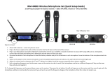
UZ-1128 & UZ-9128 RECEIVERS:
(1) HEADPHONE MONITOR VOLUME CONTROL: Rotate this knob to
control headphone volume level.
(2)HEADPHONE INPUT CONNECTOR: Plug headphone into this 1/4” jack
connector to monitor receiver audio.
NOTE: NUMBERS (3)-(11) APPLY TO BOTH UZ-1128 & UZ-9128 RECIEVERS.
(3)POWER: Pushes the receiver on and off.
(4)CHANNEL + BUTTON: Press this button to change channel forward.
(5)CHANNEL - BUTTON: Press this button to change channel backward.
(6)PROGRAMMABLE DISPLAY: Displays channel number, frequency and
volume level.
(7)RF LEVEL INDICATORS: Five LEDs per RF antenna channel glow to
indicate RF signal strength. The more LEDs that glow, the stronger the
received signal. If none of these LEDs glow, no signal is being received.
(8) AF LEVEL INDICATORS: Five LEDs glow to indicate audio signal
strength. Green indicates normal operation. RED indicates approaching
overload condition.
(9)VOLUME + BUTTON: Press this button to increase the receiver output
level to match the input sensitivity of an audio mixer or an amplifier.
(10) VOLUME - BUTTON: Press this button to decrease the receiver output
level to match the input sensitivity of an audio mixer or an amplifier.
(11) DC OUT: Connect the supplied cable to the receiver and the microphone,
and it takes around 10 hours to charge.
(12) ANTENNA INPUT CONNECTOR: TNC-type connectors provide
connection to the supplied antennas or to coaxial cable used with an
antenna divider, antenna boosters or remote antennas.
(13) ANTENNA: Fixed-length UHF antenna permanently mounted on rear panel.
NOTE: NUMBERS (14)-(17) APPLY TO BOTH UZ-1128 & UZ-9128 RECIEVERS.
(14) BALANCED OUTPUT: 3-pin XLR connector provides balanced low-
impedance output
(15) UNBALANCED OUTPUT: 1/4” phone jack provides unbalanced low-
impedance output
(16) SQUELCH: The squelch adjusts the output level to suppress the noise.
The higher squelch control, the lower the sensitivity of the receiver and
decrease the service area of the system. Set the squelch to minimum
before turning the receiver on.
(17) DC IN: Input connector for the supplied AC adapter.
To combine two receivers in a 19" standard rack by using 2 short L type plastic
racks (L2) and 2 metal connecting plates (C1).
INTRODUCTION:
Congratulations on your purchase of a GEMINI wireless system. This
state of the art unit includes all the latest features backed by a three
year limited warranty. Prior to use, we suggest that you carefully read
the instructions.
SYSTEM FEATURES:
• UZ-1128 M includes UZ-1128 diversity receiver & ZM-128 handheld microphone
• UZ-1128 H includes UZ-1128 diversity receiver, HSM-X4 headset mic with mini XLR
& ZB-128 belt pack transmitter with mic/line switch
• UZ-1128 L includes UZ-1128 diversity receiver, LAV-X4 lavalier mic with mini XLR
& ZB-128 belt pack transmitter with mic/line switch
• UZ-9128 M includes UZ-9128 true diversity receiver & ZM-128 handheld microphone
• UZ-9128 H includes UZ-9128 true diversity receiver, HSM-X4 headset mic with mini XLR
& ZB-128 belt pack transmitter with mic/line switch
• UZ-9128 L includes UZ-9128 true diversity receiver, LAV-X4 lavalier mic with mini XLR
& ZB-128 belt pack transmitter with mic/line switch
• Balanced & unbalanced outputs
• 128 band UHF synthesizer controlled frequencies
• Phase locked loop (PLL) circuitry
• Super high sensitivity with extremely low noise transmission & reception
• Stable & quality SMT assembled PCB module
• LCD display screen
• RF & AF LED meters
• Squelch control
• ¼” earphone output for UZ-1128
• ZM-128 has a uni-directional condenser unit microphone
• HSM-X4 has an electret condenser unit microphone
• LAV-X4 has an electret condenser unit microphone
• ZM-128 has a rechargeable input for battery recharging
CAUTIONS:
1. In the UK Some wireless microphone systems require a license. This
depends on the frequency of the system and the country in which it is
to be used. It is the responsibility of the user to establish if a license is
required. As a guide, for the UK and Europe, VHF radio microphones
between 173.800 and 175.000 MHz, or UHF microphones between 863
MHz and 865 MHz do not need a license. This is for microphones work
ing at normal power (10mW ERP hand-held or 50mW ERP if body
worn). All other use on alternative frequencies needs a license. More
information on this can be found at :www.jfmg.co.uk/jfmgecom/
default.aspx If in any doubt, users are advised to investigate the
licensing requirements for their region.
2. All operating instructions should be read before using this equipment.
3. To reduce the risk of electrical shock, do not open the unit. THERE ARE
NO USER REPLACEABLE PARTS INSIDE. Please refer servicing to a
qualified service technician.
4. Do not expose this unit to direct sunlight or to a heat source such as a
radiator or stove.
5. Dust, dirt and debris can interfere with the performance of this unit. Make
an effort to keep the unit away from dusty, dirty environments, and cover
the unit when it is not in use. Dust it regularly with a soft, clean brush.
6. When moving this equipment, it should be placed in its original carton
and packaging. This will reduce the risk of damage during transit.
7. DO NOT EXPOSE THIS UNIT TO RAIN OR MOISTURE.
8. DO NOT USE ANY SPRAY CLEANER OR LUBRICANT ON ANY
CONTROLS OR SWITCHES.
9. REMEMBER, ANY CHANGES MADE TO THE UNIT WITHOUT
AUTHORIZATION FROM GEMINI WILL VOID YOUR WARRANTY.
FCC RULES AND REGULATIONS:
This device complies with part 15 of the FCC rules. Operation is subject
to the following two conditions: (1)This device may not cause harmful
interference and (2) This device must accept any interference received,
including interference that may cause undesired operation
NOTICE: THE CHANGES OR MODIFICATIONS NOT EXPRESSLY APPROVED BY THE PARTY
RESPONSIBLE FOR COMPLIANCE COULD VOID THE USER’S AUTHORITY TO OPERATE
THE EQUIPMENT.
IMPORTANT NOTE, TO COMPLY WITH THE FCC RF EXPOSURE COMPLIANCE REQUIREMENTS, NO
CHANGE TO THE ANTENNA OR THE DEVICE IS PERMITTED. ANY CHANGE TO THE ANTENNA
OR THE DEVICE COULD RESULT IN THE DEVICE EXCEEDING THE RF EXPOSURE
REQUIREMENTS AND VOID USER’S AUTHORITY TO OPERATE THE DEVICE.
UZ-1128 WIRELESS SYSTEM:
The UZ-1128 & UZ-9128 wireless systems are high quality audio products
that provide excellent performance under most operating conditions. The
receivers are used with our 700 selectable channels transmitters. The
receiver operates in UHF band frequency with PLL synthesized control.
Powered by 12V DC. Operating in UHF band frequency with synthesizer
controlled. The wireless microphone system with 700 selectable
frequencies via Phase Locked Loop (PLL) circuitry makes it easy to choose
non-interfered channels. Super high sensitivity, extremely low noise
transmission and reception. Diversity technology ensures the reception
quality.
WIRELESS NOTES:

(5)(5)
(5)(5)
(5)
To mount a receiver in a 19" standard rack by using 2 long L type metal
racks (L1).
CHARGING CONNECTING DIAGRAM:
Connect the supplied DC cable to the receiver and the microphone, and it takes
around 10 hours to charge and the LED of transmitter is flashing all the time.
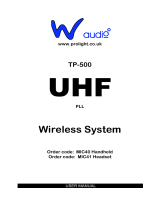
ZM-128 HANDHELD MICROPHONE:
The handheld microphone operates in UHF band frequency with PLL
synthesized control. UHF 700 preprogrammed selectable frequencies to
avoid interference. Uni-directional dynamic or uni-directional electret
condenser cartridges feature different characters for various choices. Use
1.5V x 2 AA size dry or rechargeable batteries for cost saving and
environmental protection.
(1)GRILLE: Protects the microphone capsule and helps reduce breath
sounds and wind noise.
(2) PROGRAMMABLE DISPLAY: Displays channel number and battery power level
(3) ON/OFF SWITCH: Turns transmitter power on and off.
(4) BATTERY COMPARTMENT: Insert 2 x1.5V AA dry or rechargeable batteries
into the compartment and make sure that the polarity of batteries is correct.
(5) CHANNEL + BUTTON: Press this button to change channel forward.
(6) CHANNEL BUTTON: Press this button to change channel backward.
(7) BATTERY COVER: Unscrew to expose battery compartment and
channel buttons.
(8) COLOR CLIP: This color clip helps to identify the frequency for multi-
channel operation.
(9) CHARGING INPUT: The inserted rechargeable batteries are charged by
using the supplied DC-plug cable connection to DC Out on the receiver.
It takes up to 10 hours for charging.
ZB-128 BODYPACK TRANSMITTER:
The bodypack transmitter operates in UHF band frequency with PLL
synthesized control. UHF 700 preprogrammed selectable frequencies to
avoid interference. Various uni-directional electret condenser cartridge
options. Use 1.5V x 2 AA size dry or rechargeable batteries for low
operating cost.
(1)ON/OFF SWITCH: Turns transmitter power on and off.
(2)3-PIN MINI XLR CONNECTOR: The included electret lapel microphone
is inserted into the connector on transmitter.
(3)PROGRAMMABLE DISPLAY: Displays channel number and battery power level
(4)CHANNEL + BUTTON: Press this button to change channel forward.
(5)CHANNEL BUTTON: Press this button to change channel backward.
(6)MIC/LINE SELECTOR: The switch sets the audio input either to
microphone level or line level.
(7)GAIN: The rotary control adjusts the sensitivity of the transmitter’s audio
to the level of the connected lapel microphone or instrument.
(8)BATTERY COMPARTMENT: Insert 2 X 1.5V AA dry or rechargeable batteries
into the compartment and make sure that the polarity of batteries is correct.
(9)MIC UNIT: The uni-directional electret condenser unit features the wide
frequency response for warm, rich bass and clear sound.
(10) TIE CLIP: To clip on the tie or lapel for free-movement.
(11) CABLE: With 3-pin mini XLR connector cable to connect the transmitter.
(12) ANTENNA: Permanently connected, helical antenna.
(13) CHARGING INPUT: The inserted rechargeable batteries are charged by
using the supplied DC-plug cable connection to DC Out on the receiver.
It takes up to 10 hours for charging.
SETTING UP:
Prior to setting up, check that the transmitter and receiver are tuned to
the same frequency. Two or above transmitters operating in the same
frequency can not be used at the same time and area, so please select
the different frequencies which can be used simultaneously at local area.
BASIC CONNECTIONS:
Connect the receiver output to the audio mixer or amplifier input, using a
standard audio cable with 3-pin XLR connectors or 1/4” phone plugs.
Never use the balanced and unbalanced audio outputs at the same time!
This may cause signal loss or increased noise.
AB-8A, the antenna booster is highly recommended for long-distance
purpose, such as in stadium or in auditorium. By means of antenna
holder, the antenna and booster can put wherever you want. It is an ideal
design for multi-channel application. Antenna boosters are applied to the
receivers, which have detachable antennas.
AH-1 Antenna holder makes it easy to fix wherever for connection antenna and
booster. AH-1 can be assembled on the mic stand or on the wall.

(6)(6)
(6)(6)
(6)
CONNECTING THE RECEIVER TO POWER:
Plug the antennas into the TNC socket on the receiver, if the antennas
are detachable. Point the antennas upward. Check that the voltage of
the supplied AC adapter conforms to the voltage available (AC110 or
AC220) in local area. Using the wrong AC adapter may cause irreparable
damage to the unit. Plug the feeder cable of the supplied AC adapter
into DC IN socket on the receiver. Then plug the AC adapter into a
power outlet.
TO A RECEIVER TO AN AUDIO MIXER OR
AN AMPLIFIER:
When using a standard audio cable with 3-pin XLR connectors or 1/8th”
phone plugs to plug into the MIC IN on the audio mixer or on the
amplifier, please push the Volume Button on the receiver to 20 (approx.) ,
the output level for balanced and unbalanced output is around at 77mV.
When using a standard audio cable with 3-pin XLR connectors or 1/8th”
phone plugs to plug into the LINE IN on the audio mixer or on the
amplifier, please push the Volume Button on the receiver to 32, the
output level for unbalanced and balanced output is about at 770mV.
Never use the balanced and unbalanced audio outputs at the same time!
This may cause signal loss or increased noise.
INSERTING BATTERIES INTO THE HANDHELD /
BODYPACK TRANSMITTER:
Open the battery cover and insert batteries into the battery compartment
conforming to the polarity (+)(-) marks. The transmitter can not work with
incorrectly inserted batteries. When push the ON/OFF switch to “ON” to
switch the power on, LCD shows battery power level. If it displays
insufficient power, the inserted rechargeable batteries can be charged
by using the supplied DC 1.5 plug cable directly connection to DC Out
on the receiver and charging input on the transmitter. It should take up to
10 hours for charging. Close the battery cover.
SETTING UP THE HANDHELD MICROPHONE TRANSMITTER:
Switch the receiver power on and check the frequency and volume level.
Switch the transmitter and hi-fi appliance (amplifier, tape deck etc.) power on.
Test the microphone and adjust the levels on your audio mixer or amplifier.
SETTING UP THE BODYPACK TRANSMITTER
A. CONNECTING A MICROPHONE:
Open the battery cover. Push the MIC/LINE switch to “MIC” and use the
supplied screwdriver to adjust the GAIN at appropriate position.
Plug the 3-pin mini XLR connector end of the microphone cable into the
audio input connector on the bodypack transmitter. Switch the transmitter
and hi-fi appliance (amplifier, tape deck etc.) power on. Test the
microphone and adjust the levels on your audio mixer or amplifier.
B. CONNECTING AN INSTRUMENT:
Open the battery cover. Push the MIC/LINE switch to “LINE” and use the
supplied screwdriver to adjust the GAIN at appropriate position.
Plug the 1/4th” phone plug of the optional guitar cable to the output jack
on the instrument and the 3-pin mini XLR into audio input connector on
the bodypack transmitter. Switch the transmitter and hi-fi appliance (amplifier,
tape deck etc.) power on. Play the instrument for testing and adjust
the levels on your audio mixer or amplifier.
TROUBLE-SHOOTING:
NO SOUND:
Check the power supply of the microphone and receiver.
Check that the transmitter and receiver are tuned to the same frequency.
Check whether the hi-fi appliance is switched on and the receiver output
is connected to mixer or amplifier input.
Check whether transmitter is too far away from receiver or SQUELCH
control set too high.
Check whether receiver is located too near metal object or there are
obstructions between transmitter and receiver.
SOUND INTERFERENCE:
Check the antenna location.
When using 2 or above microphone sets simultaneously, make sure
that the chosen frequencies are not interfered.
Check whether the interference comes from other wireless microphones,
TV, radio and etc.
DISTORTION:
Check the volume level of the receiver is set too high or too low.
Check whether the interference comes from other wireless microphones,
TV, radio and etc.
SPECIFICASPECIFICA
SPECIFICASPECIFICA
SPECIFICA
TIONS:TIONS:
TIONS:TIONS:
TIONS:
RECEIVERS:RECEIVERS:
RECEIVERS:RECEIVERS:
RECEIVERS:
UZ-1128:UZ-1128:
UZ-1128:UZ-1128:
UZ-1128:
Frequency range....................................................................................USA-740-770MHz = 700CH
.........................Europe A-France/Spain: 740-770MHz = 700CH B-UK/Germany: 840 - 870MHz = 700CH
Case.....................................................................................................................Half 19" EIA Case
Receiving System...................................................................................................PLL synthesized
Receiving Mode.........................................................................Single Channel, Switching diversity
Frequency Stability............................................................................................................+/- 0.05%
Receiving Sensitivity..........................................................................At 8 dBuV over 80dB S/N ratio
Image & Spurious Rej...............................................................................................80 dB minimum
Selectivity..............................................................................................................................> 50dB
Modulation Mode.........................................................................................................................FM
IF Frequency............................................................................................1st: 56MHz 2nd: 10.7MHz
Dynamic Range......................................................................................................................>96dB
Tone Signal.....................................................................................................................32.768KHz
S/N Response........................................Over 94dB, at 48KHz deviation and 60dBuV antenna input
AF Response................................................................................................50Hz to 15KHz(+/-3dB)
T.H.D. ........................................................................................................................<1%(at 1KHz)
Power Supply................................................................................................................DC 12 ~ 18V
Audio Output.....................................................................................Balanced & unbalanced output
Current Consumption..............................................................................................260mA +/- 10mA
Dimension(mm)WxHxD..............................................................................................210 x 44 x 165
UZ-9128:UZ-9128:
UZ-9128:UZ-9128:
UZ-9128:
Frequency range.................................................................................USA: 740 - 770MHz = 700CH
......................Europe A-France/Spain: 740 - 770MHz = 700CH B-UK/Germany: 840 - 870MHz = 700CH
Case...................................................................................................................19" EIA Metal Case
Receiving System...................................................................................................PLL synthesized
Receiving Mode.................................................................................Single Channel, True-diversity
Frequency Stability............................................................................................................+/- 0.05%
Receiving Sensitivity..........................................................................At 8 dBuV over 80dB S/N ratio
Image & Spurious Rej...............................................................................................80 dB minimum
Selectivity..............................................................................................................................> 50dB
Modulation Mode.........................................................................................................................FM
IF Frequency............................................................................................1st: 56MHz 2nd: 10.7MHz
Dynamic Range......................................................................................................................>96dB
Tone Signal.....................................................................................................................32.768KHz
S/N Response........................................Over 94dB, at 48KHz deviation and 60dBuV antenna input
AF Response................................................................................................50Hz to 15KHz(+/-3dB)
T.H.D..........................................................................................................................<1%(at 1KHz)
Power Supply................................................................................................................DC 12 ~ 18V
Audio Output.....................................................................................Balanced & unbalanced output
Current Consumption..............................................................................................300mA +/- 10mA
Dimension(mm)WxHxD..............................................................................................420 x 45 x 180
ZM-128:ZM-128:
ZM-128:ZM-128:
ZM-128:
Mic Type.........................................................................................................Handheld microphone
Frequency range.................................................................................USA: 740 - 770MHz = 700CH
.....................Europe: A-France/Spain: 740 - 770MHz = 700CH B-UK/Germany: 840 - 870MHz = 700CH
RF Power Output..........................................................................................................10mW(max.)
Oscillation Mode.....................................................................................................PLL synthesized
Frequency Stability..........................................................................................................+/- 0.005%
Maximum Deviation.....................................................................+/-48KHz with limiting compressor
Spurious Emission............................................................................>60 dB below carrier frequency
T.H.D..........................................................................................................................<1%(at 1KHz)
Chargeable Battery.......................................................................DC 3V(1.5v x 2 AA size batteries)
Tone Key.........................................................................................................................32.768KHz
Mic Unit.................................................................................................Uni-directional dynamic unit
LED Indicator...................................................................................Power ON-OFF and low battery
Current Consumption.......................................................................................................65 +/- 5mA
Dimension(mm)WxHxD.......................................................................................................266 x 55
ZB-128ZB-128
ZB-128ZB-128
ZB-128
Mic Type.....................................................................................Bodypack transmitter
Frequency range....................................................................USA: 740 – 770MHz = 700CH
.................Europe:A-France/Spain: 740 - 770MHz = 700CH B-UK/Germany: 840 - 870MHz = 700CH
RF Power Output........................................................................................10mW(max.)
Oscillation Mode....................................................................................PLL synthesized
Frequency Stability.............................................................................................+/- 0.005%
Maximum Deviation.................................................................+/-48KHz with limiting compressor
Spurious Emission...............................................................>60 dB below carrier frequency
T.H.D......................................................................................................................<1%(at 1KHz)
Chargeable Battery.........................................................DC 3V(1.5V x 2 AA size batteries)
Tone Key.......................................................................................................32.768KHz
Mic Unit...........................................................................Uni-directional condenser unit
LED Indicator..........................................................................Power ON-OFF and low battery
Current Consumption.....................................................................................65 +/- 5mA
Dimension(mm)WxHxD.............................................................................65 x 100 x 27
DESIGN & SPECIFICADESIGN & SPECIFICA
DESIGN & SPECIFICADESIGN & SPECIFICA
DESIGN & SPECIFICA
TIONS SUBJECT TTIONS SUBJECT T
TIONS SUBJECT TTIONS SUBJECT T
TIONS SUBJECT T
O CHANGE WITHOUT NOO CHANGE WITHOUT NO
O CHANGE WITHOUT NOO CHANGE WITHOUT NO
O CHANGE WITHOUT NO
TICE.TICE.
TICE.TICE.
TICE.

(7)(7)
(7)(7)
(7)
BEDIENUNGSHANDBUCH:
Herzlichen Glückwunsch zum Erwerb einer drahtlosen UHF-Anlage von
GEMINI. Diese, nach dem neuesten Stand der Technik hergestellte
Anlage, ist mit einer limitierten Garantie von drei Jahren versehen. Bitte
vor Gebrauch der Anlage unbedingt diese Anweisungen beachten.
SYSTEM AUSSTATTUNG:
• UZ-1128 M besteht aus dem UZ-1128 Diversityempfänger und dem Handsender ZM-128
• UZ-1128 H besteht aus dem UZ-1128 Diversityempfänger, dem Taschensender ZB-128 mit
Mic-/Lineschalter und dem HSM-X4 Headset mit Mini-XLR-Stecker
• UZ-1128 L besteht aus dem UZ-1128 Diversityempfänger, dem Taschensender ZB-128 mit
Mic-/Lineschalter und dem LAV-X4 Lavaliermikrofon mit Mini-XLR-Stecker
• UZ-9128 M besteht aus dem UZ-9128 True Diversity Empfänger und dem Handsender ZM-128
• ZM-128 hat ein Electretkondensatormikrofon mit Nierencharakteristik und nachladbarem Eingang
• UZ-9128 H besteht aus dem UZ-9128 True Diversity Empfänger, dem Taschensender ZB-128
• mit Mic-/Lineschalter und dem HSM-X4 Headset mit Mini-XLR-Stecker
• UZ-9128 L besteht aus dem UZ-9128 True Diversity Empfänger, dem Taschensender ZB-128
mit Mic-/Lineschalter und dem LAV-Z4 Lavaliermikrofon mit Mini-XLR-Stecker
• Symmetrische und unsymmetrische Ausgänge
• 128-Band UHF-Frequenzen, Synthesizer gesteuert
• PLL-Schaltkreis
• Hohe Übertragungsempfindlichkeit bei niedrigstem Rauschen
• Stabile und hochqualitative SMT-Platinen
• LCD-Display
• LED-Ketten für RF & AF
• Regelbare Rauschsperre (Squelch)
• UZ-9128 Kopfhörerausgang mit 6,3mm Klinkenbuchse
• ZB-128 hat eine Mini-XLR-Buchse und nachladbarem Eingang
• HSM-X4 ist mit einem Electretkondensatormikrofon mit Nierencharakteristik bestückt
• ZM-128 hat ein Electretkondensatormikrofon mit Nierencharakteristik und nachladbarem Eingang
• LAV-X4 ist mit einem Electretkondensatormikrofon mit Nierencharakteristik bestückt•128-Band
WICHTIGE HINWEISE:
1. Vor Inbetriebnahme der Funkanlage ausserhalb des Frequenzbereiches
863-865 Mhz, wenden Sie sich bitte unbedingt an die zuständige lokale
Regulierungsbehörde oder besuchen Sie: http://www.regtp.de/schriften
02222/01/index.html, um die anmelde- und gebührenpflichtigen
Frequenzen zu erfragen.
2. Vor Gebrauch der UHF-Anlage bitte alle Anweisungen lessen.
3. Um einen Stromschlag zu vermeiden, das Gerät nicht öffnen. Es
beinhaltet keine vom Anwender auszutauschenden Teile. Bitte setzen Sie
sich im Servicefall mit Ihrem Händler in Verbindung.
4. Setzen Sie die Anlage keiner großen Wärme (Heizung, Ofen) und keiner
direkten Sonnen-einstrahlung aus.
5. Schmutz und Staub können den Betrieb der Anlage stören. Vermeiden
Sie daher den Betrieb in staubiger Umgebung und decken Sie die Anlage
bei nicht Betrieb ab. Reinigen nur mit einem trocken weichen Tuch.
6. Zum Transport und Schutz gegen Schäden eignet sich am Besten die
Originalverpackung.
7. Setzen Sie die Anlage keiner starken Feuchtigkeit oder Regen aus.
8. Nehmen Sie niemals Kontaktsprays oder Sprühöl für die Schalter und
Regler.
9. Bitte denken Sie daran das bei jedem technischen Eingriff innerhalb der
Garantiezeit der Garantieanspruch erlischt.
FCC UND RBT BESTIMMUNGEN:
Diese Anlage entspricht den Bestimmungen der RBT für drahtlose UHF-
Anlagen und den FCC Bestimmungen nach Teil 15. Der Betrieb muß die
folgenden beiden Bedingungen erfüllen: (1)Diese Anlage darf im Betrieb
keine Störungen (Interferenzen) verursachen und (2) muß beim Empfang
Störungen (Interferenzen) akzeptieren auch solche, die einen normalen
Betrieb ausschließen.
ACHTUNG: ÄNDERUNGEN UND MODIFIKATIONEN DIE VOM HERSTELLER NICHT ERPROBT
UND ZUGELASSEN SIND, FÜHREN ZUM ERLÖSCHEN DER BETRIEBSERLAUBNIS DER ANLAGE.
WICHTIG: UM DEN BESTIMMUNGEN ZUR ABSTRAHLUNG VON UHF-FREQUENZEN ZU
ENTSPRECHEN, DÜRFEN AN DEN GERÄTEN ODER DEN ANTENNEN KEINE ÄNDERUNGEN
VORGENOMMEN WERDEN. JEDE ÄNDERUNG KANN DIE UHF-STRAHLUNG VERSTÄRKEN
UND FÜHRT ZUM ERLÖSCHEN DER BETRIEBSERLAUBNIS.
UZ-1128 & UZ-9128 UHF-SYSTEM:
Die UZ-1128 und UZ-9128 sind qualitativ hochwertige Audiosysteme, die
unter fast allen Bedingungen hervorragend funktionieren. Die Empfänger
werden mirt unseren Sendern mit 700 wählbaren Kanälen betrieben. Der
Empfänger arbeitet im UHF-Band mit Synthesizer- gesteuertem PLL-
Schaltkreis. Die Betriebsspannung beträgt 12 V= . Durch die 700 PLL-
gesteuerten Kanäle ist ein einfaches Einstellen störungsfreier Kanäle
möglich. Die Diversitytechnologie ermöglicht einen sehr rausch- und
störungsarmen Sende- und Empfangsbetrieb.
HINWEISE ZUM DRAHTLOSBETRIEB:
• Vor dem Betrieb an einer Audioanlage, Sender und Empfänger auf die
gleiche Frequenz ein- stellen.
• Betreiben Sie nie zwei Sender mit gleicher Frequenz. Nehmen Sie zum
Betrieb nur qualitativ hochwertige Batterien um Schäden durch
• Batterielecks zu vermeiden.
• Passen Sie den Ausgangspegel des Empfängers mit dem
• Lautstärkeregler, an die Eingangs-empfindlichkeit Ihres Mixers oder
Verstärkers an.
• Beim Soundcheck gehen Sie mit dem Sender den gesamten
Anwendungsbereich des Systems ab um eventuelle Empfangslöcher
aufzuspüren. Wenn Sie solche Löcher finden sollten, verändern sie die
Position des Empfängers und testen sie erneut.
• Um Störungen(Interferenzen) zu vermeiden, stellen Sie den Empfänger
nicht zu nahe an Metallgegenstände und arbeiten Sie mit dem Sender
nicht zu dicht am Empfänger.
• Vermeiden Sie Störungen durch Radios, Fernseher oder andere
Drahtlosanlagen.
FUNKTIONSBESCHREIBUNG:
UZ-1128 UND UZ-9128 EMPFÄNGER:
(1) HEADPHONE MONITOR VOLUME CONTROL: Derehen Sie diesen
Knopf um die Kopfhörerlaut-stärke zu regeln.
(2) HEADPHONE INPUT CONNECTOR: Schliessen Sie hier Ihren
Kopfhörer an, um das Audiosignal des Empfängers zu hören.
BEACHTEN SIE: DIE NUMMERN (3) BIS (11) GELTEN FÜR BEIDE EMPFÄNGER UZ-1128 & UZ-9128
(3) POWER: Schaltet den Empfänger Ein und Aus Channel+ Knopf:
Drücken Sie diesen Knopf um den Kanal vorwärts zu ändern. Channel-
(4) CHANNEL + KNOPF: Drücken Sie diesen Knopf um den Kanal vorwärts
zu ändern.
(5)CHANNEL - KNOPF: Drücken Sie diesen Knopf um den Kanal rückwärts
zu ändern.
(6) PROGRAMMABLE DISPLAY: Zeigt Kanalnummer, Frequenz oder
Lautstärkepegel an.
(7) RF LEVEL INDICATORS: 5 LED´s pro RF Antennenkanal zur Anzeige
der RF-Signalstärke. Je mehr LED´s leuchten, um so besser ist das
Empfangssignal. Wenn keine LED leuchtet wird kein Signal empfangen.
(8) AF Level Indicators: 5 LED´s leuchten zur Anzeige der Audiosignalstärke.
Grüner Bereich heißt Normalpegel, roter Bereich zeigt Übersteuerung an.
(9) Volume+ Knopf: Drücken sie diesen Knopf um die Laustärke des
Audioausgangsignals anzuheben und dem Eingang Ihres Mixers oder
Verstärkers anzupassen.
(10)Volume- Knopf: Drücken sie diesen Knopf um die Laustärke des
Audioausgangsignals abzusenken und dem Eingang Ihres Mixers oder
Verstärkers anzupassen.
(11) DC Out: Verbinden sie diese Buchse mit Hilfe des beiliegenden Kabels
mit dem Mikrofon und laden Sie es in ca. 10 Std. auf.
(12) Antenna Input Connector: Die TNC-Anschlüsse dienen zum Anschluss
der beigefügten Antennen oder zum Anschluss von Atennenverstärkern
mittels Coaxkabel.
(13) Antenna: Fest an der Rückseite montierte UHF-Antenne.
BEACHTEN SIE: DIE NUMMERN (14) BIS (17) GELTEN FÜR BEIDE EMPFÄNGER UZ-1128 & UZ-9128.
(14) BALANCED OUTPUT: Der XLR-Stecker ist ein symmetrischer
Ausgang mit niedriger Impedanz.
(15) UNBALANCED OUTPUT: Die 6,3mm Klinkenbuchse ist ein
unsymmetrischer Ausgang mit niedriger Impedanz.
(16) SQUELCH: Mit dem Squelchregler wird die Empfängerempfindlichkeit
verändert. Je höher der Squelch ist, um so niedriger ist die
Eingangsempfindlichkeit und die Reichweite. Setzen Sie den Squelch vor
dem Einschalten auf Minimum.
(17) DC IN: Schleissen sie hier das beiliegende Netzteil an.
Um zwei Empfänger zu kombinieren und in ein 19"-Rack einzubauen, sind
jedem System ein Plastikwinkel (L2) und ein Metallverbinder (C1) beigelegt.

(8)(8)
(8)(8)
(8)
(8) BATTERY COMPARTMENT: Achten sie beim Einlegen der Akkus oder
Batterien auf die richtige Polung.
(9) MIC UNIT: Das Electretkondensatormikrofon mit Nierencharakteristik
sorgt mit seinem großen Frequenzumfang für warmen klaren Klang und
gute Basswiedergabe.
(10) TIE CLIP: Zum Anklemmen des Lavaliermikrofons an die Krawatte oder
die Knopfleiste.
(11) CABLE: Kabel mit Mini-XLR-Stecker zum Anschluß an den Taschensender.
(12) ANTENNA: Fest montierte Antenne.
(13) CHARGING INPUT: Hier das beigefügte Ladekabel anschließen und
mit dem Empfänger verbinden um die Akkus aufzuladen (ca.10 Std.).
Ladekabel nicht bei Trockenbatterien verwenden.
EINSTELLUNGEN UND BETRIEB:
Stellen Sie zuerst sicher, das Sender und Empfänger auf die gleiche
Frequenz eingestellt sind. Es können keine zwei Sender gleichzeitig mit
der gleichen Frequenz betrieben werden.
ANSCHLIESSEN DER GERÄTE:
Verbinden Sie den Audioausgang mit dem Eingang eines Mixers oder
Verstärkers mit Hilfe eines Standard-XLR- oder Klinkenkabels. Benutzen
Sie niemals beide Ausgänge gleichzeitig.
AB-8A, der Antenne Verstärker wird in hohem Grade zum
Langstreckenzweck, wie in Stadium oder in Auditorium empfohlen.
Mittels des Antenne Halters können die Antenne und der Verstärker
setzen, wohin Sie wünschen. Es ist ein ideales Design für
Mehrkanalanwendung. Antenne Verstärker werden an den Empfängern
angewendet, die abnehmbare Antennen haben.
Antenne AH-1 Halter bildet es einfach, für Anschlußantenne und -
verstärker gleichgültig wo zu regeln. AH-1 kann auf dem Standplatz mic
oder auf der Wand zusammengebaut werden.
Um einen Receiver in ein 19"-Rack einzubauen, benötigen
Sie zwei lange Metallwinkel (L1).
CHARGING CONNECTING DIAGRAM:
Verbinden Sie den Sender mit Hilfe des beigefügten DC-Kabels mit dem
Empfänger und laden Sie den Sender in ca. 10 Std. auf.
ZM-128 HANDSENDER:
Der Handsender arbeitet im UHF Band mit Synthesizergesteuertem PLL-
Kreis. Zur Vermeidung von Störungen ist der Sender mit 700 wählbaren,
vorprogrammierten Kanälen ausgestattet. Die Mikrofonkapsel ist ein
dynamisches System mit Nierencharakteristik. Aus
Umweltschutzgründen und zur Kostenersparnis verwenden Sie
wiederaufladbare 2x 1,5V-Mignon-Nickel-Cadmium-Akkus.
(1) GRILLE: Schützt die Mikrofonkapsel und verringert Atem- und
Windgeräusche.
(2) PROGRAMMABLE DISPLAY: Zeigt Kanalnummer und Ladezustand des
Akkus an.
(3) ON/OFF SWITCH: Schaltet den Sender Ein und Aus.
(4)BATTERY COMPARTMENT: Achten Sie beim Einlegen der Akkus oder
Batterien auf die richtige Polung.
(5) CHANNEL + KNOPF: Drücken Sie diesen Knopf um den Kanal vorwärts
zu ändern.
(6) CHANNEL - KNOPF: Drücken Sie diesen Knopf um den Kanal rückwärts
zu ändern.
(7) BATTERY COVER: Abschrauben um das Batteriefach zu öffnen und die
Kanalknöpfe zu bedienen.
(8) COLOR CLIP: Diese Farbkappe erleichtert die Markierung der Sender in
Mehrkanalanlagen.
(9) CHARGING INPUT: Hier das beigefügte Ladekabel anschließen und mit
dem Empfänger verbinden um die Akkus aufzuladen (ca. 10 Std.).
Ladekabel nicht bei Trockenbatterien verwenden.
ZB-128 TASCHENSENDER:
Der Taschensender arbeitet im UHF Band mit Synthesizergesteuertem
PLL-Kreis. Zur Vermeidung von Störungen ist der Sender mit 700
wählbaren, vorprogrammierten Kanälen ausgestattet. Es können
verschiedene Electretkondensatormikrofone an die Mini-XLR-Buchse
angeschlossen werden. Verwenden Sie 1,5V Mignon Batterien oder
wieder-aufladbare Mignon-Akkus.
(1) ON/OFF SWITCH: Schaltet den Sender Ein und Aus.
(2) MINI-XLR-BUCHSE: Schliessen Sie hier das beiliegende
Electretkondensatormikrofon an.
(3) PROGRAMMABLE DISPLAY: Zeigt Kanalnummer und Ladezustand des
Akkus an.
(4) CHANNEL + KNOPF: Drücken Sie diesen Knopf um den Kanal vorwärts zu ändern.
(5) CHANNEL - KNOPF: Drücken Sie diesen Knopf um den Kanal rückwärts zu ändern.
(6) MIC/LINE SELECTOR: Umschalter für Mikrofon- oder
Linepegeleingang.
(7) GAIN: Regler für den Eingangspegel des Audiosignals.

(9)(9)
(9)(9)
(9)
ANSCHLUß DES EMPFÄNGERS AN DAS NETZ:
Falls Sie externe Antennen verwenden, so schliessen Sie diese als
Erstes an und richten Sie die Antennen aus. Die fest montierten
Antennen senkrecht stellen. Überprüfen Sie ob das Steckernetzteil für
die vorhandene Netzspannung ausgelegt ist (110V oder 220V). Ein
falsches Steckernetzteil kann zur Zerstörung des Empfängers führen.
Stecken Sie den DC-Stecker des Anschlußkabels in die DC-In-Buchse
und das Steckernetzteil in eine Netzsteckdose.
ANSCHLUß AN EINEN MIXER ODER VERSTÄRKER:
Beim Anschluß mit einem Standard-XLR- oder Klinkenkabel an den
Mikrofoneingang eines Mixers stellen Sie den Ausgangspegel auf ca. 20
im Display(ca.77mV). Beim Anschluß mit einem Standardkabel- XLR-
oder Klinkenkabel an einen Lineeingang eines Mixers oder Verstärkers,
stellen sie den Ausgangspegel auf ca. 32 im Display (770mV). Benutzen
Sie niemals beide Audioausgänge gleichzeitig!
EINSETZEN DER BATTERIEN IN HAND- UND
TASCHENSENDER:
Öffen Sie das Batteriefach und legen Sie die Batterien oder Akkus richtig
gepolt ein. (markiert mit + / -) Bei falscher Polung funktionieren die
Sender nicht. Wenn Sie den On/Off schalter auf On stellen, ist der
Sender eingeschaltet und das Display zeigt die Batteriestärke bzwe. den
Ladezustand der Akkus an. Sollte die Anzeige zu niedrig sein müssen die
Akkus geladen werden. Verbinden Sie dazu das Ladekabel vom
Ladeeingang des Senders zum Ladeausgang des Emfängers. Die
Ladezeit beträgt ca. 10 Std. Schliessen Sie das Batteriefach.
INBETRIEBNAHME DES HANDSENDERS:
Schalten Sie den Empfänger ein und prüfen Sie die Frequenz und den
Lautstärkepegel. Schalten Sie den Sender und den Mixer / Verstärker
ein. Testen Sie das Mikrofon und stellen Sie die gewünschte Lautstärke ein.
INBETRIEBNAHME DES TASCHENSENDERS:
A. ANSCHLUß EINES MIKROFONS:
Öffnen Sie das Batterifach und stellen Sie den Mic/Line-Schalter auf
Mic.. Justieren Sie mit dem beigelegten Schraubendreher den
Gainregler. Stecken sie den Mini-XLR-Stecker des Mikrofons in die
Eingangsbuchse des Taschensenders. Schalten Sie den Taschensender
und den Mixer / Verstärker ein. Testen Sie das Mikrofon und stellen Sie
die gewünschte Lautstärke ein.
B. ANSCHLUß EINES INSTRUMENTS:
Öffnen Sie das Batterifach und stellen Sie den Mic/Line-Schalter auf
Line. Justieren Sie mit dem beigelegten Schraubendreher den
Gainregler. Stecken sie den Mini-XLR-Stecker des Instrumentkabels in
die Eingangsbuchse des Taschensenders und das andere Ende ins
Instrument. Schalten Sie den Taschensender, das Instrument und den
Mixer / Verstärker ein. Spielen Sie das Instrument und stellen Sie die
gewünschte Lautstärke ein.
STÖRUNGSBESEITIGUNG:
KEIN TON HÖRBAR:
Überprüfen Sie die Stromversorgung des Empfängers und die Batterien /
Akkus des Senders.
Überprüfen Sie ob Sender und Empfänger auf die gleiche Frequenz
eingestellt sind.
Überprüfen Sie Ihre Audioanlage und die Verbindungsleitungen.
Überprüfen Sie die Reichweite bzw. die Squelcheinstellung.
Überprüfen Sie ob ein freier Empfang möglich ist oder sich störende
Gegenstände zwischen Sender und Empfänger befinden.
TONSTÖRUNGEN(INTERFERENZEN):
Überprüfen sie die Antennenposition.
Wenn Sie ein Multikanalsystem verwenden, stellen Sie sicher, das sich
die Frequenzen nicht gegenseitig beeinflussen.
Überprüfen Sie ob sich andere Störquellen (Radios Fernseher, andere
Funksysteme o.ä.) in der Nähe befinden.
VERZERRUNGEN:
Überprüfen Sie die Ausganspegel des Audiosignals am empfänger und
die Eingangsregler des Mixers / Verstärkers.
Überprüfen Sie ob sich andere Störquellen (Radios Fernseher, andere
Funksysteme o.ä.) in der Nähe befinden.
SPEZIFIKASPEZIFIKA
SPEZIFIKASPEZIFIKA
SPEZIFIKA
TIONEN:TIONEN:
TIONEN:TIONEN:
TIONEN:
EMPFÄNGER:
UZ-1128:
Frequenzbereich: USA 740-770MHz.=700 Kanäle, Frankreich/Spanien: 740-770 MHz.=700 Kanäle,
.....................................................................England und Deutschland: 840-870 MHz.=700 Kanäle
Gehäuse:....................................................................................................9,5"- Kunststoffgehäuse
Empfangssystem:...............................................................................................….PLL-Synthesizer
Empfangsmodus: ....................................................................einkanaliges Diversity (umschaltend)
Frequenzstabilität:………………………………..................................……………………………....0,05%
Empfangsempfindlichkeit:.......................................................................bei 8dBuV >80dB S/N-ratio
Rückwärtsdämpfung:.................................................................................................80dB minimum
Kanaltrennung:..............................................................................................................................>50dB
Modulation:.................................................................................................................................FM
IF Frequenz:…………………........................................………………………1: 56MHz.; 2: 10,7MHz.
Dynamikbereich:…………………………....................................…………………………......……>96dB
Tonfrequenz:…………………………………………………………....................................……..32,768KHz
Geräuschabstand:…...............................>94dB bei 48KHz Bandbreite und 60dB Antenneneingang
Audiofrequenzbereich:..........................................................................50Hz. bis 15 KHz. (+ / -3dB)
T.H.D. : .....................................................................................................................<1% bei 1KHz.
Spannungsversorgung:..............................................................................Gleichspannung 12V-18V
Audioausgang:...........................................................symmetrische und unsymmetrische Ausgänge
Stromaufnahme:......................................................................................................250mA +/- 10mA
Abmessungen(in mm):....................................................................................(B) 210.(H) 44.(T) 165
UZ-9128:
Frequenzbereich:USA 740-770MHz.=700 Kanäle, Frankreich/Spanien : 740-770 MHz.=700 Kanäle,
.....................................................................England und Deutschland: 840-870 MHz.=700 Kanäle
Gehäuse:............................................................................................................19"- Metallgehäuse
Empfangssystem:...............................................................................................….PLL-Synthesizer
Empfangsmodus:....................................................................................einkanaliges True-Diversity
Frequenzstabilität:………………………….....................................…………………………………....0,05%
Empfangsempfindlichkeit:.......................................................................bei 8dBuV >80dB S/N-ratio
Rückwärtsdämpfung:.................................................................................................80dB minimum
Kanaltrennung:..........................................................................................................................>50dB
Modulation: ................................................................................................................................FM
IF Frequenz:………………………………........................................….....……1: 56MHz.; 2: 10,7MHz.
Dynamikbereich:…………………………………………………………....................................………>96dB
Tonfrequenz:………………………………………………....................................………………..32,768KHz
Geräuschabstand:…................................>94dB bei 48KHz Bandbreite und 60dB Antenneneingang
Audiofrequenzbereich:..........................................................................50Hz. bis 15 KHz. (+ / -3dB)
T.H.D.:.......................................................................................................................<1% bei 1KHz.
Spannungsversorgung:..............................................................................Gleichspannung 12V-18V
Audioausgang:...........................................................symmetrische und unsymmetrische Ausgänge
Stromaufnahme:......................................................................................................300mA +/- 10mA
Abmessungen(in mm):....................................................................................(B) 420.(H) 45.(T) 180
ZM-128
Frequenzbereich:USA 740-770MHz.=700 Kanäle, Frankreich/Spanien : 740-770 MHz.=700 Kanäle,
.....................................................................England und Deutschland: 840-870 MHz.=700 Kanäle
Typ:......................................................................................................................................Handsender
Sendeleistung:.....................................................................................................................10mW(max)
Oszillator:...........................................................................................................….PLL-Synthesizer
Frequenzstabilität:……………....................................………………………………...…………..0,005%
Maximale Bandbreite:…………….................................................................KHz.mit Comp.-/ Limiter
Maximale Störstrahlung:..........................................................................60dB unter Trägerfrequenz
T.H.D. :........................................................................................................................1% bei 1KHz.
Spannungsversorgung:.............................................................2x 1,5V Mignonbatterien oder Akkus
Tonfrequenz:.......................................................................................................................32,768KHz.
Mikrofonkapsel:.............................................................dynamische Kapsel mit Nierencharakteristik
LED:.....................................................................................................Ein/Aus und Batteriezustand
Stromverbrauch:............................................................................................................65mA / 5mA
Größe in mm: ........................................................................................(L) 266 x (Durchmesser) 55
ZB-128:ZB-128:
ZB-128:ZB-128:
ZB-128:
Frequenzbereich:.USA 740-770MHz.=700 Kanäle, Frankreich : 740-770 MHz.=700 Kanäle,
England und Deutschland: 840-870 MHz.=700 Kanäle
Typ:.................................................................................................................................Taschensender
Sendeleistung:.....................................................................................................................10mW(max)
Oszillator:...........................................................................................................….PLL-Synthesizer
Frequenzstabilität:……………….....................................……………………………………………..0,005%
Maximale Bandbreite:…………….............................................................48KHz.mit Comp.-/ Limiter
Maximale Störstrahlung:..........................................................................60dB unter Trägerfrequenz
T.H.D.:.........................................................................................................................1% bei 1KHz.
Spannungsversorgung:.............................................................2x 1,5V Mignonbatterien oder Akkus
Tonfrequenz:.........................................................................................................................32,768KHz.
Mikrofonkapsel:..............................................Electretkondensatormikrofon mit Nierencharakteristik
LED:.....................................................................................................Ein/Aus und Batteriezustand
Stromverbrauch:............................................................................................................65mA / 5mA
Größe in mm:...................................................................................................(B) 65 (H) 100 (T) 27
ÄNDERÄNDER
ÄNDERÄNDER
ÄNDER
UNGEN VUNGEN V
UNGEN VUNGEN V
UNGEN V
ON TECHNISCHEN DON TECHNISCHEN D
ON TECHNISCHEN DON TECHNISCHEN D
ON TECHNISCHEN D
AA
AA
A
TEN UND DESIGN VTEN UND DESIGN V
TEN UND DESIGN VTEN UND DESIGN V
TEN UND DESIGN V
ORBEHALORBEHAL
ORBEHALORBEHAL
ORBEHAL
TENTEN
TENTEN
TEN
..
..
.

(10)(10)
(10)(10)
(10)
INTRODUCCIÓN:
Felicitaciones por su compra de un sistema inalámbrico Gemini Sound
Products. Su nuevo equipo incorpora los más modernos avances
tecnológicos y está respaldado por una garantía de tres años. Sírvase
leer todas las instrucciones antes de utilizarlo.
CARACTERÍSTICAS:
• UZ-1128 M incluye receptor diversity UZ-1128 y micrófono de mano ZM-128
• Salida balanceada y desbalanceada
• UZ-1128 H incluye receptor diversity UZ-1128, micrófono de cabeza HSM-X4 con mini XLR
y transmisor de petaca ZB-128 con selector mic/line
• UZ-1128 L incluye receptor diversity UZ-1128, micrófono lavalier LAV-X4 con mini XLR
y transmisor de petaca ZB-128 con selector mic/line
• UZ-9128 M incluye receptor true diversity UZ-9128 y micrófono de mano ZM-128
• UZ-9128 H incluye receptor true diversity UZ-9128, petaca transmisiora con selector mic/
line ZB-128 y micrófono de cabeza HSM-X4
• UZ-9128 L incluye receptor true diversity UZ-9128, petaca transmisiora con selector mic/
line ZB-128 y micrófono lavalier LAV-X4
• Salida balanceada y desbalanceada
• Sintetizador de 128 bandas UHF
• Circuito de fijación de fase(PLL)
• Súper alta sensibilidad con un mínimo ruido en transmisión y recepción
• Modulo PCB con tecnología SMT de alta calidad
• Pantalla display LCD
• Medidor por LEDs de RF & AF
• Control Squelch
• UZ-9128 tiene salida para auriculares jack ¼”
• ZM-128 incorpora cápsula de condensador unidireccional
• ZM-128/ZB-128 tiene una entrada recargable para recargar de la batería
• LAV-X4/HSM-X4 incorpora cápsula de condensador electrec
PRECAUCIONES:
1. Cerciorese que las frecuencias utilizadas en este aparato estan
permitidas en su área de trabajo por la legislación local.
2. Lea detenidamente las instrucciones antes de utilizar el aparato.
3. Para reducir riesgos de shock eléctrico, nunca abra la unidad. NO HAY
PIEZAS REEMPLAZABLES POR EL USUARIO. En caso de avería
acuda a un servicio técnico autorizado.
4. Nunca exponga esta unidad al sol directo ni a fuentes de calor como
estufas o radiadores.
5. El polvo o la suciedad pueden interferir el buen funcionamiento de este
aparato. Asegúrese de mantener esta unidad libre de polvo, zonas de
suciedad y tápela cuando no la use. Límpielo regularmente con un cepillo suave.
6. Al trasladar este equipo, debe utilizar su embalaje original.
Esto reducirá el riesgo de daños durante el transporte.
7. NO EXPONGA ESTA UNIDAD A LLUVIA NI SALPICADURAS.
8. NO USE LIMPIADORES DE SPRAY O LUBRICANTES EN NINGUN
CONTROL O INTERRUPTORES.
9. RECUERDE, CUALQUIER CAMBIO REALIZADO EN LA UNIDAD SIN
AUTORIZACION DE GEMINI, ANULARA LA GARANTIA.
NORMAS FCC Y REGULACION VIGENTE:
Esta unidad cumple con la parte 15 de las normas FCC. La operativa
esta sujeta a las siguientes condiciones: (1)Este aparato no puede crear
interferencias dañinas y (2) Esta unidad debe aceptar cualquier
interferencia recibida, incluyendo las que puedan causar un mal
funcionamiento.
NOTA: LOS CAMBIOS O MODIFICACIONES NO EXPRESAMENTE APROBADAS POR LA PARTE
RESPONSABLE DEL CUMPLIMIENTO PUEDEN ANULAR LA AUTORIZACIÓN DEL USUARIO
A UTILIZAR EL EQUIPO.
NOTA IMPORTANTE, PARA CUMPLIR CON LOS REQUERIMIENTOS DE EXPOSICIÓN A RF DEL FCC,
NO CAMBIE NINGUNA PIEZA NI LA ANTENA. CUALQUIERCAMBIO DE ESTOS ELEMENTOS
PUEDE OCASIONAR EL EXCESO DE EXPOSICIÓN A RF ANULANDO LA FUNCIONALIDAD DEL APARATO.
SISTEMA INALAMBRICO UZ-1128:
El sistema inalámbrico UZ-1128 & UZ-9128 es un producto de audio de
alta calidad que ofrece excelentes resultados en un amplio abanico de
usos. Los receptores se utilizan con nuestros transmisores con selección
de 700 canales. Los receptores operan en banda UHF con control por
sintetizador PLL. Alimentado por 12V DC. Operando en banda UHF y
con 700 canales para elegir, es sencillo encontrar canales sin
interferencias. Súper alta sensibilidad, muy bajo nivel de ruido. La
tecnología Diversity asegura una gran calidad de recepción.
NOTAS DE INALAMBRICOS:
• Antes de conectar, asegúrese que el transmisor y el receptor estén
sintonizados a la misma frecuencia.
• No utilice dos transmisores de la misma frecuencia. Utilice baterías de
buena calidad para evitar daños ocasionados por la descarga de las mismas.
• Ajuste el volumen de salida en el receptor según el nivel permitido de
su mezclador o amplificador.
• Para evitar interferencias, no coloque el receptor cerca de partes
metálicas y evite obstrucciones entre el emisor y receptor.
• Evite interferencias con TV, radio, otras aplicaciones inalámbricas, etc.
DESCRIPCION DE FUNCIONES:
RECEPTORES UZ-1128 & UZ-9128:
(1)CONTROL DE VOLUMEN DE AURICULARES: Gire este control para
controlar el volumen de los auriculares.
(2)ENTRADA DE AURICULARES: Conecte sus auriculares en esta
entrada de jack ¼”.
NOTA: PUNTOS (3)-(11) SE APLICAN EN RECEPTORES UZ-1128 & UZ-9128.
(3)ALIMENTACION: Conecte para iniciar el funcionamiento.
(4)BOTON CANAL +: Pulse este botón para subir canales.
(5)BOTON CANAL -: Pulse este botón para bajar canales.
(6)DISPLAY PROGRAMABLE: Display de canales, frecuencia y nivel de
volumen.
(7) INDICADOR NIVEL RF: Cinco LEDs por antena de RF muestra
la potencia de RF entrante. Como más LEDs se iluminen, más fuerte
será la señal. Si ninguno se ilumina, es que no se está recibiendo señal.
(8) INDICADOR NIVEL AF : Cinco LEDs indican la potencia de audio. Los LEDs
verdes señalan un correcto audio mientras que el rojo avisa de saturación.
(9)VOLUMEN +: Pulse este botón para aumentar el volumen de audio.
(10) VOLUMEN -: Pulse este botón para disminuir el volumen de audio.
(11) SALIDA DC : Conectar el cable suministrado al receptor y al
micrófono, y en aproximadamente 10 horas se cargará.
(12) CONECTOR DE ENTRADA DE ANTENA: Conector tipo TNC para
conexión de antenas suministradas o cable coaxial de antenas remotas.
(13) ANTENA: Antena de longitud fija de UHF permanentemente montada
en la parte delantera o trasera del aparato.
NOTA: PUNTOS (14)-(17) APLICABLES A RECEPTORES UZ-1128 & UZ-9128.
(14) SALIDA BALANCEADA: Conector de 3-pin XLR para salida de baja impedancia
(15) SALIDA DESBALANCEADA: Salida desbalanceada con jack mono
1/4" creando una salida de baja impedancia
(16) AJUSTE SQUELCH: El squelch ajusta el nivel de salida para prevenir
la entrada de ruido externo. Poniendo el squelch demasiado alto se
reducirá el alcance del sistema. Ajuste el squelch al mínimo antes de
encender el receptor.
(17) ENTRADA DC: Entrada de corriente DC para el alimentador
suministrado.
Para combinar dos receptores en un rack estándar de 19" utilice las 2 L
cortas de plástico (L2) y 2 platinas metálicas de conexión (C1). (Cada
sistema incluye un juego de L2 y C1.)
Para montar un solo receptor en un rack estándar de 19" use las 2 L
largas de metal (L1). (L1 es opcional, por lo que debe comprarlo en su tienda.)
DIAGRAMA DE CONEXIÓN DE CARGA:
Conecte el cabe suministrado al receptor y al micrófono, y durante 10
horas se cargará. El LED del transmisor esta en flash durante este tiempo.

(11)(11)
(11)(11)
(11)
MICROFONO DE MANO ZM-128:
El micrófono de mano opera en banda UHF con control por sintetizador
PLL. Las 700 frecuencias están preprogramadas para evitar
interferencias. Cápsulas Unidireccionales dinámicas o de condensador
electret unidireccional para varias elecciones. Utilice baterías de 1.5V x
2 AA recargables o baterías convencionales
.
(1)
REJILLA: Protege la cápsula del micrófono y ayuda a reducir
el ruido de la respiración y viento.
(2) DISPLAY PROGRAMABLE: Displays para numero de canal y nivel de batería.
(3)
INTERRUPTOR ON/OFF: Enciende o apaga el transmisor.
(4)ALOJAMIENTO DE BATERIA: Inserte dos baterías AA en el
compartimiento y asegúrese de la polaridad..
(5)CANAL +: Pulse este botón para subir el canal.
(6)CANAL -: Pulse este botón para bajar el canal.
(7) TAPA DE BATERIA: Empuje para abrir el alojamiento de las baterías y
el selector de canal.
(8)CLIP DE COLOR: Este clip de color ayuda a identificar la frecuencia en
operaciones multicanal.
(9)ENTRADA DE CARGA: Las baterías recargables pueden ser cargadas
usando esta entrada.
TRANSMISOR DE PETACA ZB-128:
El transmisor de petaca opera en banda UHF con control sintetizado
PLL. Las 64 frecuencias están preprogramadas para evitar
interferencias. Varias cápsulas unidireccionales de condensador electret
opcionales. Utilice baterías de 1.5V x 2 AA recargables o convencionales.
(1)INTERRUPTOR ON/OFF: Enciende o apaga el transmisor.
(2)CONECTOR 3-PIN MINI XLR: Conexión para el micrófono incluido.
(3) DISPLAY PROGRAMABLE: Display para numero de canal y nivel de baterías.
(4)CANAL +: Pulse este botón para subir el canal.
(5)CANAL -: Pulse este botón para bajar el canal.
(6) MIC/LINE SELECTOR: Este interruptor controla si la entrada es señal de
micrófono o línea.
(7)GANANCIA: El control rotativo ajusta la sensibilidad del transmisor al de
la fuente receptora.
(8)ALOJAMIENTO DE BATERIA: Inserte dos baterías AA en el
compartimiento y asegúrese de la polaridad.
(9)MIC UNIT: The uni-directional electret condenser unit features the wide
frequency response for warm, rich bass and clear sound.
(10) CLIP DE SUJECCION: Use el clip para colgar la unidad y tener mayor
movilidad.
(11) CABLE: Conecte el CABLE al mini XLR conector para conexionar el transmisor.
(12) ANTENA: Antena fija helicoidal de alta ganancia.
(13) ENTRADA DE CARGA: Las baterías recargables pueden se cargadas
usando el cable de conexión para carga desde el receptor. El tiempo de
carga es de 10 horas.
PUESTA EN MARCHA:
Antes de utilizarlo, compruebe que el transmisor y el receptor están
sintonizados en la misma frecuencia. Dos o mas transmisores operando
en la misma frecuencia no pueden utilizarse en la misma zona, por lo
tanto seleccione distintas frecuencias para unidades operando conjuntamente.
CONEXIONES BASICAS:
Conecte el receptor a su mesa de mezclas o amplificador, usando
cables estándar de audio con jack ¼ o XLR. Nunca utilice a la vez las
tomas balanceadas y desbalanceadas! Esto crearía una perdida de
señal y molestos ruidos.
AB-8A, amplificador de antena esta altamente recomendado para largas
distancias como estadios o auditorios. En lo que se refiere a la colocación de la
antena, la antena y el amplificador pueden ser colocados donde quiera. Es un
diseño ideal para usos multicanal. El amplificador de antena se aplican a
receptores que lleven antenas desconectables.
AH-1 el soporte de antena hace mas fácil el ubicar el amplificador. AH-1
se pude ensamblar en cualquier pie de micrófono.
CONECTANDO LA ALIMENTACION:
Instale las antenas en las entradas TNC del receptor, si las antenas
son desconectables. Apunte las antenas hacia arriba. Compruebe que
el voltaje es correcto (AC110 o AC220). Si utiliza un voltaje erróneo
puede dañar irreversiblemente los aparatos. Conecte el cable del
adaptador de alimentación a la toma de corriente.
CONECTANDO EL RECEPTOR AL MEZCLADOR O
AMPLIFICADOR:
Usando un cable de audio con conector 3-pin XLR o jack 1/4" conecte a
la entrada MIC IN del amplificador, por favor ajuste el volumen a
lo que en un reloj serian la 1 que producirá una salida aproximada de
77mV. Usando un cable de audio con conector 3-pin XLR o jack 1/4"
conecte a la entrada LINE IN del amplificador, por favor ajuste el
volumen a el nivel máximo que producirá una salida aproximada de
770mV. Nunca utilice las salidas balanceada y desbalanceada a la vez
para evitar caídas de señal y ruidos molestos.
INSERTE BATERIAS EN EL MICROFONO /
TRANSMISOR DE PETACA:
Pulse para abrir el compartimiento de las baterías e inserte las mismas
de acuerdo con la polaridad marcada (+)(-). El transmisor puede ahora
funcionar correctamente. Al pulsar el interruptor de encendido ON/OFF,
el LEDara flash momentáneamente. Si las baterías están correctas, el

(12)(12)
(12)(12)
(12)
LED flash una vez. Si el LED queda encendido, indica que la batería esta
baja. Si el LED no hace flash, la batería esta agotada o la polaridad no
es la correcta Usando el cable de carga DC 1.5 directamente en la salida
de carga del receptor. En unas 10 horas se recargaran las baterías.
AJUSTANDO EL TRANSMISOR DE MANO :
Encienda el aparato y compruebe la frecuencia y volumen. Encienda el
amplificador donde este conectado
. Compruebe el micrófono y ajuste
niveles en el micro y amplificador.
AJUSTANDO EL TRANSMISOR DE PETACA
A. CONECTANDO UN MICROFONO:
Abrir la tapa de pilas. Pulse el selector MIC/LINE a “MIC” y use el
destornillador incorporado para ajustar la ganancia a la posición
apropiada. Conecte el jack mini XLR del final del micrófono a al entrada
del transmisor de petaca. Encienda su fuente de sonido. Compruebe el
micrófono y ajuste niveles en el micro y amplificador.
B. CONECTANDO UN INSTRUMENTO :
Abrir la tapa de pilas. Pulse el selector MIC/LINE a “LINE” y use el
destornillador incorporado para ajustar la ganancia a la posición
apropiada. Conecte el jack mini XLR del cable opcional para
instrumentos a al entrada del transmisor de petaca. Encienda su fuente
de sonido. Compruebe el instrumento musical y ajuste niveles en el
transmisor y amplificador
.
COMPROBACION DE PROBLEMAS:
NO HAY SONIDO:
Compruebe la alimentación en receptor y transmisor.
Compruebe que receptor y transmisor están en la misma frecuencia.
Compruebe las conexiones con la fuente de sonido.
Compruebe que el transmisor no este muy lejos o el squelch muy alto.
Compruebe que el receptor no este muy cerca de objetos metálicos ni
interferencias.
INTERFERENCIAS SONORAS:
Compruebe la colocación de la antena.
Si utiliza dos micrófonos compruebe que las frecuencias no se
interfieren.
Compruebe si recibe interferencias de otras Fuentes inalámbricas,
TV, radio, etc.
DISTORSION:
Compruebe el volumen del receptor por si es demasiado alto o bajo.
Compruebe si recibe interferencias de otras Fuentes inalámbricas,
TV, radio, etc..
ESPECIFICACIONES:
UZ-1128:
Frequency range: USA: 740-770MHz=700CH; Europe A-France/España: 740-
.........................................770MHz = 700CH B-UK/Germany: 840-870MHz = 700CH
Case..................................................................................Half 19" EIA Case
Receiving System.................................................................PLL synthesized
Receiving Mode.......................................Single Channel, Switching diversity
Frequency Stability..........................................................................+/- 0.05%
Receiving Sensitivity.......................................At 8 dBuV over 80dB S/N ratio
Image & Spurious Rej............................................................80 dB minimum
Selectivity............................................................................................> 50dB
Modulation Mode.......................................................................................FM
IF Frequency.......................................................1st: 56MHz 2nd: 10.7MHz
Dynamic Range...................................................................................>96dB
Tone Signal...................................................................................32.768KHz
S/N Response.....Over 94dB, at 48KHz deviation and 60dBuV antenna input
AF Response.............................................................50Hz to 15KHz(+/-3dB)
T.H.D. ......................................................................................<1%(at 1KHz)
Power Supply.............................................................................DC 12 ~ 18V
Audio Output..................................................Balanced & unbalanced output
Current Consumption...........................................................260mA +/- 10mA
Dimension(mm)WxHxD...........................................................210 x 44 x 165
UZ-9128:
Frequency range:....................USA: 740-770MHz=700CH; Europe A-France/
....................España: 740-770MHz = 700CH B-UK/Germany: 840-870MHz = 700CH
Case................................................................................19" EIA Metal Case
Receiving System.................................................................PLL synthesized
Receiving Mode...............................................Single Channel, True-diversity
Frequency Stability..........................................................................+/- 0.05%
Receiving Sensitivity.......................................At 8 dBuV over 80dB S/N ratio
Image & Spurious Rej............................................................80 dB minimum
Selectivity............................................................................................> 50dB
Modulation Mode.......................................................................................FM
IF Frequency.......................................................1st: 56MHz 2nd: 10.7MHz
Dynamic Range...................................................................................>96dB
Tone Signal...................................................................................32.768KHz
S/N Response.....Over 94dB, at 48KHz deviation and 60dBuV antenna input
AF Response.............................................................50Hz to 15KHz(+/-3dB)
T.H.D........................................................................................<1%(at 1KHz)
Power Supply.............................................................................DC 12 ~ 18V
Audio Output..................................................Balanced & unbalanced output
Current Consumption...........................................................300mA +/- 10mA
Dimension(mm)WxHxD...........................................................420 x 45 x 180
ZM-128:
Mic Type......................................................................Handheld microphone
Frequency range................................USA: 740-770MHz=700CH; Europe A-
.......France/España: 740-770MHz = 700CH B-UK/Germany: 840-870MHz = 700CH
RF Power Output.......................................................................10mW(max.)
Oscillation Mode...................................................................PLL synthesized
Frequency Stability........................................................................+/- 0.005%
Maximum Deviation...................................+/-48KHz with limiting compressor
Spurious Emission.........................................>60 dB below carrier frequency
T.H.D........................................................................................<1%(at 1KHz)
Chargeable Battery....................................DC 3V(1.5v x 2 AA size batteries)
Tone Key.......................................................................................32.768KHz
Mic Unit...............................................................Uni-directional dynamic unit
LED Indicator.................................................Power ON-OFF and low battery
Current Consumption....................................................................65 +/- 5mA
Dimension(mm)WxHxD.....................................................................266 x 55
ZB-128
Mic Type........................................................................Bodypack transmitter
Frequency range.....................................USA: 740-770MHz=700CH; Europe
....A-France/España: 740-770MHz = 700CH B-UK/Germany: 840-870MHz = 700CH
RF Power Output.......................................................................10mW(max.)
Oscillation Mode...................................................................PLL synthesized
Frequency Stability........................................................................+/- 0.005%
Maximum Deviation...................................+/-48KHz with limiting compressor
Spurious Emission.........................................>60 dB below carrier frequency
T.H.D........................................................................................<1%(at 1KHz)
Chargeable Battery...................................DC 3V(1.5V x 2 AA size batteries)
Tone Key.......................................................................................32.768KHz
Mic Unit............................................................Uni-directional condenser unit
LED Indicator.................................................Power ON-OFF and low battery
Current Consumption....................................................................65 +/- 5mA
Dimension(mm)WxHxD.............................................................65 x 100 x 27
DISEÑO Y ESPECIFICACIONES SUJETOS A CAMBIO SIN PREVIO AVISO.

(13)(13)
(13)(13)
(13)
INTRODUCTION:
Félicitations concernant votre achat d’un ensemble microphone sans fil
GEMINI. Cet appareil, doté des caractéristiques et technologies les plus
récentes, est couvert par une garantie de 3 ans. Nous vous
recommandons de lire soigneusement la notice d’utilisation.
CARACTERISTIQUES:
• UZ-1128 M incluant un récepteur diversity UZ-1128 & un émetteur micro main ZM-128
• UZ-1128 H incluant un récepteur diversity UZ-1128, un boitier ceinture émetteur ZB-128 avec
niveau commutable (Micro/Ligne) & micro serre-tête HSM-X4 avec connecteur mini XLR
• UZ-1128 L incluant un récepteur diversity UZ-1128, un boitier ceinture émetteur ZB-128 avec
niveau commutable (Micro/Ligne) & micro lavalier LAV-X4 avec connecteur mini XLR
• UZ-9128 M incluant un récepteur pro diversity (x2 tuner) UZ-9128 & un émetteur micro main ZM-128
• UZ-9128 H incluant un récepteur pro diversity (x2 tuner) UZ-9128, un boitier ceinture émetteur ZB-
128 avec niveau commutable (Micro/Ligne) & micro serre-tête HSM-X4 avec connecteur mini XLR
• UZ-9128 L incluant un récepteur pro diversity (x2 tuner) UZ-9128, un boitier ceinture émetteur ZB-
128 avec niveau commutable (Micro/Ligne) & micro lavalier LAV-X4 avec connecteur mini XLR
• Sorties symétrique & asymétrique
• 128 fréquences UHF sélectionnables
• Circuit boucle à verrouillage de phase (PLL)
• Grande sensibilité avec très faible bruit de transmission & réception
• Technologie à module intégré SMT stable et de qualité
• Récepteur équipé d’un écran LCD (Affichage du groupe & N°de fréquence)
• Récepteur équipé de vu-mètres à leds témoins d’émission et de réception (RF & AF)
• Réglage de sensibilité (Squelch Control)
• UZ-9128 a sortie casque avec réglage de volume
• Micro main ZM-128 équipé d’une capsule dynamique uni-directionnelle haute qualité
• ZM-128/ZB-128 a une entrée rechargeable pour la recharge de batterie
• Micro serre-tête HSM-X4 équipé d’une capsule micro electret haute qualité
• Micro lavalier LAV-X4/HSM-X4 équipé d’une capsule micro electret haute qualité
ATTENTION:
1. L’utilisation de ce microphone UHF en France est soumis à une
réglementation régie par l’ autorité de régulation des
Télécommunications A.R.T - L’utilisation des fréquences entre 863 Mhz
et 865 Mhz est libre, par contre les autres fréquences disponibles sur
cet appareil peuvent étre interdites dans certaines régions - Il
appartiendra à l’utilisateur de vérifier sur le site http://www.anfr.fr/ pour
de plus amples informations.
2. Toutes les instructions doivent être lues avant utilisation de l’appareil.
3. Afin de prévenir tout risque de choc électrique, ne pas démonter
l’appareil. IL N’Y A PAS DE PIECES A REMPLACER PAR
L’UTILISATEUR DANS L’APPAREIL. Merci de contacter votre revendeur
ou le service technique de votre pays (France: +33 1 69 79 97 79).
4. Ne pas exposer cet appareil directement au soleil ni à toute autre source
de chaleur tel qu’un radiateur.
5. Toute poussière, saleté ou débris peut altérer le bon fonctionnement de
l’appareil. Conserver cet appareil à l’abri de la poussière et recouvrer le
en cas de non utilisation. Nettoyez le régulièrement avec un produit non
corrosif.
6. Lorsque que vous transportez votre matériel, veillez à replacer celui-ci
dans son emballage d’origine afin de ne pas l’abîmer.
7. NE PAS EXPOSER CET APPAREIL A LA PLUIE ET L’HUMIDITE.
8. NE PAS UTILISER DE SPRAY NETTOYANT, NI DE LUBRIFIANT, SUR
L’ENSEMBLE DES BOUTONS ET INTERRUPTEURS.
9. TOUTE MODIFICATION DE L’APPAREIL PAR L’UTILISATEUR
ENTRAINE L’ANNULATION DE LA GARANTIE.
REGLEMENTATION:
Cet appareil est conforme à l’article 15 de la réglementation FCC (USA)
& à la Directive R&TTE 1999/5/EC du 5 mars 1999 (Europe). L’utilisation
de cet ensemble est sujette à deux conditions: (1) cet ensemble ne doit
pas causer d’interférences nuisibles et (2) cet ensemble doit tolérer les
interférences reçues lors de mauvaise manipulation.
REMARQUE: TOUTE MODIFICATION NON APPROUVÉE PAR L’ORGANISME DE RÉGULATION
PEUT ANNULER L’AUTORISATION D’UTILISATION DE L’APPAREIL.
IMPORTANT: AFIN DE RESTER EN CONFORMITÉ AVEC LA RÉGLEMENTATION EN VIGUEUR
DIRECTIVE R&TTE 1999/5/EC DU 5 MARS 1999, AUCUNE MODIFICATION D’ANTENNE OU
DE L’APPAREIL N’EST AUTORISÉE. TOUTE MODIFICATION PEUT ENTRAÎNER UNE
AUGMENTATION DE LA PUISSANCE D’ÉMISSION ET ANNULERA L’AUTORISATION
D’UTILISATION DE L’APPAREIL.
Il appartient à l’utilisateur de vérifier auprès de l’ART (Autorisation de
Régulation des Télécommunications) que l’usage de cet appareil est
autorisé localement.
SYSTEMES SANS-FIL UHF UX-16:
Les microphones sans fil UHF de la série UZ-1128 & UZ-9128 sont des
produits bénéficiant d’une qualité audio professionnelle et dotés de
performances exceptionnelles. Les récepteurs possèdent un choix de 700
fréquences. Circuit boucle à verrouillage de phase (PLL): permet de choisir
automatiquement le meilleur canal afin d’obtenir la meilleure qualité d’émission/
réception possible. Alimentation externe 12V VDC. Fonctionne en mode UHF
avec contrôle de la synthèse de fréquence. Les 700 fréquences sont contrôlées
par un circuit boucle à verrouillage de phase (PLL) afin d’éviter toute
interférence entre chaque fréquence. Cette technologie permet aussi
d’améliorer de façon conséquente les performances de la transmission:
meilleure sensibilité, faible bruit de transmission et de réception. La technologie
Diversity permet une qualité de réception optimale.
REMARQUES RELATIVES AUX MICROPHONES SANS FIL:
• Avant toute utilisation, assurez-vous que le récepteur et l’émetteur sont
réglés sur la même fréquence.
• Ne pas utiliser deux émetteurs sur la même fréquence. Utilisez des piles
de qualité (alcaline).
• Régler le volume du récepteur afin d’ajuster le niveau de sortie en
fonction des autres niveaux audio de votre installation.
• Tout en vérifiant le son, promenez l’émetteur dans la zone d’utilisation
afin de déterminer les mauvaises zones de transmission. Vous pouvez
améliorer la transmission en modifiant la position de l’émetteur. Si malgré
tout le résultat reste mauvais, évitez cette zone lors de l’utilisation.
• Afin d’éviter toute interférence, évitez les objets métalliques à proximité
immédiate de votre installation, ainsi que tout obstacle situé entre
l’émetteur et le récepteur.
• Evitez la proximité de poste TV et de tout autre appareil utilisant une
transmission sans fil.
DESCRIPTIONS DES FONCTIONS:
RECEPTEUR UHF UZ-1128 & UZ-9128:
(1)HEADPHONE MONITOR VOLUME CONTROL/VOLUME SORTIE
CASQUE: Permet de régler le volume de la sortie casque.
(2)HEADPHONE INPUT CONNECTOR/PRISE CASQUE: Prise Jack 6.35
pour casque afin de contrôler le réception.
REMARQUE: LES FONCTIONS (3) A (11) CONCERNENT LES RECEPTEURS UZ-1128 & UZ-9128.
(3) POWER BUTTON/ALIMENTATION: Appuyer sur le bouton POWER
pour allumer ou éteindre le récepteur.
(4)& (5) CHANNEL+ BUTTON & CHANNEL BUTTON/TOUCHES DE
SELECTION DE FREQUENCE: Permet de sélectionner la fréquence
d’utilisation (+/-).
(6)PROGRAMMABLE DISPLAY/AFFICHEUR PROGRAMMABLE: Permet
d’afficher les informations suivantes: numéro de la fréquence d’utilisation,
fréquence d’utilisation & niveau audio.
(7) RF LEVEL INDICATORS/TEMOINS DE RECEPTION: 5 LEDs par
antenne RF permettent de vérifier l’intensité du signal de réception. Plus
il y a de LEDs allumées, meilleure sera la qualité du signal. Si aucunes
LEDs ne s’allument, c’est qu’il n’y a pas de réception.
(8) AF LEVEL INDICATORS/TEMOINS DE NIVEAU: : 5 LEDs par antenne
RF permettent de vérifier l’intensité du signal audio. Les LEDs vertes allumées
signifient un niveau audio correctement réglé, lorsque les LEDs rouges
s’allument le signal audio devient saturé et donc de mauvaise qualité.
(9)& (10) VOLUME+ BUTTON & VOLUME BUTTON/TOUCHES DE
REGLAGE DE VOLUME: Permet de régler le volume ou niveau audio (+/-).
(11) DC OUT/SORTIE ALIMENTATION: Utilisez le cordon livré avec
l’appareil afin de relier l’émetteur au récepteur pour recharger les
batteries (10 H de charge sont nécessaires).
(12) ANTENNA INPUT CONNECTOR/EMBASE BNC POUR ANTENNE DE
RECEPTIN: Les embases BNC permettent de connecter au récepteur
les antennes fournies avec chaque récepteur ou de relier ce dernier à un
cordon BNC pour antenne(s) déportée(s) ou amplificateur de signal.
(13)ANTENNA/ANTENNE: Antenne(s) UHF de réception fixée(s), de façon
permanente, en face arrière du récepteur.
REMARQUE: LES FONCTIONS (14) A (17) CONCERNENT LES RECEPTEURS UZ-1128 & UZ-9128.
(14) BALANCED OUTPUT/SORTIE SYMETRIQUE: Embase XLR - signal
audio symétrique basse impédance.
(15) UNBALANCED OUTPUT/SORTIE ASYMETRIQUE: Embase Jack 6.35
- signal audio asymétrique basse impédance.
(16) SQUELCH ADJ./REGLAGE DE SENSIBILITE (PARASITAGE): Le
réglage de sensibilité permet d’ajuster le niveau de parasite. Si vous
réglez la sensibilité à un niveau trop élevé, cela atténuera la portée de
votre système. Régler la sensibilité au minimum avant d’allumer votre récepteur.
(17) DC IN/CONNECTEUR POUR ALIMENTATION EXTERNE (TRANSFO):
Entrée pour le transformateur d’alimentation externe (12V/DC).
Vous pouvez monter ensemble deux récepteurs, afin d’obtenir un appareil
rackable au standard 19" x 1U, en utilisant le kit de rackage: 2 équerres (L2) et
2 plaques métalliques (C1). (Chaque système est livré avec un L2 et un C1).

(14)(14)
(14)(14)
(14)
Vous pouvez monter un récepteur en rack 19" x 1U en utilisant les deux
équerres métalliques (L1) livrées dans chaque système.
SCHEMA DE CONNECTION POUR CHARGEMENT DES
EMETTEURS:
Relier l’émetteur au récepteur par l’intermédiaire du cordon DC livré avec
chaque ensemble, le temps de chargement est d’environ 10 heures et la
LED de l’émetteur clignote en permanence.
MICRO MAIN ZM-128:
Le micro main ZM-128 fonctionne en mode UHF. Il est équipé d’un circuit
boucle à verrouillage de phase (PLL). L’émetteur ZM-128 comporte 700
fréquences pré-programmées que vous pouvez sélectionner vous même
afin d’éviter toute interférence en cas d’utilisation de plusieurs micros de
cette série. Ce micro main est équipé d’une capsule dynamique uni-
directionnelle de haute qualité et fonctionne avec 2 piles rechargeables
AA 1.5V (Afin de préserver l’environnement) ou tout autre pile
traditionnelle de même type.
(1)GRILLE/GRILLE DE PROTECTION: Permet de protéger la capsule
micro et de réduire les bruits de souffle (voix, vent).
(2)PROGRAMMABLE DISPLAY/ECRAN: Indique le numéro de la
fréquence utilisée et le niveau des batteries/piles.
(3)ON/OFF SWITCH – INTERRUPTEUR MARCHE/ARRET: Permet
d’allumer et d’éteindre votre émetteur.
(4) BATTERY COMPARTMENT - EMPLACEMENT POUR PILES/BATTERIES:
Insérez deux piles AA dans le compartiment en respectant la polarité.
(5)& (6) CHANNEL+ BUTTON & CHANNEL BUTTON/TOUCHES DE
SELECTION DE FREQUENCE: Permet de sélectionner la fréquence d’utilisation (+/-).
(7)BATTERY COVER/CAPUCHON: Dévissez le capuchon afin d’accéder
au compartiment batteries/piles et au selecteur rotatif permettant de
sélectionner la fréquence d’utilisation.
(8) COLOR CLIP/REPERE DE COULEUR: Permet de repérer facilement la
fréquence d’utilisation lorsque plusieurs micros identiques sont utilisés
simultanément (une couleur par fréquence).
(9) CHARGING INPUT/PRISE POUR RECHARGER LES BATTERIES:
Connecteur permettant de recharger les batteries de l’émetteur au
travers du cordon livré avec l’ensemble.
EMETTEUR CEINTURE ZB-128:
L’émetteur ceinture ZB-128 fonctionne en mode UHF. Il est équipé d’un
circuit boucle à verrouillage de phase (PLL). L’émetteur ceinture ZB-128
comporte 700 fréquences pré-programmées que vous pouvez
sélectionner vous même afin d’éviter toute interférence en cas
d’utilisation de plusieurs micros de cette série. Cet émetteur fonctionne
avec 2 piles rechargeables AA 1.5V ou tout autre pile traditionnelle de même type.
(1)ON/OFF SWITCH – INTERRUPTEUR MARCHE/ARRET: Permet
d’allumer et d’éteindre votre émetteur.
(2)3-PIN XLR CONNECTOR/CONNECTEUR MINI XLR: Entrée micro mini
XLR pour micro serre-tête ou micro lavalier.
(3)PROGRAMMABLE DISPLAY/ECRAN: Indique le numéro de la
fréquence utilisée et le niveau des batteries/piles.
(4)& (5) CHANNEL+ BUTTON & CHANNEL BUTTON/TOUCHES DE
SELECTION DE FREQUENCE: Permet de sélectionner la fréquence d’utilisation (+/-).
(6)MIC/LINE SELECTOR/COMMUTATEUR DE NIVEAU MICRO ou LIGNE:
Permet de sélectionner le niveau d’entrée de l’émetteur ceinture: micro ou ligne.
(7)GAIN/GAIN REGLAGE: Permet de régler le niveau du gain de
l’émetteur en cas d’utilisation avec un micro instrument ou lavalier.
(8) BATTERY COMPARTMENT - EMPLACEMENT POUR PILES/BATTERIES:
Insérez deux piles AA dans le compartiment en respectant la polarité.
(9)MIC. UNIT/MICROPHONE: Micro équipé d’une capsule micro electret
uni-directionnelle à condensateur: large bande passante, un son précis
d’une grande clarté avec des basses riches et détailles.
(10) TIE CLIP/PINCE CRAVATE: Utilisez cette pince afin d’attacher le
micro à la cravate ou veste pour des mouvements totalement libres.
(11) CABLE/CORDON: Cordon permettant de relier le micro à l’embase
mini XLR de l’émetteur ceinture.
(12) ANTENNA/ANTENNE: Antenne hélicoïdale fixée de façon permanente.
(13) CHARGING INPUT/PRISE POUR RECHARGER LES BATTERIES:
Connecteur permettant de recharger les batteries de l’émetteur au
travers du cordon livré avec l’ensemble.
L’utilisation de l’antenne amplifiée AB-8A est vivement recommandée lors
les distances entre émetteur & récepteur sont importantes (Stade ou
auditorium par exemple). Le support livré avec permet de l’installer
facilement là où vous le souhaitez. Cela est aussi utile lors de l’utilisation
de plusieurs systèmes simultanément. Les antennes amplifiées sont
équipées de connecteur (BNC) compatibles avec les récepteurs dont les
antennes sont amovibles.
Le support d’antenne AH-1 permet d’installer facilement l’antenne
amplifiée. L’AH-1 peut être installé sur un mur ou un pied de micro.
INSTALLATION:
Avant toute installation, assurez-vous que l’émetteur et le récepteur
soient rêglés sur la même fréquence. 2 ensembles rêglés sur la même
fréquence ne fonctionneront pas. Assurez vous de la compatibilité des
fréquences pouvant fonctionner simultanément dans un même endroit.
CONNECTIONS DE BASE:
Reliez votre récepteur à la console de mixage ou à l’amplificateur en
utilisant un câble audio standard équipé de connecteurs XLR ou Jack
6.35 mono. Ne jamais utiliser simultanément la sortie symétrique et la
sortie asymétrique! Cela peut provoquer une perte du signal ou
détériorer la qualité de ce signal.

(15)(15)
(15)(15)
(15)
CONNECTIONS DU RECEPTEUR:
Installez les antennes sur le récepteur (Embase BNC). Déployez les
antennes de réception vers le haut. Assurez vous de la bonne tension
d’alimentation du transformateur externe (AC 110V or AC 230V suivant le
pays - France: AC 230V -). Le fait de ne pas utiliser la tension
d’alimentation correcte détruira irrémédiablement le transformateur
externe. Connectez le cordon d’alimentation à l’entrée DC IN de votre
récepteur, puis reliez le transformateur externe à une prise secteur AC.
TO A RECEIVER TO AN AUDIO MIXER OR AN AMPLI
FIER/CONNECTION DE L’APPAREIL A VOTRE
INSTALLATION AUDIO:
Lorsque vous utilisez un cordon audio XLR ou un cordon audio équipé de
Mini Jack 3.5 afin de vous connecter à l’entrée micro de votre console de
mixage ou de votre amplificateur, réglez le volume général du récepteur
sur 20, le niveau de sortie, symétrique ou asymétrique, est alors de
77mV. Lorsque vous utilisez un cordon audio XLR ou un cordon audio
équipé de Mini Jack 3.5 afin de vous connecter à l’entrée ligne de votre
console de mixage ou de votre amplificateur, réglez le volume général
du récepteur sur 32, le niveau de sortie, symétrique ou asymétrique, est
alors de 770mV. Ne jamais utiliser simultanément la sortie symétrique et
la sortie asymétrique! Cela peut provoquer une perte du signal ou
détériorer la qualité de ce signal.
INSERTION DES BATTERIES/INSERTION DES PILES
DANS L’EMETTEUR (MICRO MAIN OU BOITIER
CEINTURE):
Enlever le capot ou capuchon et insérez les batteries/piles en prenant
soin de respecter la polarité +/- de ces dernières. L’émetteur ne
fonctionnera pas si les batteries/piles ont été insérées de façon
incorrecte. Positionnez la touche power sur “ON”, l’écran LCD indique
alors l’état de charge des batteries. Si le niveau de charge est insuffisant
vous pouvez recharger les batteries, rechargeables, à l’aide du cordon
1.5V DC livré avec l’ensemble. Connectez une extrémité à la sortie DC
du récepteur et l’autre extrémité à l’entrée DC IN de l’émetteur. Le temps
de charge est d’environ 10 heures. Ne pas oubllier de remettre le capot
ou capuchon.
INSTALLATION/UTILISATION DE L’EMETTEUR MICRO MAIN:
Allumez le récepteurv & vérifiez la fréquence d’utilisation et le niveau du
volume. Allumez l’émetteur et le reste de votre installation (console de
mixage, amplificateur, lecteur K7, CD, etc…). Vérifiez le bon
fonctionnement de votre microphone en ajustant le niveau sonore de
votre installation (console de mixage, amplificateur).
BRANCHEMENT DE L’EMETTEUR CEINTURE
A. CONNECTE A UN MICROPHONE:
Enlevez le capot du compartiement batteries/piles. Positionnez
l’interrupteur MIC/LINE (MICRO/LIGNE) en position “MIC” & utilisez un
tournevis afin d’ajuster au mieux la sensibilité (GAIN). Connectez la prise
mini XLR du microphone à l’entrée audio de l’émetteur ceinture. Allumez
(Mettre sous tension) l’émetteur & l’ensemble des éléments de votre
installation audio (console de mixage, amplificateur, lecteur K7, CD,
etc…). Vérifiez le bon fonctionnement de votre microphone en ajustant le
niveau sonore de votre installation (console de mixage, amplificateur).
B. CONNECTE A UN INSTRUMENT: Enlevez le capot du compartiment
batteries/piles. Positionnez l’interrupteur MIC/LINE (MICRO/LIGNE) en
position “LINE” & utilisez un tournevis afin d’ajuster au mieux la
sensibilité (GAIN). Reliez le Jack 6.35 du cordon à la sortie Jack 6.35 de
votre instrument et le connecteur mini XLR à l’entrée audio de l’émetteur
ceinture. Allumez (Mettre sous tension) l’émetteur & l’ensemble des
éléments de votre installation audio (console de mixage, amplificateur,
lecteur K7, CD, etc…). Testez votre instrument & réglez le niveau sonore/
audio de votre installation en conséquence.
DYSFONCTIONNEMENTS/PROBLEMES:
ABSENCE DE SON:
Vérifiez l’alimentation du récepteur et de l’émetteur.
Vérifiez que le récepteur et l’émetteur soient réglés sur la même
fréquence d’utilisation.
Vérifiez que votre installation soit sous tension/allumée et que tous les
éléments y sont correctement connectés.
Vérifiez que l’émetteur ne soit pas trop éloigné du récepteur et que le
réglage de sensibilité/anti-parasitage (SQUELCH) ne soit pas trop élevé.
Vérifiez que le récepteur ne soit pas à proximité d’un objet métallique, et
qu’il n’y ait pas d’objet métallique entre l’émetteur et le récepteur.
INTERFERENCE SONORE:
Vérifiez la position des antennes Lorsque vous utilisez ou plusieurs
systèmes de microphone sans fil, assurez vous de la compatibilité des
fréquences d’utilsation entre elles. Vérifiez les interférences éventuelles
ne viennent pas d’autres appareils (TV, radio…)
DISTORSION:
Vérifiez que le niveau sonore/audio de votre installation ne soit pas trop
élevé ou trop bas. Vérifiez les interférences éventuelles ne viennent pas
d’autres appareils (TV, radio…)
CARACTERISTIQUES TECHNIQUESCARACTERISTIQUES TECHNIQUES
CARACTERISTIQUES TECHNIQUESCARACTERISTIQUES TECHNIQUES
CARACTERISTIQUES TECHNIQUES
RECEPTEUR UZ-1128:
Plage de fréquence: ......................................................USA: 740-770MHz = 700 Fréquences, Europe:
......A-France/Spain: 740-770MHz = 700 Fréquences, B-UK/Germany: 840-870MHz = 700 Fréquences
Récepteur..........................……………………………….................................................1/2 rack 19" x 1U
Récepteur....................................…………………….......... Circuit boucle à verrouillage de phase (PLL)
Mode de réception............................……...................................Mono-canal, Diversity de Commutation
Stabilité en fréquence de réception..........................................................................................+/- 0.05%
Sensibilité de réception............................................................................@ 8 dBuV rapport S/N > 80dB
Image & Spurious Rej......................................................................................................80 dB minimum
Selectivité..........................................................................................................…......................> 50dB
Mode de Modulation ..........................................................................................................................FM
IF Frequency..................................................................................................1st: 56MHz, 2nd: 10.7MHz
Dynamic Range................................................................................................….........................>96dB
Tone Signal............................................................................................................................32.768KHz
Rapport Signal/bruit..........…............................> 94dB, @ 48KHz deviation and 60dBuV antenna input
Bande passante.....................................................................................................50Hz-15KHz (+/-3dB)
Taux de Distorsion Harmonique Total................................................................................<1%(@ 1KHz
Alimentation.........................................…...........................................................................DC 12 ~ 18V
Niveau de sortie.............................................................................…….........Symétrique & Asymétrique
Consommation....................…………............................................................................260mA +/- 10mA
Dimensions (mm) Largeur x Hauteur x Profondeur...........................................................210 x 44 x 165
RECEPTEUR UZ-9128:
Plage de fréquence: ......................................................USA: 740-770MHz = 700 Fréquences, Europe:
......A-France/Spain: 740-770MHz = 700 Fréquences, B-UK/Germany: 840-870MHz = 700 Fréquences
Récepteur..........................………………………………...............................................…….rack 19" x 1U
Récepteur....................................……………………...........Circuit boucle à verrouillage de phase (PLL)
Mode de réception............................……................………………................Mono-canal, True Diversity
Stabilité en fréquence de réception..........................................................................................+/- 0.05%
Sensibilité de réception............................................................................@ 8 dBuV rapport S/N > 80dB
Image & Spurious Rej......................................................................................................80 dB minimum
Selectivité..........................................................................................................…......................> 50dB
Mode de Modulation ..........................................................................................................................FM
IF Frequency..................................................................................................1st: 56MHz, 2nd: 10.7MHz
Dynamic Range................................................................................................….........................>96dB
Tone Signal.......................................................................................................;...................32.768KHz
Rapport Signal/bruit..........…............................> 94dB, @ 48KHz deviation and 60dBuV antenna input
Bande passante......................................................................................................50Hz-15KHz (+/-3dB
Taux de Distorsion Harmonique Total................................................................................<1% @ 1KHz
Alimentation........................................…............................................................................DC 12 ~ 18V
Niveau de sortie.............................................................................…….........Symétrique & Asymétrique
Consommation....................…………......................................................................300mA +/- 10mA
Dimensions (mm) Largeur x Hauteur x Profondeur.....................................................420 x 45 x 180
EMETTEUR ZM-128EMETTEUR ZM-128
EMETTEUR ZM-128EMETTEUR ZM-128
EMETTEUR ZM-128
Type de microphone.........………………….......................................................................Micro main
Plage de fréquence: .................................................USA: 740-770MHz = 700 Fréquences, Europe:
.......A-France/Spain: 740-770MHz = 700 Fréquences, B-UK/Germany: 840-870MHz = 700 Fréquences
Niveau de sortie RF..................................................……................................................10mW(max
Emetteur...............…......................................………... Circuit boucle à verrouillage de phase (PLL)
Stabilité en fréquence de réception.................................................….............................+/- 0.005%
Maximum Deviation.................................................................….+/-48KHz with limiting compressor
Spurious Emission.....................................................................…...>60 dB below carrier frequency
Taux de Distorsion Harmonique Total................................................….......................<1% @ 1KHz
Batterie rechargeable.........................................…………………........................DC 3V(1.5v x 2 AA)
Tone Key…........................................................................................…..........................32.768KHz
Cellule............……...……....Micro main ZM-128 équipé d’une capsule dynamique uni-directionnelle
Indicateur LED à led + Ecran......…........................Fréquence / ON-OFF / Témoin de batteries/piles
Consommation………...........…........................................................................................65 +/- 5mA
Dimensions (mm) Largeur x Hauteur x Profondeur......................….....................................266 x 55
EMETTEUR ZM-128EMETTEUR ZM-128
EMETTEUR ZM-128EMETTEUR ZM-128
EMETTEUR ZM-128
Type de microphone.........………………….............................................................Emetteur ceinture
Plage de fréquence: .................................................USA: 740-770MHz = 700 Fréquences, Europe:
....A-France/Spain: 740-770MHz = 700 Fréquences, B-UK/Germany: 840-870MHz = 700 Fréquences
Niveau de sortie RF..................................................……................................................10mW(max
Emetteur...............…................................………......... Circuit boucle à verrouillage de phase (PLL)
Stabilité en fréquence de réception..........................................…....................................+/- 0.005%
Maximum Deviation.................................................................….+/-48KHz with limiting compressor
Spurious Emission.....................................................................…...>60 dB below carrier frequency
Taux de Distorsion Harmonique Total...........................................................................<1% @ 1KHz
Batterie rechargeable.........................................…………………........................DC 3V(1.5v x 2 AA)
Tone Key…....................................................................................................................32.768KHz
Type de microphone…....…Pour microphone équipé d’une capsule micro electret uni-directionnelle
Indicateur LED à led + Ecran...…...........................Fréquence / ON-OFF / Témoin de batteries/piles
Consommation………...........…........................................................................................65 +/- 5mA
Dimensions (mm) Largeur x Hauteur x Profondeur.......................................................65 x 100 x 27
DD
DD
D
ANS LE CADRE D’UN SOUCI CONSTANS LE CADRE D’UN SOUCI CONST
ANS LE CADRE D’UN SOUCI CONSTANS LE CADRE D’UN SOUCI CONST
ANS LE CADRE D’UN SOUCI CONST
ANT D’AMELIORAANT D’AMELIORA
ANT D’AMELIORAANT D’AMELIORA
ANT D’AMELIORA
TION DE SES PRODUITSTION DE SES PRODUITS
TION DE SES PRODUITSTION DE SES PRODUITS
TION DE SES PRODUITS
, GEMINI SE, GEMINI SE
, GEMINI SE, GEMINI SE
, GEMINI SE
RESERRESER
RESERRESER
RESER
VE LE DROIT DE MODIFIER SES PRODUITS SANS AVE LE DROIT DE MODIFIER SES PRODUITS SANS A
VE LE DROIT DE MODIFIER SES PRODUITS SANS AVE LE DROIT DE MODIFIER SES PRODUITS SANS A
VE LE DROIT DE MODIFIER SES PRODUITS SANS A
UCUN PRE-AUCUN PRE-A
UCUN PRE-AUCUN PRE-A
UCUN PRE-A
VISVIS
VISVIS
VIS
..
..
.

(16)(16)
(16)(16)
(16)
Worldwide Headquarters • 120 Clover Place, Edison, NJ 08837 • USA
Tel: (732) 738-9003 • Fax: (732) 738-9006
France • Gemini France (GSL) • 1, Allee d’Effiat, Parc de l’Evénement, 91160 Longjumeau, France
Tél: + 33 1 69 79 97 70 • Fax: + 33 1 69 79 97 80
Germany • Gemini Sound Products GmbH • Liebigstr. 16, Haus B - 3.0G, 85757 Karlsfeld, Germany
Tel: 08131 - 39171-0 • Fax: 08131 - 39171-9
UK • Gemini Sound Products • Unit C4 Hazleton Industrial Estate, P08 9JU Waterlooville , UK
Tel: 087 087 00880 • Fax: 087 087 00990
Spain • Gemini Sound Products S.A. • Rosello, 516, 08026 Barcelona, Spain,
Tel: 349-3435-0814 • Fax: 3493-347-6961
© Gemini Sound Products Corp. 2004 All Rights Reserved.
Parts of the design of this product may be protected by worldwide
patents. Information in this manual is subject to change without notice
and does not represent a commitment on the part of the vendor. Gemini
Sound Products Corp. shall not be liable for any loss or damage
whatsoever arising from the use of information or any error contained
in this manual. No part of this manual may be reproduced, stored in a
retrieval system or transmitted, in any form or by any means, electronic,
electrical, mechanical, optical, chemical, including photocopying and
recording, for any purpose without the express written permission of
Gemini Sound Products Corp. It is recommended that all maintenance
and service on this product is performed by Gemini Sound Products
Corp. or its authorized agents. Gemini Sound Products Corp. will not
accept liability for loss or damage caused by maintenance or repair
performed by unauthorized personnel.
IN THE USA: IF YIN THE USA: IF Y
IN THE USA: IF YIN THE USA: IF Y
IN THE USA: IF Y
OU EXPERIENCE PROBLEMS WITHOU EXPERIENCE PROBLEMS WITH
OU EXPERIENCE PROBLEMS WITHOU EXPERIENCE PROBLEMS WITH
OU EXPERIENCE PROBLEMS WITH
THIS UNITTHIS UNIT
THIS UNITTHIS UNIT
THIS UNIT
, CALL 1-732-738-9003 FOR GEMINI CUST, CALL 1-732-738-9003 FOR GEMINI CUST
, CALL 1-732-738-9003 FOR GEMINI CUST, CALL 1-732-738-9003 FOR GEMINI CUST
, CALL 1-732-738-9003 FOR GEMINI CUST
OMEROMER
OMEROMER
OMER
SERSER
SERSER
SER
VICE. DO NOVICE. DO NO
VICE. DO NOVICE. DO NO
VICE. DO NO
T AT A
T AT A
T A
TTEMPT TTTEMPT T
TTEMPT TTTEMPT T
TTEMPT T
O RETURNO RETURN
O RETURNO RETURN
O RETURN
THIS EQUIPMENT TTHIS EQUIPMENT T
THIS EQUIPMENT TTHIS EQUIPMENT T
THIS EQUIPMENT T
O YO Y
O YO Y
O Y
OUR DEALER.OUR DEALER.
OUR DEALER.OUR DEALER.
OUR DEALER.
/