Bosch DKE9305AUC/02 Operating instructions
- Category
- Cooker hoods
- Type
- Operating instructions
This manual is also suitable for

en Operating and
installation instructions
fr Notice de montage
et d’utilisation
es Instrucciones de uso
y montaje
DKE 93 . . AUC
a
Internet: http://www.bosch-hausgeraete.de
Bosch Info-Team: de Tel. 01 80/5 30 40 50 (E 0,12/Min. DTAG)
Page is loading ...

3
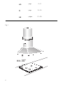
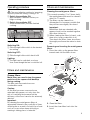
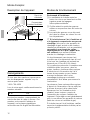
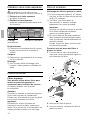
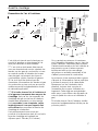
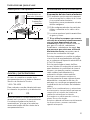
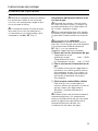
Lighting
Light / fan
switches
Filter grill
Chimney
cover
Operation
❑ The hood fan extracts the kitchen
vapours and conveys them through the
grease filter into the atmosphere.
❑ The grease filter absorbs the solid
particles in the kitchen vapors.
❑ The kitchen is kept almost free of grease
and odors.
D
If the hood is in exhaust-air mode
and a flue-type heater is running at the
same time (e.g. gas, oil or solid-fuel
heaters, continuous-flow heaters, water
heaters), ensure that the fireplace has an
adequate air supply for combustion.
Safe operation requires that the low air
pressure in the room in which the fireplace
is located does not exceed 4 Pa (0.04
mbar).
This low air pressure can be obtained,
provided combustion air can escape
through non-lockable openings, e.g. in
doors, windows, air-intake/exhaust-air wall
boxes or by other technical procedures,
such as reciprocal interlocking, etc.
An air-intake/exhaust-air wall box by itself is
no guarantee that the limiting value will not
be exceeded.
Note: When assessing the air pressure, the
entire ventilation system in the house/
apartment must be taken into account. If
using cooking appliances, e.g. hob and/or
gas cooker, this rule does not apply.
Government regulations must be observed
for the conveyance of exhaust air.
If you encounter a problem
If you have any questions or if a fault
occurs, please call Customer Service:
1-800-735-4328
When you call, please quote the following:
E-Nr. FD
Enter the relevant numbers into the box
above. The E-Nr. (product no.) and FD
(production date) are shown on the
nameplate which can be seen inside the
extractor hood after the filter frame has
been detached.
Appliance description
Instructions for use:

4
Before using for the first time
Important notes:
❑ The Instructions for Use apply to several
versions of this appliance. Accordingly,
you may find descriptions of individual
features that do not apply to your
specific appliance.
❑ This hood complies with all
relevant safety regulations.
Repairs should only be carried out by
qualified technicians.
Improperly executed repairs can give
rise to significant hazards for the user.
❑ Before using your new appliance, please
read these Instructions for Use carefully.
They contain important information
concerning your personal safety as well
as on use and care of the appliance.
❑ Please keep the operating and
installation instructions in a safe place;
this important documentation may also
be of use to a possible subsequent
owner.
Do not use the appliance if it is
damaged in any way
The appliance is not intended for use
by young children without supervision.
Young children should be supervised to
ensure they do not play with the appliance.
Electrical connections should be made
by a qualified technician.
Dispose of packaging materials
properly (see Installation instructions).
Light bulbs must always be fitted when
the hood is in use.
Never operate the hood without a
grease filter.
Overheated fat or oil can easily catch
fire.
If you are cooking with fat or oil, e.g. chips,
etc., never leave food unattended.
Do not flambé food directly under the
hood.
Risk of grease filter catching fire due
! to flames.
WARNING – TO REDUCE THE RISK OF
INJURY TO PERSONS, IN THE EVENT
OF A RANGE TOP GREASE FIRE,
OBSERVE THE FOLLOWING:
SMOTHER FLAMES with a close-fitting
lid, cookie sheet, or other metal tray, then
turn off the gas burner or the electric ele-
ment. BE CAREFUL TO PREVENT BURNS.
If the flames do not go out immediately,
EVACUATE AND CALL THE FIRE DEPART-
MENT
NEVER PICH UP A FLAMING PAN –
you may be burned.
DO NOT USE WATER, including wet
dishclothes or towels – a violent steam
explosion may result.
Use an extinguisher ONLY if:
1. You know you have a class ABC extin-
guisher, and you already know how to
operate it.
2. The fire is small and contained in the
area where it started.
3. The fire department is being called.
4. You can fight the fire with your back to
an exit,

5
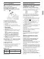
Cleaning the metal grease filters:
❑ In normal operation (1 to 2 hours daily),
the metal grease filter must be cleaned
after 8 to 10 weeks.
❑ The filters can be cleaned in a
dishwasher. It is however possible that
they will become slightly discolored.
Important:
Metal filters that are saturated with
grease should not be washed together
with other dishes etc.
❑ When cleaning the filters by hand, soak
them in hot soapy water first of all.
Then brush the filters clean, rinse them
thoroughly and leave the water to drain
off.
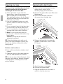
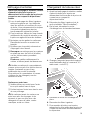
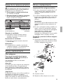
Removing and inserting the metal grease
filters:
1. Press the catch on the grease filters
inwards and fold the filters down.
Filters and maintenance
Filters and maintenance
Grease filters:
Metal filters are used to trap the grease
particles of the vapours that develop
during cooking.
The filter mats are made from non-
combustible metal.
Caution:
As the filter becomes more and more
saturated with grease, not only does the
risk of it catching fire increase but the
efficiency of the hood can also be adversely
affected.
Important:
By cleaning the metal grease filters at
appropriate intervals, the possibility of them
catching fire as a result of a build-up of heat
such as occurs when deep-fat frying or
roasting is taking place, is reduced.
The most effective method of removing
vapours produced during cooking is to:
❑ Switch the ventilator ON
approximately 5 minutes before you
begin cooking.
❑ Switch the ventilator OFF
a few minutes after you have finished
cooking.
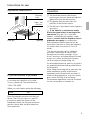
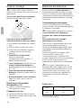
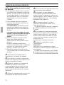
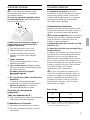
Operating procedure
Switching ON:
❑ Slide the right slide switch to the desired
fan setting.
Switching OFF:
❑ Slide the right slide switch back to 0.
Lighting:
❑ The light can be switched on at any
time, even though the fan is switched off.
1
2
3
Light Off/On
Ventilator settings
2. Clean the filters.
3. Insert the clean filters back into the
hood.

6
Replacing the light bulbsCleaning and care
Disconnect the hood from the electricity
supply by pulling out the AC plug or
switching it off at the fuse box.
❑ At the same time as you clean the
grease filters, clean off any grease from
all accessible parts of the housing.
This significantly reduces the fire hazard
and ensures that the hood performs as
effectively as possible.
❑ Use a hot detergent solution or a mild
window cleaner to clean the canopy of
the hood.
❑ Do not scrape off any dirt that has dried
on but loosen it up with a damp cloth.
❑ Do not use abrasive cleaning agents or
sponges that could cause scratches.
❑ Note: Do not use alcohol (spirit) on
plastic parts, otherwise the surface may
lose its glass.
Caution: Ensure that the kitchen is
adequately ventilated.
Clean the sliding switch with a soft,
damp cloth (mild detergent solution) only.
Do not use stainless steel polish on the
sliding switch.
Stainless steel surfaces:
❑ Use a mild non-abrasive stainless steel
cleaner.
❑ Clean the surface in the same direction
as it has been ground and polished.
Do not use any of the following to clean
stainless steel surfaces: abrasive sponges,
cleaning agents containing sand, soda,
acid or chloride!
1. Switch off the hood and pull out the
mains plug or switch off the
electricity supply at the fuse box.
2. Remove the grease filters (see Filters and
Maintenance).
3. Press down the bulb cover and
disconnect from the light strip.
5. Attach the lamp cover again.
6. Re-insert the grease filters.
7. Plug the appliance into the mains or
switch it on at the fuse box.
4. Replace the light bulb (commercially
available candle bulbs, max. 40 watt,
E12 base).

7
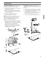
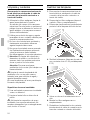
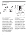
Important information
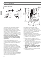
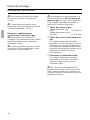
Installation Instructions:
The installation of the hood above
gas cooking devices, at a minimum
height of 30” – Fig. 1 – is permitted
provided that the following
nominal heat loads (Hs) are not exceeded:
❑
Gas cooktops
Load of one burner max. 04,5 kW
Load of all burners max. 14,1 kW
❑
Gas glass-ceramic cooktop
The data on nominal heat loads do not
apply to gas glass-ceramic hotplates.
Be sure to observe the instructions
provided by the manufacturer of the
hotplate.
Always turn hood ON when cooking at
high heat.
Burners should not be operated
without an appropriate cooking vessel in
place over the burners.
Your hood has a thermal overload
which will automatically shut off the motor if
it becomes overheated. The motor will
restart when it cools down. If the motor
continues to shut off and restart, please
have the hood serviced.
The smaller the gap between hood and
cooking appliance, the greater the
likelihood that rising steam will cause
condensation to form on the hood.
Suitable for use in residential cooking
area.
Always mount the hood over the center
of the cooking surface.
Distance between cooking surface and
bottom edge of hood. Should be min 30”
(Fig. 1).
Additional notes concerning cooking
appliances:
The relevant regulations and installation
notes provided by the manufacturer of the
gas cooker must be observed in all cases.
The hood may be installed next to only
one full-height cupboard or high wall.
Gap to be at least 2”.

8
Prior to installation
Exhaust-air mode
The exhaust air is discharged upwards
through a ventilation duct or directly
through the outside wall into the open.
D
Exhaust air should neither be directed
into a smoke or exhaust flue that is
currently used for other purposes, nor into
a shaft that is used for ventilating rooms in
which stoves or fireplaces are also located.
Exhaust air may be discharged in
accordance with official and statutory
regulations only (e.g. national building
regulations).
Local authority regulations must be
observed when discharging air into smoke
or exhaust flues that are not otherwise in
use.
Sufficient air is needed for proper
combustion and exhausting of gases
through the flue (chimney) of fuel burning
equipment to prevent backdrafting. Follow
the heating equipment manufacturers
guideline and safety standards such as
those published by the National Fire
Protection Association (NFPA), the
American Society for Heating, Refrigeration
and Air Conditioning Engineers (ASHRAE),
and the local code authorities.
Note: When assessing the overall
requirement, the combined ventilation
system for the entire household must be
taken into consideration. This rule does not
apply to the use of cooking appliances,
such as hobs and ovens.
All legal requirements concerning the
discharge of exhaust air must be observed.
❑ Due to size and weight of this unit two
installers are recommended.
❑ When cutting or drilling into wall or
ceiling, do not damage electrical wiring
and other hidden utilities.
❑ To properly exhaust air, be sure to duct
air outside – do not vent exhaust air into
spaces within walls, ceilings, attics,
crawl spaces, or garages.
❑ WARNING – TO REDUCE THE RISK
OF FIRE, USE ONLY METAL DUCT
WORK.
❑ Install this hood in accordance with all
requirements specified.
6”
6”
1
18
19
30” / 36”
18
19
45
29”
”
5
8
/
”
1
4
/
”
1
2
/
”
5
8
/
”
7
8
/
”
5
8
/
6
9
”
5
8
/
”
5
8
/
”
1
8
/
2
MAX.
MIN.
MIN.
MIN.

9
Prior to installation
The two lightly sprung flaps must be
able to move upwards
If the exhaust air is going to be
discharged into the open, a telescopic
wall box should be fitted into the outside
wall.
For optimum hood efficiency:
❑ Short, smooth air exhaust duct.
❑ As few bends in the duct run as
possible.
❑ Diameter of duct to be as large as
possible and no tight bends in duct run.
❑ Round pipes:
We recommend
Internal diameter: 6”.
❑ Flat ducts must have an internal cross-
section that equates to that of round
pipes.
There should be no sharp bends.
minimum 3
1
/
4
” x 10” recommended.
❑ If pipes have different diameters:
Insert appropriate transition pieces.
❑ Always ensure that there is an adequa-
te supply of fresh air.
Connecting a l 6” exhaust-air pipe:
❑ Mount the pipe directly onto the air
outlet on the hood.
Preparing the wall
❑ The wall must be flat and perpendicular.
❑ Ensure that the wall is capable of
providing a firm hold for mounting
screws and plugs.
Weight in lbs:
2830”
36” 31
We reserve the right to change specifications or design
without prior notice.
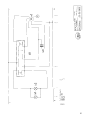
Electrical connection
WARNING: THIS APPLIANCE MUST BE
CONNECTED TO GROUND
IMPORTANT: Fitting a Different Plug:
The wires in the power lead are coloured in
accordance with the following code:
Green – Ground
White – Neutral
Black – Live
If you fit your own plug, the colours of
these wires may not correspond with the
identifying marks on the plug terminals.
This is what you have to do:
1. Connect the green (Ground) wire to the
terminal in the plug marked ‘E’ or with
the symbol ( ).
2. Connect the white (Neutral) wire to the
terminal in the plug marked ‘N’.
3. Connect the black (Live) wire to the
terminal marked ‘L’.
The hood should only be connected to an
earthed socket that has been installed
according to relevant
regulations.
If possible, site the earthed socket directly
behind the chimney panelling.
Electrical data:
Are to be found on the name plate inside
the appliance after removal of the filter
frame.
Before undertaking any repairs,
always disconnect the hood from the
electricity supply.
Length of the connecting cable: 4 ft.
If it is necessary to wire the hood
directly into the mains:
The hood should only be connected to the
electricity supply by a properly qualified
electrician.
A separator must be installed in the house-
hold circuit. A suitable separator is a switch
that has a contact gap of more than 3 mm
and interrupts all poles. Such devices inclu-
de circuit breakers and contactors.
If the connecting cable for this
appliance is damaged, the cable must be
replaced by the manufacturer or his
customer service or a similarly qualified
person in order to prevent serious injury to
the user.

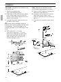
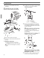
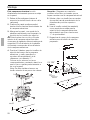
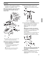
Installation
Note: Take into account any special
accessories that are going to be fitted.
5. Screw on the 2 brackets for fixing the
upper and lower flue ducts.
6. In order to help fix the hood onto the
wall, screw in the middle screw
(without a washer) until it protrudes by
approx.
1
/
4
”.
7. Hook the hood over the screw in the
wall.
9”
9”
1
18
15
2
4
”
5
8
/
”
1
4
/
”
1
2
/
”
1
16
/
”
5
8
/
”
3
4
/
MIN.
30”
8
1
”
1
5
/
CA. 7/32”
This hood is intended to be mounted onto
the kitchen wall.
1. Remove the grease filter
(see operating instructions).
2. Draw a line on the wall from the ceiling
to the lower edge of the hood at the
center of the location where the hood is
going to be mounted.
3. Using the template, mark positions on
the wall for the screws.
Ensure that the minimum distance
between the cooking surface and the hood
is maintained. The bottom edge of the
template equates to the lower edge of the
hood.
4. Drill 5 holes (dia.
1
/
4
”) for the
hood and 4 holes (dia.
1
/
4
”) for the
brackets for fixing the flue ducts and
insert wall plugs flush with the wall.
Note: At least one screw must be
installed through a stud.
10

11
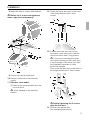
08. Insert the other 4 screws with washers.
Before the 4 screws are tightened
down, align the hood properly.
09. Connect up the air outlet pipe.
10. Connect the hood to the electricity
supply.
11. Stainless steel model:
❑ Remove the protective film from the
two flue ducts.
Avoid damage to the sensitive
surface.
Installation
12. Screw the upper flue duct to the sides
of the fixing bracket with 2 short
screws.
13. Position the lower flue duct on the
hood and screw the hood to the flue
duct from below with 2 long screws.
To prevent scratching the upper
duct when pushing on the lower duct,
cover the edge of the lower duct with
the installation template or other
protective material.
Then screw the flue duct to the sides of
the fixing bracket with 2 short screws.
Before tightening the 2 screws,
align the flue duct.
14. Re-insert the grease filter
(see operating instructions).
1.
2.
Page is loading ...
Page is loading ...
Page is loading ...
Page is loading ...
Page is loading ...
Page is loading ...
Page is loading ...
Page is loading ...
Page is loading ...
Page is loading ...
Page is loading ...
Page is loading ...
Page is loading ...
Page is loading ...
Page is loading ...
Page is loading ...
Page is loading ...
Page is loading ...
Page is loading ...
Page is loading ...

5750 204 499
Printed in Germany 0405 Es.
Robert Bosch Hausgeräte GmbH
-
 1
1
-
 2
2
-
 3
3
-
 4
4
-
 5
5
-
 6
6
-
 7
7
-
 8
8
-
 9
9
-
 10
10
-
 11
11
-
 12
12
-
 13
13
-
 14
14
-
 15
15
-
 16
16
-
 17
17
-
 18
18
-
 19
19
-
 20
20
-
 21
21
-
 22
22
-
 23
23
-
 24
24
-
 25
25
-
 26
26
-
 27
27
-
 28
28
-
 29
29
-
 30
30
-
 31
31
-
 32
32


Bosch DKE9305AUC/02 Operating instructions
- Category
- Cooker hoods
- Type
- Operating instructions
- This manual is also suitable for
Ask a question and I''ll find the answer in the document
Finding information in a document is now easier with AI
in other languages
- français: Bosch DKE9305AUC/02 Mode d'emploi
- español: Bosch DKE9305AUC/02 Instrucciones de operación
Related papers
-
Bosch DKE 93 Serie User manual
-
-
Bosch DKE745K/01 User manual
-
-
-
-
-
Bosch DKE735F/01 Owner's manual
-
Bosch DKE745F/01 Owner's manual
-
Bosch DWA092550/01 Owner's manual
Other documents
-
BALAY 3BD764B/08 User manual
-
-
-
-
-
Siemens LC 47955 User manual
-
Siemens LC45751 Owner's manual
-
-
-
Thermador HMCN36FS User manual