Dell OptiPlex 745c Quick start guide

Category
Mixer/food processor accessories
Type
Quick start guide
www.dell.com | support.dell.com
Dell™ OptiPlex™ 745c
Quick Reference Guide
Model DCSM
Notes, Notices, and Cautions
NOTE: A NOTE indicates important information that helps you make better use of your computer.
NOTICE: A NOTICE indicates potential damage to hardware or loss of data and tells you how to avoid the problem.
CAUTION: A CAUTION indicates a potential for property damage, personal injury, or death.
If you purchased a Dell™ n Series computer, any references in this document to Microsoft
®
Windows
®
operating systems are not applicable.
____________________
Information in this document is subject to change without notice.
© 2007 Dell Inc. All rights reserved.
Reproduction in any manner whatsoever without the written permission of Dell Inc. is strictly forbidden.
Trademarks used in this text: Dell, the DELL logo, and OptiPlex are trademarks of Dell Inc.; Intel is registered trademarks of Intel Corporation;
Microsoft, Windows, and Vista are registered trademarks of Microsoft Corporation.
Other trademarks and trade names may be used in this document to refer to either the entities claiming the marks and names or their products.
Dell Inc. disclaims any proprietary interest in trademarks and trade names other than its own.
Model DCSM
February 2007 P/N PJ175 Rev. A00
Contents 3
Contents
Finding Information . . . . . . . . . . . . . . . . . . . . . . . . . . . . . . . . 5
System Views
. . . . . . . . . . . . . . . . . . . . . . . . . . . . . . . . . . . 8
Mini Tower Computer — Front View
. . . . . . . . . . . . . . . . . . . . . 8
Mini Tower Computer — Back View
. . . . . . . . . . . . . . . . . . . . 10
Mini Tower Computer — Back-Panel Connectors
. . . . . . . . . . . . . 11
Removing the Computer Cover
. . . . . . . . . . . . . . . . . . . . . . . . . . 13
Before You Begin
. . . . . . . . . . . . . . . . . . . . . . . . . . . . . . 13
Mini Tower Computer
. . . . . . . . . . . . . . . . . . . . . . . . . . . . 14
Inside Your Computer
. . . . . . . . . . . . . . . . . . . . . . . . . . . . . . 16
Mini Tower Computer
. . . . . . . . . . . . . . . . . . . . . . . . . . . . 16
Setting Up Your Computer
. . . . . . . . . . . . . . . . . . . . . . . . . . . . 19
Set Up Your Keyboard and Mouse
. . . . . . . . . . . . . . . . . . . . . 20
Set Up Your Monitor
. . . . . . . . . . . . . . . . . . . . . . . . . . . . 20
Power Connections
. . . . . . . . . . . . . . . . . . . . . . . . . . . . . 21
Solving Problems
. . . . . . . . . . . . . . . . . . . . . . . . . . . . . . . . 21
Dell Diagnostics
. . . . . . . . . . . . . . . . . . . . . . . . . . . . . . . 21
System Lights
. . . . . . . . . . . . . . . . . . . . . . . . . . . . . . . . 24
Diagnostic Lights
. . . . . . . . . . . . . . . . . . . . . . . . . . . . . . 25
Beep Codes
. . . . . . . . . . . . . . . . . . . . . . . . . . . . . . . . . 27
Resolving Software and Hardware Incompatibilities
. . . . . . . . . . . 28
Using Microsoft Windows XP System Restore
. . . . . . . . . . . . . . . 28
Reinstalling Microsoft Windows XP
. . . . . . . . . . . . . . . . . . . . 30
Microsoft
®
Windows Vista™. . . . . . . . . . . . . . . . . . . . . . . . 32
The support.dell.com user interface may vary depending
on your selections.
. . . . . . . . . . . . . . . . . . . . . . . . . . . . . . . . 34
Using the Drivers and Utilities CD
. . . . . . . . . . . . . . . . . . . . . . . . 34
Drivers for Your Computer
. . . . . . . . . . . . . . . . . . . . . . . . . 34
Index . . . . . . . . . . . . . . . . . . . . . . . . . . . . . . . . . . . . . . . . . 35
Quick Reference Guide 5
Finding Information
NOTE: Some features or media may be optional and may not ship with your computer. Some features or media may
not be available in certain countries.
NOTE: Additional information may ship with your computer.
What Are You Looking For? Find It Here
A diagnostic program for my computer
Drivers for my computer
My computer documentation
My device documentation
Desktop System Software (DSS)
Drivers and Utilities CD (ResourceCD)
NOTE: The Drivers and Utilities CD may be optional
and may not ship with your computer.
Documentation and drivers are already installed on
your computer. You can use the CD to reinstall
drivers (see "Using the Drivers and Utilities CD" on
page 34), run the Dell Diagnostics (see "Dell
Diagnostics" on page 21), or access your
documentation.
Readme files may
be included on your
CD to provide last-
minute updates
about technical
changes to your
computer or
advanced technical
reference material
for technicians or
experienced users.
NOTE: Drivers and documentation updates can be
found at support.dell.com.
How to remove and replace parts
Specifications
How to configure system settings
How to troubleshoot and solve problems
Dell™ OptiPlex™ User’s Guide
Microsoft Windows XP Help and Support Center
1
Click
Start
Help and Support
Dell User and
System Guides
System Guides
.
2
Click the
User’s Guide
for your computer.
The User’s Guide is also available on the optional
Drivers and Utilities CD.
6 Quick Reference Guide
Warranty information
Terms and Conditions (U.S. only)
Safety instructions
Regulatory information
Ergonomics information
End User License Agreement
Dell™ Product Information Guide
How to reinstall my operating system
Operating System CD
NOTE: The Operating System CD may be optional and
may not ship with your computer.
The operating system is already installed on your
computer. To reinstall your operating system, use
the Operating System CD (see "Reinstalling
Microsoft Windows XP" on page 30).
After you reinstall
your operating
system, use the
optional Drivers and
Utilities CD
(ResourceCD) to
reinstall drivers for
the devices that
came with your
computer. For more
information, see
"Drivers and Utilities CD (ResourceCD)" on page 5.
Your operating system product key label is located
on your computer (see "Service Tag and Microsoft
®
Windows
®
Product Key" on page 7).
NOTE: The color of your Operating System CD varies
according to the operating system you ordered.
How to use Windows XP
How to work with programs and files
How to personalize my desktop
Windows Help and Support Center
1
Click
Start
Help and Support
.
2
Type a word or phrase that describes your problem
and click the arrow icon.
3
Click the topic that describes your problem.
4
Follow the instructions on the screen.
What Are You Looking For? Find It Here
Quick Reference Guide 7
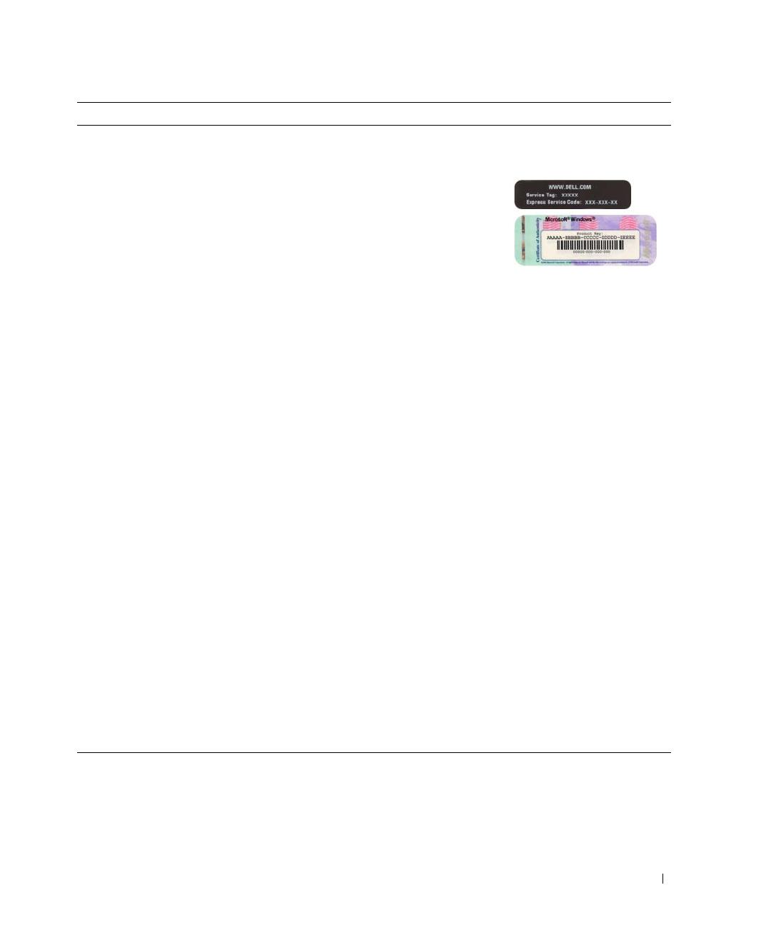
Service Tag and Express Service Code
Microsoft Windows Product Key Label
Service Tag and Microsoft
®
Windows
®
Product Key
These labels are located on your computer.
Use the Service
Tag to identify
your computer
when you use
support.dell.co
m
or contact
support.
Enter the Express Service Code to direct your call
when contacting support.
Solutions — Troubleshooting hints and tips, articles
from technicians, online courses, and frequently asked
questions
Community — Online discussion with other Dell
customers
Upgrades — Upgrade information for components, such
as the memory, hard drive, and operating system
Customer Care — Contact information, service call and
order status, and warranty and repair information
Service and support — Service call status, support
history, service contract, and online discussions with
support
Reference — Computer documentation, details on my
computer configuration, product specifications, and
white papers
Downloads — Certified drivers, patches, and software
updates
Desktop System Software (DSS)— If you reinstall the
operating system on your computer, you should also
reinstall the DSS utility. DSS automatically detects your
computer and operating system and installs the updates
appropriate for your configuration, providing critical
updates for your operating system and support for Dell™
3.5-inch USB floppy drives, Intel
®
processors, optical
drives, and USB devices. DSS is necessary for correct
operation of your Dell computer.
Dell Support Website — support.dell.com
NOTE: Select your region or business segment to
view the appropriate support site.
To download Desktop System Software:
1
Go to
support.dell.com
, select your region or
business segment, then enter your Service Tag.
2
Select
Drivers & Downloads
, then click
Go
.
3
Click your operating system, and then search for
the keyword
Desktop System Software
.
NOTE: The support.dell.com user interface may vary
depending on your selections.
What Are You Looking For? Find It Here
8 Quick Reference Guide
System Views
Mini Tower Computer — Front View
3
11
10
6
7
2
8
5
4
1
9
Quick Reference Guide 9
1 5.25-inch drive bay Can contain an optical drive. Insert a CD or DVD (if supported) into this drive.
2 5.25-inch drive bay Can contain an optical drive. Insert a CD or DVD (if supported) into this drive.
3 3.5-inch drive bay Can contain an optional floppy drive or optional media card reader.
4 USB 2.0 connectors (2) Use the front USB connectors for devices that you connect occasionally, such as
joysticks or cameras, or for bootable USB devices (see your online User’s Guide
for more information on booting to a USB device).
It is recommended that you use the back USB connectors for devices that
typically remain connected, such as printers and keyboards.
5 LAN indicator light This light indicates that a LAN (local area network) connection is established.
6 diagnostic lights Use the lights to help you troubleshoot a computer problem based on the
diagnostic code. For more information, see "Diagnostic Lights" on page 25.
7 power button Press this button to turn on the computer.
NOTICE: To avoid losing data, do not turn off the computer by pressing the
power button. Instead, perform an operating system shutdown. See "Before
You Begin" on page 13 for more information.
NOTICE: If your operating system has ACPI enabled, when you press the
power button the computer will perform an operating system shutdown.
8 power light The power light illuminates and blinks or remains solid to indicate different
operating modes:
No light — The computer is turned off.
Steady green — The computer is in a normal operating state.
Blinking green — The computer is in a power-saving mode.
Blinking or solid amber — See
your online User’s Guide
.
To exit from a power-saving mode, press the power button or use the keyboard or
the mouse if it is configured as a wake device in the Windows Device Manager.
For more information about sleep modes and exiting from a power-saving mode,
see your online User’s Guide.
See "System Lights" on page 24 for a description of light codes that can help you
troubleshoot problems with your computer.
9 hard-drive activity light This light flickers when the hard drive is being accessed.
10 headphone connector Use the headphone connector to attach headphones and most kinds of speakers.
11 microphone connector Use the microphone connector to attach a microphone.
10 Quick Reference Guide
Mini Tower Computer — Back View
4
3
5
6
2
1
Quick Reference Guide 11
Mini Tower Computer — Back-Panel Connectors
1 cover-release latch This latch allows you to open the computer cover.
2 padlock ring Insert a padlock to lock the computer cover.
3 voltage selection switch Your computer is equipped with a manual voltage-selection switch.
To help avoid damaging a computer with a manual voltage-selection switch, set
the switch for the voltage that most closely matches the AC power available in
your location.
NOTICE: The voltage selection switch must be set to the 115-V position even
though the AC power available in Japan is 100 V.
Also, ensure that your monitor and attached devices are electrically rated to
operate with the AC power available in your location.
4 power connector Insert the power cable.
5 back-panel connectors Plug serial, USB, and other devices into the appropriate connectors (see "Mini
Tower Computer — Back-Panel Connectors" on page 11).
6 card slots Access connectors for any installed PCI and PCI Express cards.
13
98 7
5
6
24
12 Quick Reference Guide
1 parallel connector Connect a parallel device, such as a printer, to the parallel connector. If you have a
USB printer, plug it into a USB connector.
NOTE: The integrated parallel connector is automatically disabled if the computer
detects an installed card containing a parallel connector configured to the same
address. For more information, see your online User’s Guide.
2 link integrity light
Green — A good connection exists between a 10-Mbps network and the
computer.
Orange — A good connection exists between a 100-Mbps network and the
computer.
Yellow — A good connection exists between a 1-Gbps (or 1000-Mbps) network
and the computer.
Off — The computer is not detecting a physical connection to the network.
3 network adapter
connector
To attach your computer to a network or broadband device, connect one end of a
network cable to either a network jack or your network or broadband device.
Connect the other end of the network cable to the network adapter connector on
the back panel of your computer. A click indicates that the network cable has been
securely attached.
NOTE: Do not plug a telephone cable into the network connector.
On computers with a network connector card, use the connector on the card.
It is recommended that you use Category 5 wiring and connectors for your
network. If you must use Category 3 wiring, force the network speed to 10 Mbps to
ensure reliable operation.
4 network activity light Flashes a yellow light when the computer is transmitting or receiving network
data. A high volume of network traffic may make this light appear to be in a steady
"on" state.
5 line-out connector Use the green line-out connector to attach most speakers with integrated
amplifiers.
6 line-in/microphone
connector
Use the blue and pink line-in/microphone connector to attach a record/playback
device such as a cassette player, CD player, or VCR.; or a personal computer
microphone for voice or musical input into a sound or telephony program.
7 USB 2.0 connectors (6) Use the back USB connectors for devices that typically remain connected, such as
printers and keyboards.
8 video connector Plug the cable from your VGA-compatible monitor into the blue connector.
NOTE: If you purchased an optional graphics card, this connector will be covered by
a cap. Connect your monitor to the connector on the graphics card. Do not remove
the cap.
NOTE: If you are using a graphics card that supports dual monitors, use the y-cable
that came with your computer.
9 serial connector Connect a serial device, such as a handheld device, to the serial port. The default
designations are COM1 for serial connector 1 and COM2 for serial connector 2.
For more information, see your online User’s Guide.
Quick Reference Guide 13
Removing the Computer Cover
CAUTION: Before you begin any of the procedures in this section, follow the safety instructions in the
Product Information Guide.
CAUTION: To guard against electrical shock, always unplug your computer from the electrical outlet before
removing the cover.
Before You Begin
NOTICE: To avoid losing data, save and close any open files and exit any open programs before you turn off
your computer.
1
Shut down the operating system:
a
Save and close any open files, exit any open programs, click the
Start
button, and then click
Turn Off Computer
.
b
In the
Turn off computer
window, click
Turn off
.
The computer turns off after the operating system shutdown process finishes.
2
Ensure that the computer and any attached devices are turned off. If your computer and attached
devices did not automatically turn off when you shut down your operating system, turn them off now.
Before Working Inside Your Computer
Use the following safety guidelines to help protect your computer from potential damage and to help
ensure your own personal safety.
CAUTION: Before you begin any of the procedures in this section, follow the safety instructions in the
Product Information Guide.
CAUTION: Handle components and cards with care. Do not touch the components or contacts on a card. Hold a
card by its edges or by its metal mounting bracket. Hold a component such as a processor by its edges, not by
its pins.
NOTICE: Only a certified service technician should perform repairs on your computer. Damage due to servicing
that is not authorized by Dell is not covered by your warranty.
NOTICE: When you disconnect a cable, pull on its connector or on its strain-relief loop, not on the cable itself.
Some cables have a connector with locking tabs; if you are disconnecting this type of cable, press in on the locking
tabs before you disconnect the cable. As you pull connectors apart, keep them evenly aligned to avoid bending any
connector pins. Also, before you connect a cable, ensure that both connectors are correctly oriented and aligned.
To avoid damaging the computer, perform the following steps before you begin working inside the
computer.
1
Turn off your computer.
NOTICE: To disconnect a network cable, first unplug the cable from your computer and then unplug it from the
network wall jack.
2
Disconnect any telephone or telecommunication lines from the computer.
14 Quick Reference Guide
3
Disconnect your computer and all attached devices from their electrical outlets, and then press the
power button to ground the system board.
4
If applicable, remove the computer stand (for instructions, see the documentation that came with the
stand).
CAUTION: To guard against electrical shock, always unplug your computer from the electrical outlet before
removing the cover.
5
Remove the computer cover. See "Mini Tower Computer" on page 14.
NOTICE: Before touching anything inside your computer, ground yourself by touching an unpainted metal surface,
such as the metal at the back of the computer. While you work, periodically touch an unpainted metal surface to
dissipate any static electricity that could harm internal components.
Mini Tower Computer
CAUTION: Before you begin any of the procedures in this section, follow the safety instructions in the
Product Information Guide.
CAUTION: To guard against electrical shock, always unplug your computer from the electrical outlet before
removing the computer cover.
1
Follow the procedures in "Before You Begin" on page 13.
2
Lay the computer on its side as shown in the illustration.
3
Locate the cover release latch shown in the illustration. Then, slide the release latch back as you lift the
cover.
4
Grip the sides of the computer cover and pivot the cover up using the hinge tabs as leverage points.
5
Remove the cover from the hinge tabs and set it aside on a soft nonabrasive surface.
CAUTION: Graphic card heatsinks may become very hot during normal operation. Ensure that a graphic card
heatsink has had sufficient time to cool before you touch it.
Quick Reference Guide 15
1 security cable slot 2 cover release latch 3 padlock ring
2
1
3
16 Quick Reference Guide
Inside Your Computer
Mini Tower Computer
1 optical drive 2 floppy drive 3 power supply
4 chassis-intrusion switch 5 system board 6 heat-sink assembly
7 hard drive
1
3
5
4
7
2
6
Quick Reference Guide 17
System Board Components
MFG_MODE
1
2
4
7
15
9
16
17
10
5
6
3
11
12
19
20
18
21
14
13
8
18 Quick Reference Guide
Jumper Settings
NOTE: Do not populate the MFG_MODE jumper. Active Management technology will not function properly. Only
manufacturing uses this jumper.
1 fan connector (FAN) 12 internal USB (INTERNAL_USB)
2 processor connector (CPU) 13 battery socket (BATT)
3 processor power connector (12VPOWER) 14 PCI Express x16 connector (SLOT1)
4 memory module connectors (DIMM_1, DIMM_2,
DIMM_3, DIMM_4)
15 PCI Express x1 connector (SLOT4)
5 RTC reset jumper (RTCRST) 16 PCI connector (SLOT2)
6 password jumper (PSWD) 17 PCI connector (SLOT3)
7 SATA drive connectors (SATA0, SATA1, SATA4, SATA5) 18 serial connector (SER2)
8 manufacturing mode jumper (MFG_MODE) 19 floppy drive connector (DSKT)
9 front-panel connector (FNT_PANEL) 20 system board speaker (BEEP)
10 power connector (POWER) 21 speaker connector (INT_SPKR)
11 intrusion switch connector (INTRUDER)
Jumper Setting Description
PSWD Password features are enabled
(default setting).
Password features are
disabled.
RTCRST The real-time clock has
not been reset.
The real-time clock is being reset
(jumpered temporarily).
jumpered unjumpered
Quick Reference Guide 19
Setting Up Your Computer
CAUTION: Before performing any of the procedures in this section, follow the safety instructions in
Product Information Guide.
NOTICE: If your computer has an expansion card installed (such as a modem card), connect the appropriate cable
to the card, not to the connector on the back panel.
NOTICE: To help allow the computer to maintain proper operating temperature, ensure that you do not place the
computer too close to a wall or other storage compartment that might prevent air circulation around the chassis.
See your Product Information Guide for more information.
NOTE: Before you install any devices or software that did not ship with your computer, read the documentation
that came with the device or software, or contact the vendor to verify that the device or software is compatible
with your computer and operating system.
You must complete all the steps to properly set up your computer. See the appropriate figures that follow
the instructions.
NOTICE: Do not attempt to operate a PS/2 mouse and a USB mouse simultaneously.
1
Connect the keyboard and mouse.
NOTICE: Do not connect a modem cable to the network adapter connector. Voltage from telephone
communications can cause damage to the network adapter
2
Connect the modem or network cable.
Insert the network cable, not the telephone line, into the network connector. If you have an optional
modem, connect the telephone line to the modem.
3
Connect the monitor.
Align and gently insert the monitor cable to avoid bending connector pins. Tighten the thumbscrews
on the cable connectors.
NOTE: Some monitors have the video connector underneath the back of the screen. See the documentation
that came with your monitor for its connector locations.
4
Connect the speakers.
5
Connect power cables to the computer, monitor, and devices and connect the other ends of the power
cables to electrical outlets.
NOTICE: To avoid damaging a computer with a manual voltage-selection switch, set the switch for the voltage that
most closely matches the AC power available in your location.
NOTICE: In Japan, the voltage selection switch must be set to the 115-V position even though the AC power
available in Japan is 100 V.
6
Verify that the voltage selection switch is set correctly for your location.
Your computer has a manual voltage-selection switch. Computers with a voltage selection switch on
the back panel must be manually set to operate at the correct operating voltage.
20 Quick Reference Guide
Set Up Your Keyboard and Mouse
Set Up Your Monitor
Quick Reference Guide 21
Power Connections
Solving Problems
Dell provides a number of tools to help you if your computer does not perform as expected. For the latest
troubleshooting information available for your computer, see the Dell Support website at
support.dell.com.
If computer problems occur that require help from Dell, write a detailed description of the error, beep
codes, or diagnostics light patterns, record your Express Service Code and Service Tag below, and then
contact Dell from the same location as your computer. For information on contacting Dell, see your
online User’s Guide.
For an example of the Express Service Code and Service Tag, see "Finding Information" in your computer
User’s Guide.
Express Service Code: ___________________________
Service Tag: ___________________________
Dell Diagnostics
CAUTION: Before you begin any of the procedures in this section, follow the safety instructions in the
Product Information Guide.
When to Use the Dell Diagnostics
If you experience a problem with your computer, perform the checks in "Solving Problems" in your online
User’s Guide and run the Dell Diagnostics before you contact Dell for technical assistance. For
information on contacting Dell, see your online User’s Guide.
NOTICE: The Dell Diagnostics works only on Dell™ computers.
1 / 1

Dell OptiPlex 745c Quick start guide

Category
Mixer/food processor accessories
Type
Quick start guide

Ask a question and I''ll find the answer in the document

Finding information in a document is now easier with AI

Ask the document