Page is loading ...

1
SB-E-2-CBA1 ISS.02
Operation Manual
Viper – Automatic Spray Gun
E P 1 – 12

2
Operation Manual
Viper- Automatic Spraygun
Important
Read and follow all instructions and Safety Precautions before using this equipment
CHARACTERISTICS
Automatic Spray gun for enamel application designed to give you the optimal production performance.
This spray gun is answering the needs of the sanitary application, table ware and decorative
application, pavement, tiles, electric domestic appliances and all others ceramic activities.
The patent pending “Quick Up” ring will give you an easy and quick dissembling of the air cap and the
tip. The patent pending bellows seal will give your needle long life.
The needle adjustment knob has 18 ratchet positions, allows fine and accurate fluid flow control.
MATERIALS OF CONSTRUCTION
Gun body Aluminium hard anodizing
Tip
With brass body
assy
Stainless steel 303. (Option only)
Stainless steel hardened HRC 58 & Nickel treated.
Carbide.
Needle
Stainless steel 303 body & needle end. (Option only)
Stainless steel body & needle end Steel hardened to HRC 58
Stainless steel body & carbide end.
Stainless steel body & special PU end (Option only)
Spray head Stainless steel
SPECIFICATIONS
Thread
Pressure
Fluid inlet & Fluid Recirculation “P” 1/4 BSP 7b max
Air inlet (Atom+Fan) “A” “F” 1/4 BSP 7b max
Cylinder/trigger “Cyl” 1/8 BSP 4b min - 7b max
Maximum temperature in use 40° C
Spray gun weight 620 gr
Air consumption E31
E63
E70
340 l/mn at 2.5 bar
450 l/mn at 3.5 bar
540 l/mn at 4 bar
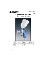
A Adjusting knob
B Head gun
C Baffle
D Air Cap
E Valve
F Body
P Product inlet

3
SAFETY WARNINGS
Fire and explosion
Solvents and coating materials can be highly flammable or combustible when sprayed.
ALWAYS refer to the coating material supplier’s instructions and COSHH sheets
before using this equipment.
Users must comply with all local and national codes of practice and insurance company
requirements governing ventilation, fire precautions, operation and house-keeping of
working areas.
This equipment, as supplied, is NOT suitable for use with Halogenated
Hydrocarbons.
Static electricity can be generated by fluid and/or air passing through hoses, by the
spraying process and by cleaning non- conductive parts with cloths. To prevent ignition
sources from static discharges, earth continuity must be maintained to the spray gun and
other metallic equipment used. It is essential to use conductive air and/or fluid hoses.
Personal Protective Equipment
Toxic vapours – When sprayed, certain materials may be poisonous, create irritation or
are otherwise harmful to health. Always read all labels, safety data sheets and follow any
recommendations for the material before spraying. If in doubt, contact your material
supplier.
The use of respiratory protective equipment is recommended at all times. The type of
equipment must be compatible with the material being sprayed.
Always wear eye protection when spraying or cleaning the spray gun.
Gloves must be worn when spraying or cleaning the equipment.
Training – Personnel should be given adequate training in the safe use of spraying equipment.
Misuse
Never aim a spray gun at any part of the body.
Never exceed the max. Recommended safe working pressure for the equipment.
The fitting of non-recommended or non-original spares may create hazards.
Before cleaning or maintenance, all pressure must be isolated and relieved from the equipment.
The product should be cleaned using a gun-washing machine. However, this equipment should
not be left inside gun-washing machines for prolonged periods of time.
Noise Levels
The A-weighted sound level of spray guns may exceed 85 dB (A) depending on the set-
up being used. Details of actual noise levels are available on request. It is recommended
that ear protection is worn at all times when spraying.
Operating
Spray equipment using high pressures may be subject to recoil forces. Under certain
circumstances, such forces could result in repetitive strain injury to the operator.

4

5
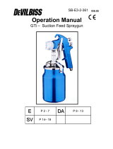
LIST OF SPARE PARTS
For the arrangement of the parts, refer the exploded view
Rep Ref Description Qty
1 SPA-36 Retaining ring 1
2 SPA-17-K5 Gasket Polyurethane kit of 5 1
3
SPA-100-E63
SPA-100-E70
SPA-100-E31
“Conventional” air cap for tips Ø 1.8 & 2.0
“Conventional” air cap for tips Ø 2.2 & 2.8
“Transtech” air cap for tips Ø 1.2 to 2.0
1
4 SPA-16-K2 Gasket kit of 2 1
5
SPA-250H-XX
SPA-250-XX
SPA-254-XX
Tip assy with brass body (see chart p11 combination)
Tip inserted in Stainless steel (1,2 to 2,0) (Option)
Tip inserted steel hardened & Nickeled
(1.2 to 2.8B)
Tip inserted carbide (2,2 or 2,8)
1
6 S-14190-K4 Screw M4 x 25 kit of 4 Torx 20 1
7 S-28218-K5 O ring kit of 5 4
8 SPA-2 Spray head 1
9 SPA-11 Bellows (needle seal) 1
10 SPA-10 Sealing washer 1
11 S-28221-K10 Gasket kit of 10 2
12 SPA-1-VPR Gun body 1
13 AGG-403 Air valve 2
14 S-28220-K5 Gasket kit of 5 1
15 SPA-6-1-K Piston + Gaskets (14, 15a, 16) 1
15a SPA-28225-K5 Gasket kit of 5 1
16 S-28219-K10 Gasket kit of 10 2
17 SPA-13 Piston Spring 1
18
SPA-350-DE
SPA-351-DE
SPA-351-DEH
SPA-351-22
SPA-351-28B
SPA-352
Needle, PU point for tips 1.2 to 2.0 (Option)
Needle, hardened S Steel point, for tips 1.2 to 2.0
Needle, full 303 S. steel for tip SPA-250H-xx (Option)
Needle, hardened S Steel point, for tip 2.2
Needle, hardened S Steel point, for tip 2.8B
Needle, carbide point, for carbide tips 2.2 to 2.8
1
19 SPA-3 Housing 1
20 1
21 SPA-KK-1 Kit of ring and ball for ratchet 3
22 AGMD-110 Spring 1
23 AGMD-111 Spring 1
24 SPA-19 Washer 1
25 SPA-4 Adjusting knob 1
26* SPA-7-K Kit rear housing without adjustment (Option)
27* SPA-22-K2 Kit of air connector for remote control (Option)
28* AGGS-33 Shaft (Accessory)
29* SS-659-CD Nut (Accessory)
30 S-18226 Plug ¼ BSP for spray gun without fluid recirculation 1
31 S-1444-H M5 hexagon socket head cap screw, length 8 2
32 SPA-25 Plug 1
* Optional spare parts

6
Ad
j
ustin
g
knob
Adjusting knob
POSSIBLE COMBINATIONS
Fluid Tip Needle Air Cap
Hardener
Steel Carbide Point
Pu Point
Steel Point Carbide E63 E70 E31
Ø
mm
SPA-250-XX SPA-254-XX SPA-350-XX SPA-351-XX SPA-352 SPA-100-XXX
1.2 12 DE DE
X
1.4 14 DE DE
X
1.6 16 DE DE
X
1.8 18 DE DE
X X
2.0 20 DE DE
X X
2.2 22 22 22 x X
2.8 28B 28 28B x X
Tip SPA-250H-xx (Size 12 to 2,0 mm) and needle SPA-351-DEH in stainless steel 303 will be
supplied only in option.
MODEL PART NUMBER
VPR-E70-28 C
C = Tip/Needle in carbide
Tip Ø (2.8 mm)
Air cap number (E70)
Spray gun type
OPÉRATION
Important : This spray gun is designed for water based application, solvent
is prohibited, it will damage the seal inside the spray gun. To ensure that
this equipment reaches you in first class condition, protective coatings
have been used. Flush the equipment through with water before use.
Connect the air and fluid supply, clean the fluid passage during 3 minutes
and operate trigger piston 10 time at minimum.
SETTING
1. The « ATOM » air valve control the atomizing air pressure
« FAN » reduces the spray pattern size. To increase the
pressure turn clockwise & reverse to reduce turn counter-
clockwise.
2. Fluid flow can be adjusted with the rear ratchet knob, fluid
flow is increased when you turn the knob counter-
clockwise.

7
STARTING-UP
1. Turn the needle adjusting knob clockwise until it.
2. Turn the “Fan” and “Atom air valves counter-clockwise to be full open.
3. Set the air pressure at the air regulator to achieve recommended pressures above.
4. Turn the adjusting knob counter clockwise to obtain the desired fluid flow.
5. Test spray. If the finish is too dry or fine, reduce airflow by reducing air inlet pressure or by the valve
(13 Atom) screwing it in clockwise, or increase fluid flow using ratchet knob rotating counter clockwise.
6. If the finish is too wet, turn the needle button (25) in clockwise to reduce the fluid flow, or reduce the
fluid pressure.
If the atomization is too coarse, increase inlet air pressure, or reduce fluid flow.
7. The pattern size can be reduced by turning adjusting valve “Fan” (13) clockwise.
8. The spray pattern will give the best results when perpendicular to the target.
9. The recommended spray distance is 150-220 mm (6’’ to 8’’).
10. Spray edges first. Overlap each stroke a minimum of 50%. Move gun at a constant speed.
11. Always turn off air and fluid supply and relieve pressure and clean down when gun is not in us.
PREVENTIVE MAINTENANCE
Turn off air and coating supply and relieve pressure in the supply lines, before any maintenance
operation.
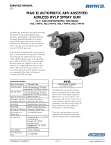
Tip (5) & needle (18)
Remove the air cap and its retaining ring by unscrewing by ¼
turn counter- clockwise (Fig 1).
Remove the tip and its baffle (5) by unscrewing by ¼ turn
counter- clockwise (Fig 2). Unscrew the adjusting needle knob fully
in counter-clockwise rotation and pull out the needle at the back.
After refitting the needle and before refitting the nozzle, push the
bellows (with the tube supplied) back in order to put it in
contact with the needle shoulder so as to make the product
passage free.
The fluid tip and baffle are permanently fitted together. There is no
possibility to separate them. The baffle will be damage if you try to
dismantle.
Tube

8
FIG 1 FIG 2
PACKING
Unscrew the 4 screws to disassemble the gun head. Remove the packing bellows seal. Clean or
replace if the packing is damaged.
FAN & ATOM AIR VALVE (13)
Before assembling, check the air valve is in fully open position by
unscrewing it counter-clockwise.
Piston (15), o ring (16) & (14)
Unscrew the rear housing (19) at the back of the gun body counter
clockwise, pull out the needle (18).
Use bent nose pliers so to pull out the piston which has a 12mm
internal groove for this purpose.
It’s recommended to replace the o ring (14) into the gun body as soon
you disassemble the Piston.
When replacing the piston, slightly lubricate all the O rings before fitting
into the gun body.
PREVENTIVE MAINTENANCE
1. Turn off air and coating supply and relieve pressure in the supply lines, or disconnect from
airline and fluid line.
2. Remove air cap and clean. If any of the holes in the cap are blocked with coating material use
a toothpick to clean. Never use metal wire which could damage the cap and produce
distorted spray patterns
3. Ensure the fluid tip of the nozzle is clean and free from damage especially the outside at the
front diameter. Any build up of dried paint can distort the spray pattern.

9
EC Declaration of Conformity
We, ITW Finishing UK, Ringwood Rd, Bournemouth, Dorset, BH11 9LH, UK, as the manufacturer of the Spray
gun model VIPER , declare, under our sole responsibility that the equipment to which this document relates is in
conformity with the following standards or other normative documents:
BS EN 292-1 PARTS 1 & 2: 1991, BS EN 1953: 1999; and thereby conform to the protection requirements of Council
Directive 98/37/EEC relating to Machinery Safety Directive, and;
EN 13463-1:2001, council Directive 94/9/EC relating to Equipment and Protective Systems intended for use in
Potentially Explosive Atmospheres protection level II 2 G X.
B. Holt, General Manager
24th April 2007
ITW Finishing Systems and Products reserve the right to modify equipment specification without prior notice.
OPTIONS
Spray gun without needle adjustment
Part number: SPA-7-K
This kit includes the back piece and washer to replace the part items 19, 20,
21, 24, 25, on the exploded view.
Spray gun with “Atom” & “fan” remote control
Parts number: SPA-22-K2
This includes 2 connectors taking place of the two 2 air valves (13) on the
exploded view.
Spray gun shaft
Part number: AGGS-33
Nut for spray gun shaft
Part number: SS-659-CD

© 2007 ITW Finishing Systems and Products
10

© 2007 ITW Finishing Systems and Products
11

© 2007 ITW Finishing Systems and Products
12
ITW Finishing Systems and Products
Ringwood Road,
Bournemouth,
BH11 9LH,
England.
Tel. No. (01202) 571111
Telefax No. (01202) 581940,
Website address
http://www.itweuropeanfinishing.com
ITW Oberflächentechnik GmbH & Co.
KG
Justus-von-Liebig-Straße 31
63128 Dietzenbach
Tel (060 74) 403-1
Telefax: (060 74) 403300
Website address
http://www.itw-finishing.de
ITW Automotive Finishing UK
Anchorbrook Industrial Estate
Lockside
Aldridge,
Walsall,
UK.
Tel. No. (01922) 423700
Telefax No. (01922) 423705,
Website address
http://www.itweuropeanfinishing.com
ITW Surfaces Et Finitions
163-171 avenue des Auréats B.P.
1453
26014 VALENCE CEDEX FRANCE
Tél. (33) 475-75-27-00
Télex 345 719F DVILBIS
Téléfax: (33) 475-75-27-99
ITW Finishing Systems and Products is a Division of ITW Ltd. Reg. Office:
Admiral House,
St Leonard’s Road,
Windsor,
Berkshire,
SL4 3BL,
UK
Registered in England: No 559693 Vat No 619 5461 24
/