Page is loading ...

1
SELF POWERED SIMPLICITY
The ultra-low power consumption of the Ditak 5 (60 microwatts) opens up
vast new application possibilities. In a great many cases the pulse signal source
itself has sufficient power content to operate the unit. Alternatively, the Ditak
5 can be equipped with batteries, or power can be supplied from an external
source.
ACCURACY
0.1% crystal controlled accuracy with digital readout provides speed
measuring precision at a low cost.
SEALED FRONT, RUGGED CONSTRUCTION
Housed in a die-cast metal case, designed for NEMA 4/IP65, the unit can be
mounted in tough, industrial environments and withstand oil or water spray.
Micro-assembly construction provides high shock and vibration resistance.
VERSATILITY
Ideal for portable and/or fixed in-plant use. Operates with +5 Volt CMOS and
TTL circuit outputs and is adaptable to electronic sensor outputs.
ADVANTAGES OF MICRO-ELECTRONICS
The Ditak 5 is a state-of the art rate measuring instrument. Its superior
performance/cost ratio sets a new benchmark for the industry. This is made
possible by the technology of micro-electronics.
Micro-electronics concentrates as much circuitry as possible into a few
monolithic LSI chips. The Ditak 5 utilizes two of these custom chips to
encompass more than 99.9% of the required circuit components. These chips
are bonded to a substrate carrier and the microscopic electrical connections are
made by ultrasonically wire-bonding the chip pads to the gold plated conductors
on the substrate. Inter-connections of separate assemblies and components such
as the LCD and batteries are accomplished by elastomeric connectors.
RELIABILITY
Large scale integration achieves the ultimate in circuit reliability. The Ditak
5’s miniature size provides high immunity to shock and vibration damage.
Elastomeric (internal and battery) connections provide gas-tight, corrosion-
proof, sealed contacts for trouble free operation.
SMALL SIZE
Micro-electronics allows the display to become the primary determinator of
size which means cost savings in panel-shape, weight, power consumption, and
functional simplicity.
BEST PERFORMANCE/COST RATIO
Micro-electronics is inherently a highly automated technique which provides
the quality, performance, and features needed at a very low cost.
DESCRIPTION OF OPERATION
The Ditak 5 is a combination of a precision counter and a crystal controlled
1-second time base, with liquid crystal display. In operation, the electronic
counter accumulates incoming pulses for a period of exactly one second. At the
end of this period, the count is transferred and latched on the display.
Immediately after transferring the count to the display, the internal counter is
reset to zero and begins accumulating a new count. Consequently, the display is
updated once a second, and the readout at any one time is the numerical value
of the number of counts received in the previous 1-second interval.
The Ditak 5 is basically a frequency measuring device and can be used for
direct Hz readout. Many industrial rate parameters, however, are expressed in
terms of minutes (gallons/min., feet/min., revolutions/min., etc.) Counting these
units for a full minute before presenting a readout takes too much time and is
therefore impractical. By using a sensor arrangement that delivers 60 pulses/unit
of measure (such as a 60 tooth gear to generate 60 PPR for RPM indication), the
Ditak 5 will read out directly in the desired units with a convenient 1-second
update time.
DITAK 5 - THE ACCURATE, ECONOMIC & EASY WAY TO MEASURE RPM, GPM, FPM . . .
INDICATE PRODUCTION RATE & DISPLAY FREQUENCY
Bulletin No. DT5-E
Drawing No. LP0003
Released 9/01
Tel +1 (717) 767-6511
Fax +1 (717) 764-0839
www.redlion-controls.com

2
Selection of desired inputs and external power is easily
done by adding or moving terminal leads in the Input
Connector Body. The connector body is polarized
to prevent incorrect insertion, and locked in
place by the battery cover to avoid
accidental disengagement. Connectors
are supplied with the 2 leads installed as
shown below. A spare blue lead is
supplied in the hardware pack.
TO REMOVE TERMINAL, insert blade of
a small screwdriver into slot of connector
body, and gently push in to disengage lock
pawl. Pull terminal out.
WHEN INSERTING TERMINAL into connector body, make sure the lock
pawl is toward the slot in the body. Push terminal in until lock pawl snaps
into slot.
Connector Body, MOLEX P/N 2201-2051
Connector Term, MOLEX P/N 08-50-0114
APPLICATION FLEXIBILITY VIA RECONNECT OPTIONS
TYPICAL APPLICATIONS
In this application the Magnetic Pickup supplies both the signal and
operating power for the unit. A diode bridge in the Ditak 5 rectifies the A.C.
waveform generated by the magnetic pickup to develop the +V operating
voltage. The half wave component of this A.C. is applied to the base of the
input transistor to generate count pulses. The Zener Diode (ZD) clamps +V to
6.2 V maximum.
With an MP62TA Magnetic Pickup, a 60-tooth 20 D.P. Gear, and an air gap
of 0.005", the pickup will begin to develop sufficient voltage to power the
Ditak 5 (about 3.5 V peak) at a speed of 175 to 200 RPM. See Magnetic
Pickup and ARCJ Ring Kit tables for typical minimum speed parameters of
various sizes of Magnetic Pickups and ARCJ Rings.
SELF-POWERED FROM MAGNETIC PICKUP SIGNAL (Using MP62TA magnetic pickup, or ARCJ ring pickup kits)
Using batteries or an external source to supply power to the Ditak 5, allows
the magnetic pickup to be used only as a signal source at low speed. By
relocating the connector terminal wires as shown above, the magnetic pickup
voltage is applied directly to the transistor input and a signal level of only 0.7
Volts peak is needed for operation. This reduces minimum operating speed to
about 25% of the level required for self-powered operation (See Mag. Pkup.
and ARCJ Ring tables).
When batteries are used, current is drawn from the battery only during low
speed operation. At high speeds the half-wave rectified magnetic pickup
voltage exceeds the battery voltage and the unit again becomes self-powered,
to extend battery life. (Nominal battery life, without the high speed power
contribution of the magnetic pickup is 3 to 3.5 years).
MAGNETIC PICKUP SIGNAL INPUT WITH BATTERY OR EXTERNAL POWER (For extended low speed performance)
NOTES ON MAGNETIC PICKUPS
1. Magnetic Pickups generate voltage proportional to the size and speed of
passing gear teeth, and inversely proportional to air-gap.
2. Sensing gears used with Magnetic Pickups should run as true as possible.
Eccentricity and wobble causes voltage fluctuations that can produce
observable display “flicker” at low speeds when pickup power is being
used to operate the Ditak 5.
3. Shielded cable is recommended when using magnetic pickups. Connect the
shield to the COMMON input pin of the Ditak 5 (A spare BLUE terminal
wire in the hardware package may be used to bring out COMMON). Leave
the shield unconnected at the sensor end (MP62TA is supplied with shielded
cable, open at the pickup end). The Ditak 5 case should be mounted in a
panel which is electrically grounded through the machine frame to the
pickup housing of the ARCJ Ring motor.
4. Magnetic Pickups have a highly inductive output impedance which limits
output voltage and current to a safe level when clamped by the internal
zener diode in the Ditak 5. Signal sources with peak voltage in excess of 6
Volts, and having low output impedance, may develop sufficient power to
damage the internal zener diode if connected directly. With this type of
signal source, use a current limiting resistor as shown in the following
application.
Note: Connector wire colors shown are arranged
arbitrarily - User can select any color code
scheme desired.

3
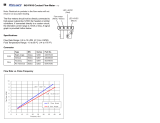
SPECIFICATIONS
1. DISPLAY: 4-digit LCD, 0.35" (9 mm) high
2. POWER SOURCE: Operates from any one of the following:
Signal Source Powered: A.C. or square wave signal inputs with min. peak
voltage of 3.5 V @ 150 µA and min. frequency of 15 Hz will operate the
DITAK 5 without batteries or external power.
Battery Powered: 2, 1.5 V N-type Alkaline Cells can be inserted if
conditions for signal source power cannot be met. Nominal battery life is
3 to 5 years depending on operating conditions.
External Power Input: Operates from external power sources ranging from
+5 VDC @ 35 µA to +24 VDC @ 1.8 mA.
3. TIME BASE: 1-second measuring and display up-date interval. Crystal
controlled to +0.1%, +1 digit accuracy.
4. INPUTS: Accepts A.C. (± polarity swing) signals, or logic pulse inputs. Min.
sensitivity when using batteries or external power is 0.7 V peak. Min.
sensitivity when self-powered is 3.5 V peak. (See POWER SOURCE,
above). Input signal voltages over 6 V peak, require external series resistor to
limit input current to 10 mA max.
5. MAXIMUM INPUT FREQUENCY: 10 KHz, 50 µsec min. pulse width.
6. OPERATING TEMPERATURE RANGE: 0° to 50°C (32° to 122°F)
7. STORAGE TEMPERATURE RANGE: 20° to 60°C (-4° to +140°F)
8. WEIGHT: 5.1 oz. (146 g)
DIMENSIONS & INSTALLATION
After cutting the opening in panel, slide the panel gasket over the rear of the
case to the back of the bezel. Then slide the case through the panel cut-out.
Install mounting clips on each side of counter body with mounting screws.
Make sure the side rails of the clips fit into the recesses in the side of the case
so that the “Tang Ends” wedge between the panel opening and body as the
screws are tightened.
DIMENSIONS In inches (mm)
TYPICAL APPLICATIONS (Cont’d)
A.C. Signal Sources can be used to operate the Ditak 5 via the Magnetic
Pickup Input without batteries or external D.C. power, down to 7 or 8 Hz
signal frequency. However, unlike magnetic pickups most A.C. signal sources
have low output impedance and require a current limiting resistor if the peak
voltage exceeds 6 volts.
Capacitors shown connected to COMMON by dotted lines may be required
when A.C. voltage supply is “noisy”. Capacitor values depend on existing
conditions but values from 0.01 to 0.1 µfd are usually effective. An isolation
step-down transformer should always be used when power line or high
voltage inverter lines and being monitored.
The Ditak 5 easily adapts to a wide variety of pulse signal inputs. The only
restriction that must be kept in mind is that a current limiting resistor must be
used in series with the input applied to “PSM IN” if the input signal voltage
exceeds +6 Volts peak (Limit input current to 10 mA peak). With square wave
inputs (50% duty cycle), at frequencies of 15 Hz and above, the Ditak 5 will
operate directly from the power delivered by the signal itself without batteries
or external power applied. If the signal is a narrow positive going pulse, or if
operation below 15 Hz is required, either external power should be connected
as shown, or batteries should be installed.
VARIABLE FREQUENCY A.C. INPUTS, SIGNAL SOURCE POWERED
LOGIC PULSE INPUTS FROM OTHER CIRCUITS & SENSORS
USE THE DITAK 5 WITH THE MODEL PSMA POWER SUPPLY & INTERFACE MODULE, OR WITH CONVENIENT
ELECTRONIC SENSORS FOR EASY APPLICATION TO YOUR SPECIAL RATE MEASURING PROBLEM.
Minimum V
AC
for operation is 3.2 V peak
Select R to limit input current to 10 mA max. at max. V
AC
.
4.7K resistor required only
when +V is over +6VDC
+V = +5 to +24VDC max.

TYPICAL MINIMUM SPEEDS FOR
OPERATION WITH DITAK 5
MODEL
MOTOR FRAME SIZE
SELF POWERED BAT. OR EXT. PWR. PART
NO. (See Note 1 & 3) (See Note 2 & 3) NUMBER
ARCJ-1A 56C 700 RPM 240 RPM ARCJ1A00
ARCJ-1B 143TC, 145TC, 182C, 184C 700 RPM 240 RPM ARCJ1B00
ARCJ-2A 182TC, 184TC, 213C, 215C, 245C 400 RPM 120 RPM ARCJ2A00
ARCJ-2B 213TC, 215TC, 254UC, 256UC 400 RPM 120 RPM ARCJ2B00
ARCJ-2C 254TC, 256TC 400 RPM 120 RPM ARCJ2C00
NOTES
1. Pickup connected to Magnetic pickup input terminals of Ditak 5 for self-powered operation. (See applications, previous
page)
2. Pickup connected to PSM-IN and COMMON terminals for battery or EXT POWER operation. (See applications, previous
page)
3. All pickups tested with 60 tooth 20 D.P. gear, 0.005" air gap.
MODEL NO. DESCRIPTION PART NUMBER
DT5 Ditak 5 Electronic Tachometer DT500000
BNA “N” Type Alkaline Batteries (Note 1) BNA00000
HWK2 Spare Hardware Kit (Note 2) HWK20000
ICA Spare Input Connector & Terminal Wires (Note 3) ICA00000
For more information on Pricing, Enclosures & Panel Mount Kits refer to the RLC
Catalog or contact your local RLC distributor.
ORDERING INFORMATION
BATTERY COVER REMOVAL & BATTERY INSERTION
Slide battery cover to the left until the right hand lip disengages and pops
out. To reinstall cover, insert left hand lips into case first, push cover to the left
until right hand lip drops down and cover snaps back into place. Install batteries
as shown at right observing proper polarity.
Note: Push battery spring clips to the left (toward connector) to completely free
the batteries when removing or installing batteries. Conductive rubber
battery contacts can be torn from their retaining pins if batteries are forced
in.
NOTES
1. Batteries NOT supplied with Ditak 5, order separately, 2 required per unit.
2. Ditak 5 supplied with one hardware kit, includes 2 mounting clips and screws,
panel gasket, 2 wire nuts and blue terminal wire.
3. Ditak 5 supplied with connector body and black and white terminal wires. Kit
ICA includes connector body and one each of black, white, blue, and yellow
terminal wires.
TYPICAL MINIMUM SPEEDS
FOR OPERATION WITH DITAK 5
MODEL
DIMENSIONS
SELF POWERED BAT. OR EXT. PWR. PART
NO. (See Note 1 & 3) (See Note 2 & 3) NUMBER
MP-25TA NOT Recommended 500 RPM MP25TA00
MP-37TA 800 RPM 240 RPM MP37TA00
MP-37CA 800 RPM 240 RPM MP37CA00
MP-62TA 200 RPM 60 RPM MP62TA00
MP-62TB 450 RPM 150 RPM MP62TB00
SENSING GEAR, 60-TOOTH, 20 D.P. 3.1" DIA., 0.375" BORE, 0.875" WIDE WITH HUB N/A N/A 0970375
MODEL ARCJ - NEMA “C” FLANGE MOUNTED MAGNETIC PICKUP KITS
(Kits include Adapter Ring, Mag. Pickup, Gear, & Mounting Bolts)
ORDERING INFORMATION
ACCESSORY MAG. PICKUPS & NEMA “C” FLANGE ADAPTER KITS FOR USE WITH DITAK 5
ORDERING INFORMATION FOR MAGNETIC PICKUPS
Note: Use only Alkaline “N” cells.
/