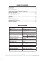
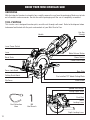
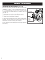
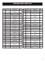
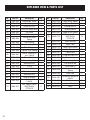
Wen 3625 4-1/2" Mini Circular Saw is a compact and powerful tool suitable for a variety of cutting tasks. With a 120V AC, 5A motor and a no-load speed of 3500 RPM, it delivers enough power to handle most cutting jobs around the house or workshop. It features a 4-1/2" blade with a 3/8" arbor size, capable of cutting depths of up to 1-11/16" at 90 degrees and 1-1/8" at 45 degrees. The saw also includes a laser guide for increased accuracy, a dust tube to keep your work area clean, and a comfortable grip for extended use.
Wen 3625 4-1/2" Mini Circular Saw is a compact and powerful tool suitable for a variety of cutting tasks. With a 120V AC, 5A motor and a no-load speed of 3500 RPM, it delivers enough power to handle most cutting jobs around the house or workshop. It features a 4-1/2" blade with a 3/8" arbor size, capable of cutting depths of up to 1-11/16" at 90 degrees and 1-1/8" at 45 degrees. The saw also includes a laser guide for increased accuracy, a dust tube to keep your work area clean, and a comfortable grip for extended use.


-
 1
1
-
 2
2
-
 3
3
-
 4
4
-
 5
5
-
 6
6
-
 7
7
-
 8
8
-
 9
9
-
 10
10
-
 11
11
-
 12
12
-
 13
13
-
 14
14
-
 15
15
-
 16
16
-
 17
17
-
 18
18
-
 19
19
-
 20
20
-
 21
21
-
 22
22


Wen 3625 4-1/2" Mini Circular Saw is a compact and powerful tool suitable for a variety of cutting tasks. With a 120V AC, 5A motor and a no-load speed of 3500 RPM, it delivers enough power to handle most cutting jobs around the house or workshop. It features a 4-1/2" blade with a 3/8" arbor size, capable of cutting depths of up to 1-11/16" at 90 degrees and 1-1/8" at 45 degrees. The saw also includes a laser guide for increased accuracy, a dust tube to keep your work area clean, and a comfortable grip for extended use.
Ask a question and I''ll find the answer in the document
Finding information in a document is now easier with AI