
Do not return unit to store
If you have any questions or concerns when
installing, operating or maintaining your
water purifier, call our toll free number:
1-800-693-1138
or visit www.ecopure.com
When you call, please be prepared to provide
the model number and date code of your
product, found on the rating decal, located
inside the cover.
Manufactured and warranted by
Ecodyne Water Systems
1890 Woodlane Drive
Woodbury, MN 55125
How to install, operate
and maintain your
Water Purifier
Model ECOP40
Installation and Operation Manual
201-8404273 (Rev. 01 7/27/17)
System tested and certified by NSF International
against NSF/ANSI Standards 42 and 53 for the
performance claims listed on pages 12 and 13.
The ECOP40 system is certified by
NSF International against NSF Protocol P231
for Microbiological Water Purifiers, based on
the recommmendations set forth in the
U.S. EPA Guide Standard and Protocol for
Testing Microbiological Water Purifiers
(OPP Task Force Report, 1987).

2
TABLE OF CONTENTS
Page
What the Water Purifier will Do . . . . . . . . . . . . . . . . . . . . . . . . . . . . . . . . . . . . . . . . . . . . . . . . . . . . . . . . . . . . . . . . . 3
Before You Start . . . . . . . . . . . . . . . . . . . . . . . . . . . . . . . . . . . . . . . . . . . . . . . . . . . . . . . . . . . . . . . . . . . . . . . . . . . . 3
S
pecifications & Dimensions . . . . . . . . . . . . . . . . . . . . . . . . . . . . . . . . . . . . . . . . . . . . . . . . . . . . . . . . . . . . . . . . . . . 3
Parts of the System . . . . . . . . . . . . . . . . . . . . . . . . . . . . . . . . . . . . . . . . . . . . . . . . . . . . . . . . . . . . . . . . . . . . . . . . . . 4
Materials & Tools Needed . . . . . . . . . . . . . . . . . . . . . . . . . . . . . . . . . . . . . . . . . . . . . . . . . . . . . . . . . . . . . . . . . . . . . 4
Typical Undersink Installation . . . . . . . . . . . . . . . . . . . . . . . . . . . . . . . . . . . . . . . . . . . . . . . . . . . . . . . . . . . . . . . . . . 4
Installation Instructions . . . . . . . . . . . . . . . . . . . . . . . . . . . . . . . . . . . . . . . . . . . . . . . . . . . . . . . . . . . . . . . . . . . . . . 5-7
Step A - Install Supply Water Fitting . . . . . . . . . . . . . . . . . . . . . . . . . . . . . . . . . . . . . . . . . . . . . . . . . . . . . . . . . . 5
Step B - Make Hole for Filtered Water Faucet . . . . . . . . . . . . . . . . . . . . . . . . . . . . . . . . . . . . . . . . . . . . . . . . . . 6
Step C - Install Faucet . . . . . . . . . . . . . . . . . . . . . . . . . . . . . . . . . . . . . . . . . . . . . . . . . . . . . . . . . . . . . . . . . . . . 6
Step D - Make Tubing Connections . . . . . . . . . . . . . . . . . . . . . . . . . . . . . . . . . . . . . . . . . . . . . . . . . . . . . . . . . . 7
Step E - Turn On Water, Check for Leaks and Rinse Carbon Fines . . . . . . . . . . . . . . . . . . . . . . . . . . . . . . . . . 7
Filter Cartridges . . . . . . . . . . . . . . . . . . . . . . . . . . . . . . . . . . . . . . . . . . . . . . . . . . . . . . . . . . . . . . . . . . . . . . . . . . . . . 8
Filter Cartridge Life . . . . . . . . . . . . . . . . . . . . . . . . . . . . . . . . . . . . . . . . . . . . . . . . . . . . . . . . . . . . . . . . . . . . . . . 8
Filter Cartridge Replacement . . . . . . . . . . . . . . . . . . . . . . . . . . . . . . . . . . . . . . . . . . . . . . . . . . . . . . . . . . . . . . . 8
Faucet Electronics & Battery Change . . . . . . . . . . . . . . . . . . . . . . . . . . . . . . . . . . . . . . . . . . . . . . . . . . . . . . . . . . . . 9
Troubleshooting the System . . . . . . . . . . . . . . . . . . . . . . . . . . . . . . . . . . . . . . . . . . . . . . . . . . . . . . . . . . . . . . . . . . . 9
Exploded View & Parts List . . . . . . . . . . . . . . . . . . . . . . . . . . . . . . . . . . . . . . . . . . . . . . . . . . . . . . . . . . . . . . . . 10-11
Performance Data . . . . . . . . . . . . . . . . . . . . . . . . . . . . . . . . . . . . . . . . . . . . . . . . . . . . . . . . . . . . . . . . . . . . . . . 12-13
WARRANTY
ONE YEAR LIMITED WARRANTY ON WATER PURIFIER
(except filter cartridges)
Warrantor: Ecodyne Water Systems, 1890 Woodlane Drive, Woodbury, MN 55125
Warrantor guarantees, to the original owner, that the Water Purifier, when installed and maintained in accordance with the
instructions, will be free from defects in materials and workmanship for a period of one (1) year from the date of purchase.
If, within the first year, a part proves, after inspection, to be defective, Warrantor will, at its sole option, either replace or
repair the part without charge except normal shipping and installation charges. Labor to maintain the equipment is not part
of the warranty. Filters, which are expendable, are not covered by the warranty.
TO OBTAIN WARRANTY PARTS, SIMPLY CALL 1-800-693-1138 for assistance. This warranty applies only while this
product is in use in the United States or Canada.
General Provisions
The above warranties are effective provided the Water Purifier is operated at water pressures not exceeding 100 psi, and
at water temperatures not exceeding 100°F; provided further that the Water Purifier is not subject to abuse, misuse, alter-
ation, neglect, freezing, accident or negligence; and provided further that the Water Purifier is not damaged as the result of
any unusual force of nature such as, but not limited to, flood, hurricane, tornado or earthquake.
Warrantor is excused if failure to perform its warranty obligations is the result of strikes, government regulation, materials
shortages, or other circumstances beyond its control.
*THERE ARE NO WARRANTIES ON THE WATER PURIFIER BEYOND THOSE SPECIFICALLY DESCRIBED ABOVE.
ALL IMPLIED WARRANTIES, INCLUDING ANY IMPLIED WARRANTY OF MERCHANTABILITY OR OF FITNESS FOR
A PARTICULAR PURPOSE, ARE DISCLAIMED TO THE EXTENT THEY MIGHT EXTEND BEYOND THE ABOVE PERI-
ODS. THE SOLE OBLIGATION OF WARRANTOR UNDER THESE WARRANTIES IS TO REPLACE OR REPAIR THE
COMPONENT OR PART WHICH PROVES TO BE DEFECTIVE WITHIN THE SPECIFIED TIME PERIOD, AND WAR-
RANTOR IS NOT LIABLE FOR CONSEQUENTIAL OR INCIDENTAL DAMAGES. NO WARRANTOR DEALER, AGENT,
REPRESENTATIVE, OR OTHER PERSON IS AUTHORIZED TO EXTEND OR EXPAND THE WARRANTIES EXPRESS-
LY DESCRIBED ABOVE.
Some states do not allow limitations on how long an implied warranty lasts or exclusions or limitations of incidental or con-
sequential damage, so the limitations and exclusions in this warranty may not apply to you. This warranty gives you spe-
cific legal rights, and you may have other rights which vary from state to state. This warranty applies to consumer-owned
installations only.

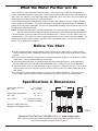
16"
3-1/2"12-3/4"
3
Before You Start
Specifications & Dimensions
16”
3-1/2”12-3/4”
q Read all steps and guides carefully before installing and using your water purifier. Follow all steps
exactly to correctly install. Reading this manual will also help you to get all the benefits from the water
purifier.
q Do not use for the treatment of water that is visually contaminated (cloudy) or has an obvious contami-
nation source, such as contamination by raw sewage.
q All plumbing should be done in accordance with local codes and requirements. In Massachusetts,
plumbing code 248 CMR 3.00 and 10.00 shall be adhered to. Consult with your licensed plumber.
q The water purifier works on water pressures of 30 psi (minimum) to 100 psi (maximum). If your house
water pressure is over the maximum, install a pressure reducing valve in the water supply pipe to the
filter system.
q Do not install the water purifier outside, or in extreme hot or cold temperatures. Temperature of the
water supply to the filter system must be between 40°F and 100°F. Do not install on hot water.
What the Water Purifier will Do
T
he ECOP40 is a water purification treatment system. This system uses a triple filter configuration to
remove undesirable elements in your water. These elements may include chlorine taste and odor, particu-
l
ates, lead, virus, bacteria, cysts, and many organic compounds. At the same time, the system allows the
minerals found in water to remain, for great tasting water.
The ECOP40 utilizes patented technology to ensure a safe water supply for the user. Replace all filters
e
very 6 months or 550 gallons. The purifier technology is designed to stop flowing when its capability to
protect the user has been exhausted. This one-of-a-kind failsafe technology ensures that the user will not
be exposed to contaminated water.
NOTE: A performance data sheet is included listing what the system will reduce from the water supply.
See the performance data sheet for individual contaminants and microbial reduction performance.
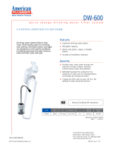
The drinking water system fits under the kitchen or bathroom sink. However, you can install it where it is
most convenient. You need a COLD water supply pipe within a few feet (6 feet of tubing is included). You
can purchase longer lengths of tubing if needed to reach more distant points. Be sure tubing is accept-
able for use on potable water supplies.
Supply Water Pressure . . . . . . . . . . 30 - 100 psi
Min. - Max. (207 - 689 kPa)
Supply Water Temperature . . . . . . . 40 - 100 °F
Min. - Max. (4 - 38 °C)
Inlet - Outlet . . . . . . . 3/8” quick connect fittings
and tubing included
Maximum Supply Water Iron,
Manganese & Hydrogen Sulfide . . . . . . . . . . . 0
FIG. 1
Questions? Call Toll Free 1-800-693-1138 or visit www.ecopure.com
When you call, please be prepared to provide the model, date code and serial number,
found on the rating decal located inside the cover.

4
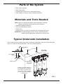
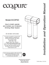
Parts of the System
Filtered Water
Faucet
SINK
Water Supply
Fitting
HOT
COLD
Shutoff Valve
Yellow Tubing
WATER IN
Blue Tubing
WATER OUT
Install the mounting hardware at
least
15-1/2” above the bottom
of the cabinet, to provide a mini-
mum of 1-1/2" under the system
for removing the filter cartridges
to change them.
8-1/2”
Filter
1
Filter
2
Filter
3
FIG. 2
= F
ilter system assembly
= Water supply fitting
= F
iltered water faucet for sink or countertop mounting
= C
olor coded 3/8" tubing to make all needed connections
Materials and Tools Needed
NOTE: Gather the required tools before starting installation. Read and
follow the instructions provided with any tools listed here.
= Slotted and Phillips screwdrivers
= Pliers and adjustable jaw wrench
= Tubing cutter
= Electric drill and 1-1/4" drill bit if mounting hole is needed for the faucet
IMPORTANT: To avoid damaging the sink, consult a qualified plumber or
installer for drilling procedures in porcelain or stainless steel.
Typical Undersink Installation
Plan to install the water filtration system near the cold water supply pipe, under the kitchen and/or bath-
room sink, to filter the cold drinking water. Refer to the following drawing.

5
Installation Instructions
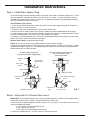
Step A - Install Water Supply Fitting
Step B - Make Hole For Filtered Water Faucet
IMPORTANT: To avoid damaging the sink, consult a qualified plumber or installer for drilling procedures
in porcelain, stainless steel or granite. Special drill bits are made for this.
1. Select one of the following places to install the faucet. Be sure there is room underneath so you can
make the needed connections.
= In an existing sink spray attachment hole.
= Drill a hole in the sink top.
= Drill a hole in the countertop next to the sink.
2. If drilling is needed make a 1-1/4" dia. (minimum) hole for the faucet.
A. Water supply connection
(using included water supply fitting)
B. Water supply typical connection
(using compression fitting)
- parts not provided -
cold water shutoff
3/8" compression fitting
insert
ferrule
cold water
pipe
3/8" tubing to
water filter inlet
cold water shutoff
cold water
shutoff
3/8" tubing to
water filter inlet
cold water
line
water supply
fitting
FIG. 3
Check and comply with local plumbing codes as you plan, then install a cold water supply fitting. The fit-
ting must provide a leak-tight connection to the water filter 3/8" tubing. A typical connection using the
included water supply fitting is shown in Figure 3A. An optional connection using standard plumbing fit-
tings (not included) is shown in Figure 3B.
Included Water Supply Fitting
1. Close the cold water shutoff valve (angle stop valve) that the water supply fitting will be installed on,
and open faucet(s) to relieve pressure.
2. Disconnect the existing cold water line from the water shutoff valve.
3. Make sure that the water supply fitting’s gasket is inside the female threaded portion of the fitting.
4. Install the water supply fitting onto the cold water shutoff valve, where the existing cold water line was
removed, and hand tighten. Be careful not to cross thread or overtighten.
5. Connect the existing cold water line to the male threaded portion of the water supply fitting and hand
tighten. Be careful not to cross thread or overtighten.
Optional Pipe Fittings (compression type shown)
NOTE: Be sure to turn off the water supply and open a faucet to drain the pipe.
Complying with plumbing codes, install a fitting on the cold water pipe to adapt 3/8" OD tubing. A typical
connection is shown in Figure 3B. If threaded fittings are used, be sure to use pipe joint compound or
thread sealing tape on outside threads.
gasket

6
Installation Instructions
faucet base
1/4 turn to connect
faucet to base
screw
toggle bolt
rubber washer
hole in sink
or countertop
faucet
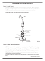
Step C - Install Faucet
1. Feed the 3/8" tubing that is attached to the faucet through the mounting hole. Slide the toggle bolts
t
hrough the mounting hole. Tighten the screws to secure the base flat on the mounting surface. Do not
overtighten.
2. Move the faucet down onto the base. Turn 1/4 clockwise to attach the faucet to the base.
3. Install battery in base. See “Battery Change” section for instructions.
FIG. 4
Step D - Make Tubing Connections
NOTE: Remove protective foam plugs before connecting tubes (See Fig. 5). Discard foam plugs.
1. Allowing some slack, measure and cut a length of 3/8" tubing to connect between the supply fitting
and the filter system inlet (See Figure 2). Cut the ends of the tubing square.
2. Insert tubing all the way into the supply fitting and inlet fitting. Pull on the tubing to be sure that it's
held firmly in the fittings.
3. Repeat steps 1 and 2 to connect tubing from the faucet to the filter system outlet (See Figure 2).
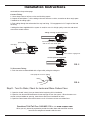
Tubing Connection (all push-in fitting locations):
This system includes push-in fittings for quick tubing connections. If working with the fittings, do the fol-
lowing.
continued on the next page

7
Installation Instructions
To Disconnect Tubing:
1. Push the collet inward and hold with a finger while pulling the tubing out.
tubing
collet (depress to remove tubing)
end of tubing round and smooth,
with no cuts, nicks or flat spots
correct full 3/4" engagement
Tubing correctly cut and connected
Incorrect partial engagement
Remove and discard foam plugs
foam plug
push in fitting
c
ontinued from the previous page
Connect Tubing:
1
. Use a sharp cutter or knife to cut the end of tubing square.
2
. Inspect the end (about 1") of the tubing to be sure there are no nicks, scratches or other rough spots.
If needed cut the tubing again.
3. Push tubing through the collet and all the way into fitting. Full engagement is 3/4" length of tube into
the fitting.
If tubing other than supplied with the system is used, be sure it is of high quality, exact size and round-
ness with a smooth surface.
FIG. 5
FIG. 6
Step E - Turn On Water, Check for Leaks and Rinse Carbon Fines
1. Open the shutoff valve(s) that you closed at the beginning of this installation.
2. Open the sink faucet and filtered water faucet to purge air from the system. When the water runs
smooth, with no bubbles or spurting, close faucets and check installation for leaks.
3. Open the filtered water faucet and let water run for 10 minutes to rinse out carbon fines.
Questions? Call Toll Free 1-800-693-1138 or visit www.ecopure.com
When you call, please be prepared to provide the model, date code and serial number,
found on the rating decal located inside the cover.

8
Register for reminders to change filters
at www.ecopure.com
FIG. 7
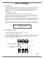
Filter Cartridges
Filter Cartridge Life
Taste and Odor, and Purifying Cartridges: Taste and odor, and purifying cartridges contain activated
c
arbon. When new, open the filtered water faucet and allow fine, carbon particles to purge from the
cartridges. Flush for 10 minutes. It is recommended to replace filter cartridges every six months or
550 gallons of use. There are several variables that determine how long a cartridge will last.
These include:
1. How much water you use, and
2. How much sediment, taste and/or odor, or other unwanted substance, is in the water.
Use the following information as a guide. However, no matter which type of cartridge you are using, you
will know it is time to replace them when you first notice the return of the unwanted sediment, taste
and/or odor in your water, or when the flow diminishes or stops.
EcoPure Water Purifier system model ECOP40 with replacement element pack ECOWPF conforms to
NSF/ANSI 42 and 53 for the specific performance claims as verified and substantiated by test data. The
rated capacity for this system is 550 gallons (2,082 liters) at a rated service flow of 0.74 gallons per
minute.
State of Wisconsin Required Statement: Do not use in Wisconsin with water that is microbiologically
unsafe, or of unknown quality, without adequate point of entry (i.e. whole house) disinfection before this
device.
Filter Cartridge Replacement
1. Turn filter cartridge to the left to remove cartridges from the filter heads.
2. Dispose of the cartridges in a proper manner.
3. Install new cartridges. Turn cartridges to the right to re-attach to the filter heads.
Taste and Odor, and Purifying Cartridges: Taste and odor, and purifying cartridges contain activated
carbon, a black powder. When new, open the filtered water faucet and allow fine, carbon particles to
purge from the cartridges. Flush for 10 minutes.
head
filter cartridge
Turn filter cartridge to the left
to remove from head
Turn filter cartridge to the right
to attach to head
Filter
1
Filter
2
Filter
3

9
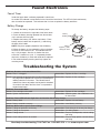
Faucet Electronics
Troubleshooting the System
Faucet Timer
Inside the faucet base is a battery operated 6 month timer.
An amber LED indicator is also located in the front of the faucet base. This LED will flash continuously
after 6 months have passed. This indicates that it is time to replace the battery and filters.
Battery Change
To change the battery, complete the following steps.
1. Loosen the screw on the right side of the faucet base.
2. Press the battery housing upwards from faucet base
until it releases from the base.
3. Replace the battery (CR 2032 or equivalent). Place
battery into the holder with the positive (+) side facing
the back of the holder.
NOTE: Recycle or properly dispose of the old battery.
4. When the battery is first replaced the light in the base
will flash six times and turn off. This indicates the bat-
tery is fully charged. After the six flashes the timer
enters the 6 month time cycle. If it repeatedly flashes
two times, the battery is weak and needs to be replaced.
5. Re-install the battery housing and firmly tighten the
mounting screw.
FIG. 8
battery
housing
screw
battery,
negative (-) side
facing the front
Problem: No water or decreased water flow.
Cause: Filter 1 is clogged. Correction: Replace the filter 1 cartridge.
Cause: Flow through the purifying filter will decrease and eventu-
ally clog when exposed to an excess of microbiological
loading materials in the water. This failsafe feature
reduces the chance of product use beyond its intended
life, and will shut down the filter when it is exposed to
contaminated water.
Correction: Replace all filter cartridges.
Problem: Taste and/or Odor.
Cause: Filter cartridges exhausted. Correction: Replace all filter cartridges.
Cause: System contaminated. Correction: Sanitize system. Call 1-800-693-1138
for instructions.
Problem: Faucet LED indicator light does not function after battery change.
Cause: Battery dead. Correction: Replace with new battery.
Cause: Battery installed incorrectly. Correction: Install battery correctly.
Problem: Water leaks at push connect fittings.
Cause: Tubing not pushed in all the way. Correction: Push tubing in all the way into fittings.
Cause: Tubing not cut square. Correction: Cut tubing square.
Cause: Tubing nicked. Correction: Remove nicked portion, reinsert tubing
into fitting.
Cause: Outer tubing surface not smooth. Correction: Remove rough portion, reinsert tubing
into fitting.
Need help troubleshooting? Call Toll Free 1-800-693-1138 or visit www.ecopure.com

10
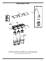
Exploded View
12
3
4
4
5
6
7
8
Questions? Call Toll Free 1-800-693-1138 or visit www.ecopure.com
When you call, please be prepared to provide the model, date code and serial number,
found on the rating decal located inside the cover.

11
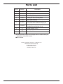
Parts List
Key No. Part No. Description
1 7292674 Faucet, Chrome, with base & electronics
2 7268382 Cover (3 req.)
3 119-8600088 Water Supply Fitting, 3/8” Q.C.
4 7168435 Tubing, 3/8” OD x 72” long, White
5 7313682 Repl. Head Assembly
6 ECOWPF
Repl. Filter Cartridges, 1 each of Sediment,
LTO (Lead, Taste & Odor) & Purifying Ù
– 7333129
Mounting Hardware Kit
(includes 2 ea. of Key Nos. 7 & 8)
7
á
Hanger Washer (2 req.)
8
á
Screw (2 req.)
¢
201-8404273 Owner’s Manual
To order repair parts call toll free 1-800-693-1138.
Manufactured and warranted by
Ecodyne Water Systems
1890 Woodlane Drive
Woodbury, MN 55125
Ù Please purchase replacement cartridges from the retailer where you
bought your water purifier system.
¢ Not illustrated.

12
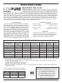
Performance Data
Model ECOP40 Water Purifier
IMPORTANT NOTICE: Read this performance data and compare the capabilities
of this unit with your actual water treatment needs. It is recommended that, before
purchasing a water treatment unit, you have your water supply tested to determine
your actual water treatment needs. This filter system is designed to be used for the reduction of the performance claims listed
b
elow. Do not use for the treatment of water that is visually contaminated (cloudy) or has an obvious contamination source,
such as contamination by raw sewage. This system is not intended to convert waste water or raw sewage into drinking water.
Systems certified for cyst reduction may be used on disinfected water that may contain filterable cysts. While testing was per-
formed under standard laboratory conditions, actual performance of this system may vary based on local water conditions.
Some or all of the contaminants reduced by this unit may not be in your water supply. See elsewhere in this owner’s manual
for further instructions on filter cartridge replacement, system installation, operating procedures, and warranty. The mainte-
nance instructions must be followed for the product to perform as indicated below.
General Information
This system conforms to NSF Protocol P231 for Microbio -
logical Water Purifiers. This filter improves the taste and
odor and reduces many chemical contaminants in drinking
water. The faucet indicator monitors the length of time the
filter has been installed and will flash amber continuously;
indicating the filters and battery need to be replaced. This
system has been tested according to NSF/ANSI 42 and 53
for reduction of the substances listed below. The concentra-
tion of the indicated substances in water entering the system
was reduced to a concentration less than or equal to the
permissible limit for water leaving the system, as specified
in NSF/ANSI 42 and 53. The testing was performed using
spiked tap water at a flow rate of 0.74 gpm (2.8 L/min.), pH
of 7.5 ± 0.5, pressure of 60 psig, and temperature of 68 ±5°F.
Installation Requirements
Pressure Range ..................... 30-100 psig (207-689 kPa)
Temperature Range ............................. 40-100°F (5-38°C)
Service Flow Rate........................... 0.74 gpm (2.8 L/min.)
Service Life.............................. 550 Gallons (2,082 Liters)
Maintenance
Cartridges should be replaced every 550 gallons or six
months, whichever comes first. Replacement filter prices
will vary. Current pricing of replacement filter pack
ECOWPF is approximately $70.00 to $100.00.
PERFORMANCE CLAIMS
Contaminant
NSF Required
Influent Level
(
µ
g/L)
2
NSF Max. Per -
missible Effluent
Level (
µ
g/L)
2
Average Influent
Level (
µ
g/L)
2
Avg. / Max.
Effluent
(
µ
g/L)
2
Avg. / Min.
Percent
Reduction
EPA MCL
1
(
µ
g/L)
2
Lead @ pH 6.5 150 ±10% 10 160 1.1 / 5.2 99.3 / 96.8 15
Lead @ pH 8.5 150 ±10% 10 150 1.2 / 3.5 99.2 / 97.7 15
Substance
Chlorine Taste & Odor 2,000 ±10% 50%
3
1,900 50 / 60 97.4 / 96.9 None
4
Particulate, Class I
(0.5 to <1 micron)
10,000
particles / mL
5
85%
3
6,800,000
particles / mL
5
10,200 / 18,000
particles / mL
5
99.9 / 99.6 None
4
VOC Reduction
6
Chloroform 300 ±10% 95% 330 1.9 / 11 98.0 / 96.7 15
1
Environmental Protection Agency Maximum Contaminant Level, as required under the Safe Drinking Water Act.
2
Micrograms per Liter, which is equivalent to parts per billion (PPB).
3
NSF minimum percent reduction requirement. Acceptance level for this substance is based on percent reduction, rather than
maximum effluent concentration.
4
The EPA has not determined an MCL for this chemical.
5
Particulate Class I reported in particles per milliliter.
6
Chloroform was used as a surrogate for the reduction of chemicals specified in the Organic Chemicals Reduced by Chloroform
Surrogate Testing table.
Cyst, virus and bacteria reduction tested by BioVir
Labs, in accordance with the U.S. EPA test protocol.
Substance Log Reduction % Reduction
Cyst 3.5 99.95%
Virus 4 99.99%
Bacteria 6 99.9999%
System tested and certified by NSF International
against NSF/ANSI Standards 42 and 53 for the
performance claims listed on pages 12 and 13.
The ECOP40 system is certified by
NSF International against NSF Protocol P231
for Microbiological Water Purifiers, based on
the recommmendations set forth in the
U.S. EPA Guide Standard and Protocol for
Testing Microbiological Water Purifiers
(OPP Task Force Report, 1987).

13
Performance Data
1
Influent challenge levels are average influent concentrations determined in surrogate qualification testing.
2
Environmental Protection Agency Maximum Contaminant Level, as required under the Safe Drinking Water Act.
3
Micrograms per Liter, which is equivalent to parts per billion (PPB).
4
Maximum product water level was not observed, but was set at the detection limit of analysis.
5
Maximum product water level is set at a value determined in surrogate qualification testing.
6
Chemical reduction percent and maximum product water level calculated at chloroform 95% breakthrough point, as determined in sur-
rogate qualification testing.
7
The surrogate test results for Heptachlor Epoxide demonstrated a 98% reduction. These data were used to calculate an upper occur-
rence concentration, which would produce a maximum product water level at the MCL.
Contaminant
Avg.
1
Influent
(µg/L)
3
Maximum
Effluent
(µg/L)
3
Percent
Removal
EPA
MCL
2
(µg/L
)
3
Alachlor 50 1.0
4
>98 2.0
Atrazine 100 3.0
4
>97 3.0
Benzene 81 1.0
4
99 5.0
Carbofuran 190 1.0
4
>99 40
Carbon Tetrachloride 78 1.8
5
98 5.0
Chlorobenzene 77 1.0
4
99 100
Chloropicrin 15 0.2
5
99 NA
2,4-D 110 1.7
5
98 70
Dibromochloropropane
(DBCP)
52 0.02
4
>99 0.2
o-Dichlorobenzene 80 1.0
4
99 600
p-Dichlorobenzene 40 1.0
4
98 75
1,2-Dichloroethane 88 4.8
6
95
6
5.0
1,1-Dichloroethylene 83 1.0
4
99 7.0
cis-1,2-Dichloroethylene
170 0.5
4
>99 70
trans-1,2-Dichloroethylene
86 1.0
4
99 100
1-2-Dichloropropane 80 1.0
4
99 5.0
cis-1,3-Dichloropropylene
79 1.0
4
99 NA
Dinosorb 170 0.2
5
99 7.0
Endrin 53 0.59
5
99 2.0
Ethylbenzene 88 1.0
4
99 700
Ethylene Dibromide (EDB)
44 0.02
4
>99 0.05
Haloacetonitriles (HAN):
NA
Bromochloroacetonitrile
22 0.5
5
98 NA
Dibromoacetonitrile 24 0.6
5
98 NA
Dichloroacetonitrile 9.6 0.2
5
98 NA
Trichloroacetonitrile 15 0.3
5
98 NA
Contaminant
Avg.
1
Influent
(µg/L)
3
Maximum
Effluent
(µg/L)
3
Percent
Removal
EPA
MCL
2
(µg/L
)
3
Haloketones (HK): NA
1,1-Dichloro-2-Propanone 7.2 0.1
5
99 NA
1,1,1-Trichloro-2-Propanone 8.2
6
0.3
5
96 NA
Heptachlor 25 0.01
4
>99 0.4
H
eptachlor Epoxide 10.7
7
0
.2
7
9
8 0.2
Hexachlorobutadiene 44 1.0
4
98 NA
Hexachlorocyclopentadinene 60 0.002
4
>99 50
Lindane 55 0.01
4
>99 0.2
Methoxychlor 50 0.1
4
>99 40
Pentachlorophenol 96 1.0
4
99 1.0
Simazine 120 4.0
4
97 4.0
Styrene 150 0.5
4
>99 100
1,1,2,2-Tetrachloroethane 81 1.0
4
99 NA
Tetrachloroethylene 81 1.0
4
99 5.0
Toluene 78 1.0
4
99 1,000
2,4,5-TP (silvex) 270 1.6
4
99 50
Tribromoacetic acid 42 1.0
4
98 NA
1,2,4-Trichlorobenzene 160 0.5
4
>99 70
1,1,1-Trichloroethane 84 4.6
5
95 200
1,1,2-Trichloroethane 150 0.5
4
>99 5.0
Trichloroethylene 180 1.0
4
>99 5.0
Trihalomethanes (includes): 300 15 95 80
Chloroform (surrogate chemical)
Bromoform
Bromodichloromethane
Chlorodibromomethane
Xylenes (total) 70 1.0
4
99
10,000
ORGANIC CHEMICALS REDUCED BY CHLOROFORM SURROGATE TESTING
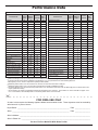
FOR IOWA USE ONLY
All sales in Iowa require the following signature before consummation of sale. These signatures must be retained by
seller/renter for 2 years minimum.
Buyer/Renter __________________________________________________________ Date _________________
Seller ________________________________________________________________ Date _________________
Seller’s Address _______________________________________________________________________________
Seller’s Phone No. _____________________________________________________________________________
Product: EcoPure Model ECOP40 Water Purifier
– – – – – – – – – – – – – – – – – – – – – – – – –
"
-
 1
1
-
 2
2
-
 3
3
-
 4
4
-
 5
5
-
 6
6
-
 7
7
-
 8
8
-
 9
9
-
 10
10
-
 11
11
-
 12
12
-
 13
13


Ask a question and I''ll find the answer in the document
Finding information in a document is now easier with AI
Related papers


Other documents
-
Watts 0958245 Installation guide
-
 American Plumber AMERICAN-PLUMBER-600R Operating instructions
-
 Eco Pure ECOP20 Specification
-
Whirlpool WHEURF User manual
-
3M 3US-PS01H Installation guide
-
No Brand RO300, 110-120 V User manual
-
Whirlpool WHEMBF5 User manual
-
-
Electrolux WE 2000 E User manual
-
unknown RO300 User manual

