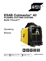
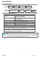
ESAB Cutmaster® 40 Plasma Cutting System SL60 1TORCH™ User manual
- Category
- Welding System
- Type
- User manual
This manual is also suitable for

Art # A-12777_AA
40
230V
120V
esab.com.br
Révision : AB Issue Date: July 31, 2015 Manual No.: 0-5376
Operating
Manual
ESAB Cutmaster
®
40
PLASMA CUTTING SYSTEM
SL60 1Torch™

WE APPRECIATE YOUR BUSINESS!
Congratulations on your new ESAB product. We are proud to have you as our customer and will strive to
provide you with the best service and reliability in the industry. This product is backed by our extensive
warranty and world-wide service network. To locate your nearest distributor or service agency, visit us on
the web at www.esab.com.br.
This Operating Manual has been designed to instruct you on the correct use and operation of your ESAB
product. Your satisfaction with this product and its safe operation is our ultimate concern. Therefore please
take the time to read the entire manual, especially the Safety Precautions. They will help you to avoid potential
hazards that may exist when working with this product.
YOU ARE IN GOOD COMPANY!
The Brand of Choice for Contractors and Fabricators Worldwide.
ESAB is a Global Brand of manual and automation Plasma Cutting Products.
We distinguish ourselves from our competition through market-leading, dependable products that have stood
the test of time. We pride ourselves on technical innovation, competitive prices, excellent delivery, superior
customer service and technical support, together with excellence in sales and marketing expertise.
Above all, we are committed to developing technologically advanced products to achieve a safer working
environment within the welding industry.

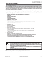
!
WARNING
Read and understand this entire Manual and your employer’s safety practices before install-
ing, operating, or servicing the equipment.
While the information contained in this Manual represents the Manufacturer's best judgement,
the Manufacturer assumes no liability for its use.
Plasma Cutting Power Supply
ESAB Cutmaster 40
SL60 1Torch™
Operating Manual Number 0-5376
Published by:
ESAB Group Inc.
2800 Airport Road
Denton, TX 76207 U.S.A.
www.esab.com.br
Copyright 2015 by ESAB
All rights reserved.
Reproduction of this work, in whole or in part, without written permission of the
publisher is prohibited.
The publisher does not assume and hereby disclaims any liability to any party for
any loss or damage caused by any error or omission in this Manual, whether such
error results from negligence, accident, or any other cause.
Original Publication Date: January 15, 2015
Revision Date: July 31, 2015
Record the following information for Warranty purposes:
Where Purchased:_______________________________ __________
Purchase Date:__________________________________ __________
Power Supply Serial #:___________________________ __________
Torch Serial #:___________________________________ __________
i

Be sure this information reaches the operator.
You can get extra copies through your supplier.
CAUTION
These INSTRUCTIONS are for experienced operators. If you are not fully familiar
with the principles of operation and safe practices for arc welding and cutting equip-
ment, we urge you to read our booklet, “Precautions and Safe Practices for Arc
Welding, Cutting, and Gouging,” Form 52-529. Do NOT permit untrained persons to
install, operate, or maintain this equipment. Do NOT attempt to install or operate this
equipment until you have read and fully understand these instructions. If you do not
fully understand these instructions, contact your supplier for further information. Be
sure to read the Safety Precautions before installing or operating this equipment.
USER RESPONSIBILITY
This equipment will perform in conformity with the description thereof contained in this manual and accompanying
labels and/or inserts when installed, operated, maintained and repaired in accordance with the instructions provided.
This equipment must be checked periodically. Malfunctioning or poorly maintained equipment should not be used.
Parts that are broken, missing, worn, distorted or contaminated should be replaced immediately. Should such repair or
replacement become necessary, the manufacturer recommends that a telephone or written request for service advice
be made to the Authorized Distributor from whom it was purchased.
This equipment or any of its parts should not be altered without the prior written approval of the manufacturer. The
user of this equipment shall have the sole responsibility for any malfunction which results from improper use, faulty
maintenance, damage, improper repair or alteration by anyone other than the manufacturer or a service facility desig-
nated by the manufacturer.
!
READ AND UNDERSTAND THE INSTRUCTION MANUAL BEFORE INSTALLING OR
OPERATING.
PROTECT YOURSELF AND OTHERS!

TABLE OF CONTENTS
SECTION 1: SAFETY..........................................................................................................................................1-1
1.0 Safety Precautions ..........................................................................................................1-1
SECTION 2 SYSTEM: INTRODUCTION ..............................................................................................................2-1
2.01 How To Use This Manual .................................................................................................2-1
2.02 Equipment Identification .................................................................................................. 2-1
2.03 Receipt Of Equipment ......................................................................................................2-1
2.04 Working Principle ............................................................................................................2-2
2.05 Power Supply Specifications ...........................................................................................2-2
2.06 Input Wiring Specifications ..............................................................................................2-3
2.07 Power Supply Features ....................................................................................................2-4
SECTION 2 TORCH: INTRODUCTION ...............................................................................................................2T-1
2T.01 Scope of Manual ........................................................................................................... 2T-1
2T.02 Specifications .............................................................................................................. 2T-1
2T.03 Introduction to Plasma .................................................................................................. 2T-2
SECTION 3: INSTALLATION ...............................................................................................................................3-1
3.01 Unpacking ....................................................................................................................... 3-1
3.02 Lifting Options ................................................................................................................. 3-1
3.03 Primary Input Power Connections .................................................................................... 3-1
3.04 Air Supply Connections ...................................................................................................3-2
SECTION 4 SYSTEM: OPERATION ....................................................................................................................4-1
4.01 Control Panel ...................................................................................................................4-1
4.02 Preparations For Operating .............................................................................................. 4-2
4.03 Sequence of Operation .................................................................................................... 4-5
4.04 Cut Quality ......................................................................................................................4-7
4.05 General Cutting Information .............................................................................................4-7
SECTION 5 SYSTEM: SERVICE ..........................................................................................................................5-1
5.01 General Maintenance ......................................................................................................5-1
5.02 Basic Troubleshooting Guide ............................................................................................5-2
SECTION 5 TORCH:
SERVICE .......................................................................................................................... 5T-1
5T.01 General Maintenance .................................................................................................... 5T-1
5T.02 Inspection and Replacement of Consumable Torch Parts ............................................... 5T-1
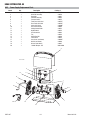
SECTION 6: PARTS LISTS .................................................................................................................................6-1
6.01 Introduction .....................................................................................................................6-1
6.02 Power Supply Replacement Parts ....................................................................................6-2
6.03 SL60 Torch Consumable Parts ......................................................................................... 6-3
6.04 Optional Accessories .......................................................................................................6-4
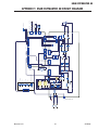
APPENDIX 1: ESAB CUTMASTER 40 CIRCUIT DIAGRAM ................................................................................ A-1
APPENDIX 2: SL60 TORCH PIN-OUT DIAGRAM ............................................................................................... A-2
Revision History .............................................................................................................................................. A-3

This Page Intentionally Blank

ESAB CUTMASTER 40
Manual 0-5376 GENERAL INFORMATION
1-1
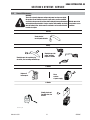
1.0 Safety Precautions
Users of ESAB welding and plasma cutting equipment have the ultimate responsibility for ensuring that anyone who works
on or near the equipment observes all the relevant safety precautions. Safety precautions must meet the requirements that
apply to this type of welding or plasma cutting equipment. The following recommendations should be observed in addition
to the standard regulations that apply to the workplace.
All work must be carried out by trained personnel well acquainted with the operation of the welding or plasma cutting
equipment. Incorrect operation of the equipment may lead to hazardous situations which can result in injury to the operator
and damage to the equipment.
1. Anyone who uses welding or plasma cutting equipment must be familiar with:
- its operation
- location of emergency stops
- its function
- relevant safety precautions
- welding and / or plasma cutting
2. The operator must ensure that:
- no unauthorized person stationed within the working area of the equipment when it is started up.
- no one is unprotected when the arc is struck.
3. The workplace must:
- be suitable for the purpose
- be free from drafts
4. Personal safety equipment:
- Always wear recommended personal safety equipment, such as safety glasses, flame proof
clothing, safety gloves.
- Do not wear loose fitting items, such as scarves, bracelets, rings, etc., which could become
trapped or cause burns.
5. General precautions:
- Make sure the return cable is connected securely.
- Work on high voltage equipment may only be carried out by a qualified electrician.
- Appropriate fire extinguishing equipment must be clearly marked and close at hand.
- Lubrication and maintenance must not be carried out on the equipment during operation.
Dispose of electronic equipment at the recycling facility!
In observance of European Directive 2002/96/EC on Waste Electrical and Electronic Equipment and its
implementation in accordance with national law, electrical and/or electronic equipment that has reached the
end of its life must be disposed of at a recycling facility.
As the person responsible for the equipment, it is your responsibility to obtain information on approved col-
lection stations.
For further information contact the nearest ESAB dealer.
ESAB can provide you with all necessary cutting protection and accessories.
SECTION 1: SAFETY

ESAB CUTMASTER 40
GENERAL INFORMATION Manual 0-5376
1-2
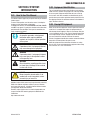
WARNING
Arc welding and cutting can be injurious to yourself and others. Take
precautions when welding and cutting. Ask for your employer's safety
practices which should be based on manufacturers' hazard data.
ELECTRIC SHOCK - Can kill.
- Install and earth (ground) the welding or plasma cutting unit in accordance with
applicable standards.
- Do not touch live electrical parts or electrodes with bare skin, wet gloves or wet clothing.
- Insulate yourself from earth and the workpiece.
- Ensure your working stance is safe.
FUMES AND GASES - Can be dangerous to health.
- Keep your head out of the fumes.
- Use ventilation, extraction at the arc, or both, to take fumes and gases away from your
breathing zone and the general area.
ARC R AYS - Can injure eyes and burn skin.
- Protect your eyes and body. Use the correct welding / plasma cutting screen and filter
lens and wear protective clothing.
- Protect bystanders with suitable screens or curtains.
FIRE HAZARD
- Sparks (spatter) can cause fire. Make sure therefore that there are no inflammable
materials nearby.
NOISE - Excessive noise can damage hearing.
- Protect your ears. Use earmuffs or other hearing protection.
- Warn bystanders of the risk.
MALFUNCTION - Call for expert assistance in the event of malfunction.
READ AND UNDERSTAND THE INSTRUCTION MANUAL BEFORE INSTALLING OR OPERATING.
PROTECT YOURSELF AND OTHERS!
WARNING
Do not use the power source for thawing frozen pipes.
CAUTION
Class A equipment is not intended for use in residential locations
where the electrical power is provided by the public low-voltage
supply system. There may be potential difficulties in ensuring
electromagnetic compatibility of class A equipment in those loca-
tions, due to conducted as well as radiated disturbances.
CAUTION
This product is solely intended for metal removal. Any other use may
result in personal injury and / or equipment damage.
CAUTION
Read and understand the instruction manual before
installing or operating.
!

ESAB CUTMASTER 40
Manual 0-5376 2-1 INTRODUCTION
SECTION 2 SYSTEM:
INTRODUCTION
2.01 How To Use This Manual
This Owner’s Manual applies to just specification or part numbers
listed on page i.
To ensure safe operation, read the entire manual, including the
chapter on safety instructions and warnings.
Throughout this manual, the words WARNING, CAUTION, DANGER,
and NOTE may appear. Pay particular attention to the information
provided under these headings. These special annotations are
easily recognized as follows:
NOTE!
An operation, procedure, or background
information which requires additional
emphasis or is helpful in efficient operation
of the system.
!
CAUTION
A procedure which, if not properly followed,
may cause damage to the equipment.
!
WARNING
A procedure which, if not properly followed,
may cause injury to the operator or others
in the operating area.
WARNING
Gives information regarding possible electri-
cal shock injury. Warnings will be enclosed
in a box such as this.
!
DANGER
Means immediate hazards which, if not
avoided, will result in immediate, serious
personal injury or loss of life.
Additional copies of this manual may be purchased by contacting
ESAB at the address and phone number in your area listed on
back cover of this manual. Include the Owner’s Manual number
and equipment identification numbers.
Electronic copies of this manual can also be downloaded at no
charge in Acrobat PDF format by going to the ESAB web site
listed below
http://www.esab.com.br
2.02 Equipment Identification
The unit’s identification number (specification or part number),
model, and serial number usually appear on a data tag attached
to the rear panel. Equipment which does not have a data tag
such as torch and cable assemblies are identified only by the
specification or part number printed on loosely attached card or
the shipping container. Record these numbers on the bottom of
page i for future reference.
2.03 Receipt Of Equipment
When you receive the equipment, check it against the invoice to
make sure it is complete and inspect the equipment for pos-
sible damage due to shipping. If there is any damage, notify the
carrier immediately to file a claim. Furnish complete information
concerning damage claims or shipping errors to the location in
your area listed in the inside back cover of this manual.
Include all equipment identification numbers as described above
along with a full description of the parts in error.
Move the equipment to the installation site before un-crating
the unit. Use care to avoid damaging the equipment when using
bars, hammers, etc., to un-crate the unit.

ESAB CUTMASTER 40
INTRODUCTION 2-2 Manual 0-5376
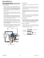
2.04 Working Principle
Rectifier
Inverter
Transformer
Rectifier
Reduce pressure, filter
Gas valve Cutting torch
Workpiece
Compressed air
Art # A-09204_AB
2.05 Power Supply Specifications
ESAB Cutmaster 40 Power Supply Specifications
Input Power 120 VAC (+
-
10%), 1 Phase, 50/60Hz
230 VAC (+
-
10%), 1 Phase, 50/60Hz
Output Current 20 Amps @ 120VAC, 15A
20-27 Amps @ 120VAC, 20A
20-40 Amps @ 230VAC, 20A
ESAB Cutmaster 40 Power Supply Duty Cycle (Note 1)
Ambient Temperature 104° F (40° C)
Duty Cycle 30% @ 120VAC, 40% @ 230VAC
Rated Current 27 Amps @ 120VAC, 40 Amps @ 230V
SL60 1Torch Gas Requirements (see section 2T.03)
Notes
1. Duty Cycle is the percentage of time the system can be operated without overheating. Duty cycle is reduced if
primary input voltage (AC) is low or the DC voltage is higher than shown in this chart.
2. Air supply must be free of oil, moisture, and other contaminants. Excessive oil and moisture may cause double-
arcing, rapid tip wear, or even complete torch failure. Contaminants may cause poor cutting performance and rapid
electrode wear. Optional filters provide increased filtering capabilities.
NOTE!
IEC Rating is determined as specified by the International Electro-Technical Commission. These specifications
include calculating an output voltage based upon power supply rated current. To facilitate comparison between
power supplies, all manufacturers use this output voltage to determine duty cycle.

ESAB CUTMASTER 40
Manual 0-5376 2-3 INTRODUCTION
Art# A-12781_AA
26lb / 11.8kg
7" (177mm)
18.5" (469.9mm)
9" (228.6mm)
120V 15A
120V 20A
230V 20A
A
24
40
20
20
30
27
Figure 2-1: Power Supply Dimensions & Weight
NOTE!
Weight includes torch & leads, input power cord, and work cable with clamp.
!
CAUTION
Provide clearance for proper air flow through the power supply. Operation without proper air flow will
inhibit proper cooling and reduce duty cycle.
2.06 Input Wiring Specifications
ESAB Cutmaster 40 Input Power Requirements
Input Power Input Current Input Current Input Suggested Sizes (See Note)
Voltage Freq. (kVA) Max (Amps) Ieff (Amps) Fuse (Amps)
(Volts-AC) (Hz) 1-Ph 1-Ph 1-Ph 1-Ph
120 50/60 3.3 27.5 15 25
230 50/60 5.0 21.4 13.5 20
Line Voltages with Suggested Circuit Protection
Motor start fuses or thermal circuit breakers are recommended for this application. Check local requirements for your situation in this
regard.
NOTE!
Refer to Local and National Codes or local authority having jurisdiction for proper wiring requirements.
Cable size is de-rated based on the Duty Cycle of the equipment.
The suggested sizes are based on flexible power cable with power plug installations.
Cable conductor temperature used is
167° F (75° C).

ESAB CUTMASTER 40
INTRODUCTION 2-4 Manual 0-5376
2.07 Power Supply Features
Air Inlet
Control Panel
To
rch Lead
120/230 VAC Power Sour
ce
Work Cable and Clamp
Art # A-12779_AA
120V 15A
120V 20A
230V 20A
A
24
40
20
20
30
27
Art# A-09335
Air Inlet
On/Off
Switch
Power Cord

Manual 0-5376 2T-1 INTRODUCTION
ESAB CUTMASTER 40
SECTION 2 TORCH:
INTRODUCTION
2T.01 Scope of Manual
This manual contains descriptions, operating instructions and main-
tenance procedures for the SL60 Plasma Cutting Torch. Service of
this equipment is restricted to properly trained personnel; unquali-
fied personnel are strictly cautioned against attempting repairs or
adjustments not covered in this manual, at the risk of voiding the
Warranty. Read this manual thoroughly. A complete understanding
of the characteristics and capabilities of this equipment will assure
the dependable operation for which it was designed.
2T.02 Specifications
A. Torch Configurations
1. Hand Torch, Model SL60
The hand torch head is at 75° to the torch handle. The hand
torches include a torch handle and torch trigger assembly.
10.125" (257 mm)
3.75"
(95 mm)
1.17" (29 mm)
Art # A-03322_AB
B. Torch Leads Lengths
Hand Torches are available as follows:
• 20 ft / 6.1 m, with ATC connectors
C. Torch Parts (see Section 6.03)
Starter Cartridge, Electrode, Tip, Shield Cup
D. Parts - In - Place (PIP)
Torch has built-in switch.
12 vdc circuit rating
E. Type Cooling
Combination of ambient air and gas stream through torch.
F. Torch Ratings
SL60 Torch Ratings
Ambient
Temperature
104° F
40° C
Duty Cycle 100% @ 60 Amps @ 400 scfh
Maximum Current 60 Amps
Voltage (V
peak
) 500V
Arc Striking Voltage
7kV
Torch Control Circuit
Voltage
24V
G. Current Ratings
SL60 Current Ratings
SL60 Torch & Leads
Up to 60 Amps, DC,
Straight Polarity
NOTE!
Power Supply characteristics will determine
material thickness range.
H. Gas Requirements
SL60 Torch Gas Specifications
Gas (Plasma and Secondary) Compressed Air
Minimum Input Pressure
60 - 95 psi
4.1 - 6.5 bar
Maximum Input Pressure 125 psi / 8.6 bar
Gas Flow
300 - 500 scfh
142 - 235 lpm
!
WARNING
This torch is not to be used with oxygen (O
2
)
This torch is not to be used with high fre-
quency starting systems.

ESAB CUTMASTER 40
INTRODUCTION 2T-2 Manual 0-5376
2T.03 Introduction to Plasma
A. Plasma Gas Flow
Plasma is a gas which has been heated to an extremely high
temperature and ionized so that it becomes electrically con-
ductive. The plasma arc cutting and gouging processes use
this plasma to transfer an electrical arc to the workpiece. The
metal to be cut or removed is melted by the heat of the arc and
then blown away.
While the goal of plasma arc cutting is separation of the material,
plasma arc gouging is used to remove metals to a controlled
depth and width.
In a Plasma Cutting Torch a cool gas enters Zone B, where a
arc between the electrode and the torch tip heats and ionizes
the gas. The main cutting arc then transfers to the workpiece
through the column of plasma gas in Zone C.
By forcing the plasma gas and electric arc through a small orifice,
the torch delivers a high concentration of heat to a small area.
The stiff, constricted plasma arc is shown in Zone C. Direct
current (DC) straight polarity is used for plasma cutting, as
shown in the illustration.
Zone A channels a secondary gas that cools the torch. This gas
also assists the high velocity plasma gas in blowing the molten
metal out of the cut allowing for a fast, slag - free cut.
A-00002
Workpiece
Power
Supply
+
_
C
B
A
Typical Torch Head Detail
B. Gas Distribution
The single gas used is internally split into plasma and second-
ary gases.
The plasma gas flows into the torch through the negative lead,
through the starter cartridge, around the electrode, and out
through the tip orifice.
The secondary gas flows down around the outside of the torch
starter cartridge, and out between the tip and shield cup around
the plasma arc.
C. Pilot Arc
When the torch is started a pilot arc is established between
the electrode and cutting tip. This pilot arc creates a path for
the main arc to transfer to the work.
D. Main Cutting Arc
DC power is also used for the main cutting arc. The negative
output is connected to the torch electrode through the torch
lead. The positive output is connected to the workpiece via
the work cable and to the torch through a pilot wire.
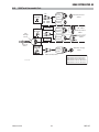
E. Parts - In - Place (PIP)
The torch includes a 'Parts - In - Place' (PIP) circuit. When the
shield cup is properly installed, it closes a switch. The torch
will not operate if this switch is open.
A-02997
Torch Trigge
r
PIP Switch
Shield Cup
To Control
Cable Wiring
Torch Switch
Parts - In - Place Circuit Diagram for Hand Torch

ESAB CUTMASTER 40
Manual 0-5376 3-1 INSTALLATION
SECTION 3: INSTALLATION
3.01 Unpacking
1. Use the packing lists to identify and account for each item.
2. Inspect each item for possible shipping damage. If damage
is evident, contact your distributor and / or shipping company
before proceeding with the installation.
3. Record Power Supply and Torch model and serial numbers,
purchase date and vendor name, in the information block at
the front of this manual.
3.02 Lifting Options
The Power Supply includes a handle for hand lifting only. Be
sure unit is lifted and transported safely and securely.
WARNING
Do not touch live electrical parts.
Disconnect input power cord before moving
unit.
!
WARNING
FALLING EQUIPMENT can cause serious
personal injury and can damage equip-
ment.
HANDLE is not for mechanical lifting.
• Only persons of adequate physical strength should
lift the unit.
• Lift unit by the handle, using two hands. Do not
use straps for lifting.
• Use optional cart or similar device of adequate
capacity to move unit.
• Place unit on a proper skid and secure in place
before transporting with a fork lift or other vehicle.
3.03 Primary Input Power Connections
Power Cords Included With Power Supply
Attached to the power supply is an input power cord with a 230
Volt 50 Amp NEMA 6-50P for plug. Optional adapters allow for
connection of the power supply input cable plug when using 120V
input power.
Art# A-09432_AB
Figure 3-1: 120VAC Adapter Pigtail
!
CAUTION
Check your power source for correct volt-
age before plugging in or connecting the
unit. The primary power source, fuse, and
any extension cords used must conform to
local electrical code and the recommended
circuit protection and wiring requirements
as specified in Section 2.
Input Volt-
age (VAC)
Rated
Output
Amps (RMS) input at
rated output, 60 Hz,
single-phase
kVA
120V, 15A
Circuit
20A, 88V
20.4 2.5
120V, 20A
Circuit
27A, 91V
28.5 3.5
120V, 30A
Circuit
27A, 91V
28.5 3.5
208-230V,
20A Circuit
40A, 96V
23-21.4 4.8

ESAB CUTMASTER 40
INSTALLATION 3-2 Manual 0-5376
3.04 Air Supply Connections
A. Connecting Air Supply to Unit
The connection is the same for compressed air or industrial compressed air in gas cylinders.
1. Connect the gas line to the compressed air inlet port at the appropriate pressure. Air inlet port is an ISO7/1 tapered fitting. A ¼
NPT adapter is included with the machine.
Art# A-09337
Air Inlet
On/Off
Switch
Figure 3-2: Gas Connection to Compressed Air input
B. Using Industrial Compressed Air In Gas Cylinders
When using Industrial compressed air in gas cylinders as the gas supply:
1. Refer to the manufacturer’s specifications for installation and maintenance procedures for high pressure gas regulators.
2. Examine the cylinder valves to be sure they are clean and free of oil, grease or any foreign material. Briefly open each cylinder
valve to blow out any dust which may be present.
3. The cylinder must be equipped with an adjustable high - pressure regulator capable of outlet pressures up to 100 psi (6.9 bar)
maximum and flows of at least 250 scfh (120 lpm).
4. Connect gas supply hose to the cylinder.
NOTE!
Pressure should be set at 100 psi (6.9 bar) at the high pressure cylinder regulator.
Supply hose must be at least 1/4 inch (6 mm) I.D.
For a secure seal, apply thread sealant to the fitting threads, according to manufacturer's instructions. Do
Not use Teflon tape as a thread sealer, as small particles of the tape may break off and block the small air
passages in the torch.

ESAB CUTMASTER 40
Manual 0-5376 4-1 OPERATION
SECTION 4 SYSTEM: OPERATION
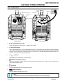
4.01 Control Panel
Art# A-12788
AC Indicator
The Front Panel The Rear Panel
Overheat Indicator
Air Indicator
DC Indicator (Ready)
Air Inlet
On/Off
Switch
Power Cord
A
120V 15A
120V 20A
230V 20A
24
40
20
20
30
27
1. ON / OFF Switch (Power Switch/Lamp)
Controls input power to the power supply. I is ON (Red Lamp), O is OFF.
2. (A) Output Current Control
Sets the desired output current. If the overload protection (fuse or circuit breaker) on the input power circuit opens frequently,
either reduce cutting output, reduce the cutting time, or connect the unit to more adequate input power. Note: For 120V input
power, the unit will automatically limit the output current to a maximum of 27A. For 230V input power, the maximum output is 40
Amps. Refer to Section 2 for input power requirements.
3. AC Indicator
Steady light indicates power supply is ready for operation.
4. OVERHEAT Indicator (TEMP Indicator)
Indicator is normally OFF. Indicator is ON when internal temperature exceeds normal limits. Allow the unit to run with the fan on
until the temp indicator turns OFF.
5. AIR Indicator
AIR light should be ON when there is sufficient gas pressure.
6. READY (DC Indicator)
Indicator is ON when DC output circuit is active.
NOTE!
All consumables must be correctly installed and maintained to ensure correct operation.

ESAB CUTMASTER 40
OPERATION 4-2 Manual 0-5376
4.02 Preparations For Operating
At the start of each operating session:
WARNING
Disconnect primary power at the source before assembling or disassembling power supply, torch parts, or
torch and leads assemblies.
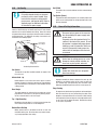
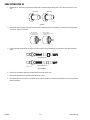
A. Torch Parts Selection
Check the torch for proper assembly and appropriate torch parts. The torch parts must correspond with the type of operation, and
with the amperage output of this power supply (60 amps maximum). Use only genuine ESAB parts with this torch.
Start
Cartridge
9-8213
Electrode
9-8215
Tips:
20A 9-8205
30A 9-8206
40A 9-8207
Tip Gouging A 9-8225 (40 Amps Max.)
Shield Cap, Gouging
9-8241
Shield Cap, Drag
40A 9-8244
40A 9-8208
Shield
Cup Body,
9-8237
40A
Shield Cap, Deflector
9-8243
Shield
Cup Body,
9-8237
Shield Cup
9-8218
Tip:
Tips:
DRAG TIP
CUTTING
40-120A
GOUGING
CUTTING
Art # A-12890
DRAG SHIELD
CUTTING
STANDOFF
CUTTING
Shield Cap, Deflector
9-8243
Shield
Cup Body,
9-8237
Shield Cup
9-8218
O-Ring No. 8-3488
Standoff Guide
9-8251
NOTE
ESAB CutMaster 60 uses 60A and less
ESAB CutMaster 80 uses 80A and less
ESAB CutMaster 100 uses 100A and less
ESAB CutMaster 120 uses 120A and less

ESAB CUTMASTER 40
Manual 0-5376 4-3 OPERATION
NOTE!
When operating the torch in a normal condition, some gas vents through the gap between the shield
cup and torch handle. Do not attempt to over tighten the shield cup as irreparable damage to internal
components may result.
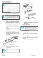
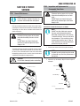
B. Torch Connection
Check that the torch is properly connected.
C. Check Primary Input Power Source
1. Check the power source for proper input voltage. Make sure the input power source meets the power requirements for the unit
per Section 2, Specifications.
2. Connect the input power cable (or close the main disconnect switch) to supply power to the system.
D. Gas Selection
Ensure gas source meets requirements listed in section 2T. Check connections and turn gas supply on.
E. Connect Work Cable
Clamp the work cable to the workpiece or cutting table. The area must be free from oil, paint and rust. Connect only to the main
part of the workpiece; do not connect to the part to be cut off.
Art # A-03387
F. Power On
Place the power supply ON / OFF switch to the ON (I) position. Power indicator turns on.
Art# A-09335
Air Inlet
On/Off
Switch
Power Cord
A
120V 15A
120V 20A
230V 20A
24
40
20
20
30
27
Art# A-09339_AD
Rear Panel with ON/OFF Switch Front Panel With Power ON/OFF Indicator

ESAB CUTMASTER 40
OPERATION 4-4 Manual 0-5376
G. Select Current Output Level
Set the desired current output level.
A
120V 15A
120V 20A
230V 20A
24
40
20
20
30
27
120V
, 15A
24
40
20
20
30
27
2
4
40
4
40
20
20
30
7
27
7
0
0
230V, 20A
24
20
27
24
20
7
27
40
20
30
A
4
30
120V, 20A
40
20
30
30
30
30
A
24
40
4
40
20
20
7
27
7
A
24
2
A
4
2
2
0
40
20
3
0
24
20
A
A
A
27
A#09697_AA
Page is loading ...
Page is loading ...
Page is loading ...
Page is loading ...
Page is loading ...
Page is loading ...
Page is loading ...
Page is loading ...
Page is loading ...
Page is loading ...
Page is loading ...
Page is loading ...
Page is loading ...
Page is loading ...
Page is loading ...
Page is loading ...
Page is loading ...
Page is loading ...
Page is loading ...
Page is loading ...
-
 1
1
-
 2
2
-
 3
3
-
 4
4
-
 5
5
-
 6
6
-
 7
7
-
 8
8
-
 9
9
-
 10
10
-
 11
11
-
 12
12
-
 13
13
-
 14
14
-
 15
15
-
 16
16
-
 17
17
-
 18
18
-
 19
19
-
 20
20
-
 21
21
-
 22
22
-
 23
23
-
 24
24
-
 25
25
-
 26
26
-
 27
27
-
 28
28
-
 29
29
-
 30
30
-
 31
31
-
 32
32
-
 33
33
-
 34
34
-
 35
35
-
 36
36
-
 37
37
-
 38
38
-
 39
39
-
 40
40


ESAB Cutmaster® 40 Plasma Cutting System SL60 1TORCH™ User manual
- Category
- Welding System
- Type
- User manual
- This manual is also suitable for
Ask a question and I''ll find the answer in the document
Finding information in a document is now easier with AI
Related papers
-
ESAB CM 39 Troubleshooting instruction
-
-
-
ESAB Powercut 700 User manual
-
-
-
-
-
ESAB CUTMASTER 40 PLASMA CUTTING SYSTEM User manual
-
Other documents
-
Lincoln Electric K2820-1 Operating instructions
-
 GIANTtech 50D User manual
-
Chicago Electric 08881 Assembly And Operating Instructions Manual
-
 Top Gun PLASMA CUT 42 PFC Manual Manual
-
 Inverter Fusion PLASMA CUT 40 User manual
-
Matco Tools MA48 User manual
-
-
 Thermal Dynamics 42 CUTMASTER Operating instructions
-
Victor Cutmaster 52 Operating instructions
-
 Thermal Dynamics 38 Cutmaster Operating instructions


