Page is loading ...

HEAVY-DUTY WOOD LATHE
MODEL G1495
INSTRUCTION MANUAL
COPYRIGHT © 1999 BY GRIZZLY INDUSTRIAL, INC.
WARNING: NO PORTION OF THIS MANUAL MAY BE REPRODUCED IN ANY SHAPE
OR FORM WITHOUT THE WRITTEN APPROVAL OF GRIZZLY INDUSTRIAL, INC.
REVISED OCTOBER, 1999. PRINTED IN U.S.A.

-2-
G1495 Heavy-Duty Wood Lathe
Table Of Contents
PAGE
1. SAFETY
SAFETY RULES FOR ALL TOOLS....................................................................................3-4
ADDITIONAL SAFETY INSTRUCTIONS FOR LATHES ......................................................5
2. CIRCUIT REQUIREMENTS
110V/220V OPERATION ......................................................................................................6
GROUNDING ........................................................................................................................6
EXTENSION CORDS............................................................................................................7
3. GENERAL INFORMATION
COMMENTARY .................................................................................................................... 8
UNPACKING..........................................................................................................................9
PIECE INVENTORY ..............................................................................................................9
CLEAN UP ..........................................................................................................................10
SITE CONSIDERATIONS....................................................................................................10
4. ASSEMBLY
PRE-ASSEMBLY..................................................................................................................11
STAND............................................................................................................................11-13
TOOL REST ........................................................................................................................13
TAILSTOCK..........................................................................................................................14
GUARD ASSEMBLY............................................................................................................14
5. ACCESSORIES
INTRODUCTION..................................................................................................................15
SANDING ATTACHMENTS ............................................................................................15-16
SPUR CENTER ..................................................................................................................16
TAILSTOCK..........................................................................................................................17
TAILSTOCK LIVE CENTER............................................................................................17-18
FACEPLATE ........................................................................................................................18
OUTBOARD TOOL REST....................................................................................................19
ACCESSORY REMOVAL ....................................................................................................19
6. OPERATIONS
INTRODUCTION..................................................................................................................20
TEST RUN ..........................................................................................................................20
TURNING TOOLS................................................................................................................21
SPEED SELECTOR ............................................................................................................22
TURNING SPEEDS ............................................................................................................22
SPINDLE TURNING ............................................................................................................23
FACEPLATE TURNING........................................................................................................24
INDEXING............................................................................................................................25
SANDING ............................................................................................................................25
7. MAINTENANCE
GENERAL............................................................................................................................26
LATHE BED ........................................................................................................................26
LUBRICATION ....................................................................................................................26
V-BELTS ..............................................................................................................................26
8. CLOSURE..................................................................................................................................27
WARRANTY AND RETURNS................................................................................................................34

G1495 Heavy-Duty Wood Lathe
-3-
Safety Instructions For Power Tools
SECTION 1: SAFETY
5. KEEP CHILDREN AND VISITORS AWAY.
All children and visitors should be kept a
safe distance from work area.
6. MAKE WORK SHOP CHILD PROOF with
padlocks, master switches, or by removing
starter keys.
7. DON’T FORCE TOOL. It will do the job
better and safer at the rate for which it was
designed.
8. USE RIGHT TOOL. Don’t force tool or
attachment to do a job for which it was not
designed.
1. KEEP GUARDS IN PLACE and in working
order.
2. REMOVE ADJUSTING KEYS AND
WRENCHES. Form habit of checking to
see that keys and adjusting wrenches are
removed from tool before turning on.
3. KEEP WORK AREA CLEAN. Cluttered
areas and benches invite accidents.
4. DON’T USE IN DANGEROUS ENVIRON-
MENT. Don’t use power tools in damp or
wet locations, or where any flammable or
noxious fumes may exist. Keep work area
well lighted.
For Your Own Safety Read Instruction
Manual Before Operating This Equipment
Indicates an imminently hazardous situation which, if not
avoided, WILL result in death or serious injury.
Indicates a potentially hazardous situation which, if not avoid-
ed, COULD
result in death or serious injury.
Indicates a potentially hazardous situation which, if not avoid-
ed, MA
Y result in minor or moderate injury. It may also be
used to alert against unsafe practices.
This symbol is used to alert the user to useful information
about proper operation of the equipment.
The purpose of safety symbols is to attract your attention to possible hazardous conditions.This
manual uses a series of symbols and signal words which are intended to convey the level of
importance of the safety messages.The progression of symbols is described below. Remember
that safety messages by themselves do not eliminate danger and are not a substitute for prop-
er accident prevention measures.
NOTICE

-4-
G1495 Heavy-Duty Wood Lathe
9. USE PROPER EXTENSION CORD. Make
sure your extension cord is in good condi-
tion. Conductor size should be in accor-
dance with the chart below. The amperage
rating should be listed on the motor or tool
nameplate.An undersized cord will cause a
drop in line voltage resulting in loss of
power and overheating.Your extension cord
must also contain a ground wire and plug
pin. Always repair or replace extension
cords if they become damaged.
Minimum Gauge for Extension Cords
10. WEAR PROPER APPAREL. Do not wear
loose clothing, gloves, neckties, rings,
bracelets, or other jewelry which may get
caught in moving parts. Non-slip footwear
is recommended.Wear protective hair cov-
ering to contain long hair.
11. ALWAYS USE SAFETY GLASSES. Also
use face or dust mask if cutting operation is
dusty. Everyday eyeglasses only have
impact resistant lenses, they are NOT safe-
ty glasses.
12. SECURE WORK. Use clamps or a vise to
hold work when practical. It’s safer than
using your hand and frees both hands to
operate tool.
LENGTH
AMP RATING 25ft 50ft 100ft
0-6 18 16 16
7-10 18 16 14
11-12 16 16 14
13-16 14 12 12
17-20 12 12 10
21-30 10 10 No
Safety Instructions For Power Tools
13. DON’T OVERREACH. Keep proper footing
and balance at all times.
14. MAINTAIN TOOLS WITH CARE. Keep
tools sharp and clean for best and safest
performance. Follow instructions for lubri-
cating and changing accessories.
15. DISCONNECT TOOLS before servicing
and changing accessories, such as blades,
bits, cutters, and the like.
16. REDUCE THE RISK OF UNINTENTION-
AL STARTING. Make sure switch is in off
position before plugging in.
17. USE RECOMMENDED ACCESSORIES.
Consult the owner’s manual for recom-
mended accessories. The use of improper
accessories may cause risk of injury.
18. CHECK DAMAGED PARTS. Before fur-
ther use of the tool, a guard or other part
that is damaged should be carefully
checked to determine that it will operate
properly and perform its intended function.
Check for alignment of moving parts, bind-
ing of moving parts, breakage of parts,
mounting, and any other conditions that
may affect its operation. A guard or other
part that is damaged should be properly
repaired or replaced.
19. NEVER LEAVE TOOL RUNNING UNAT-
TENDED.TURN POWER OFF. Don’t leave
tool until it comes to a complete stop.

G1495 Heavy-Duty Wood Lathe
-5-
Additional Safety Instructions For The Lathe
Like all power tools, there is danger asso-
ciated with the Model G1495 Heavy-Duty
Lathe. Accidents are frequently caused by
lack of familiarity or failure to pay attention.
Use this tool with respect and caution to
lessen the possibility of operator injury. If
normal safety precautions are overlooked
or ignored serious personal injury may
occur.
1. MAKE SURE ALL GUARDS are in place
and that the Lathe sits on a flat, stable sur-
face.
2. ALWAYS WEAR EYE PROTECTION or a
face shield when operating the Lathe. Use
a respirator to avoid inhaling dust. All safe-
ty equipment should be ANSI approved.
3. BEFORE STARTING THE MACHINE be
certain the workpiece has been properly
imbedded on the headstock and tailstock
centers and that there is adequate clear-
ance for the full rotation.
4. ADJUST TOOL REST to provide proper
support for the turning tool you will be
using. Test tool rest clearance by rotating
workpiece by hand before turning lathe on.
5. REMOVE INDEXING PIN before turning
lathe on.
6. SELECT THE TURNING SPEED which is
appropriate for the type of work. Allow the
lathe to gain its full speed before beginning
turning.
7. ALWAYS OBSERVE THE CONDITION of
the materials you are turning. Pay particu-
lar attention to knots, splits and other
potentially dangerous conditions.
8. NEVER OPERATE THE LATHE WITH
DAMAGED OR WORN PARTS. Maintain
your lathe in proper working condition.
Perform routine inspections and mainte-
nance promptly when called for. Put away
adjustment tools after use.
9. MAKE SURE YOUR WOOD LATHE IS
TURNED OFF, disconnected from its
power source and all moving parts have
come to a complete stop before starting
any inspection, adjustment, or mainte-
nance procedure.
10. DO NOT LEAVE LATHE RUNNING
UNATTENDED for any reason.
11. DO NOT STOP LATHE USING YOUR
HAND against the workpiece.
12. KEEP LOOSE CLOTHING ARTICLES
such as sleeves, belts or jewelry items
away from the lathe spindle.
13. WHEN FACE PLATE TURNING, use lathe
chisels on the downward spinning side of
the workpiece only.
14. REMOVE THE TOOL REST when per-
forming sanding or polishing operations on
the rotating spindle.
15. KEEP LATHE TOOLS PROPERLY
SHARPENED and hold firmly in the prop-
er position when turning.

-6-
G1495 Heavy-Duty Wood Lathe
SECTION 2: CIRCUIT REQUIREMENTS
110/220V Operation
Your G1495 machine comes pre-wired for 110V
operation. It includes a three-prong plug which
should be plugged into a grounded circuit as
shown in Figure 1. Under normal use, the motor
draws approximately 12 amps @ 110V. We rec-
ommend the lathe be plugged into a circuit pro-
tected by a 15 amp circuit breaker.
This motor can be operated at 220V, however
there is no power advantage from operating at a
higher voltage. To revise the lathe to operate on
220V it is necessary to do two things:
1. The motor must be rewired according to the
wiring diagram provided at the back of this
manual.
2. The plug at the end of the power cord
needs to be cut off and replaced with a type
similar to those pictured in Figure 2.
Under normal use, the motor draws approximate-
ly 6 amps @ 220V. We recommend the lathe be
plugged into a circuit protected by a 15 amp cir-
cuit breaker.
220V/240V
15A
NEMA L6-15
Standard
Locking
Figure 2. Two typical 220V outlet configurations.
Grounding
This equipment must be grounded. Verify
that any existing electrical outlet and circuit you
intend to plug into is actually grounded. If it is
not, it will be necessary to run a separate 12
A.W.G. copper grounding wire from the outlet
to a known ground. Under no circumstances
should the grounding pin from any three-
pronged plug be removed. Serious injury may
occur.
In the event of a malfunction or breakdown,
grounding provides a path of least resistance for
electric current to reduce the risk of electric
shock.This tool is equipped with an electric cord
having an equipment-grounding conductor which
must be properly connected to a grounding plug.
The plug must be plugged into a matching outlet
that is properly installed and grounded in accor-
dance with all local codes and ordinances.
Improper connections of the electrical-grounding
conductor can result in risk of electric shock.The
conductor with green or green and yellow striped
insulation is the electrical-grounding conductor. If
repair or replacement of the electric cord or plug
is necessary, do not connect the equipment
grounding conductor to a live terminal.
Figure 1. Typical 110V plug and outlet.

G1495 Heavy-Duty Wood Lathe
-7-
We do not recommend the use of extension cords
on 220V equipment. It is much better to arrange
the placement of your equipment and the
installed wiring to eliminate the need for exten-
sion cords. If the lathe is being operated at 110V
an extension cord is acceptable, however make
sure the cord is rated Hard Service (grade S) or
better. Refer to the chart in Section 1: Safety
Instructions to determine the minimum gauge for
the extension cord.The extension cord must also
contain a ground wire and plug pin.Always repair
or replace extension cords when they become
worn or damaged.
Extension Cords Notes
We have covered some basic electrical
requirements for the safe operation of your
Lathe. These requirements are not neces-
sarily comprehensive. You must be sure
that your particular electrical configuration
complies with local and state codes.
Ensure compliance by checking with your
local municipality or a licensed electrician.

-8-
G1495 Heavy-Duty Wood Lathe
SECTION 3: GENERAL INFORMATION
We are proud to offer the Grizzly Model G1495
Heavy-Duty Wood Lathe. The Model G1495 is
part of a growing Grizzly family of fine woodwork-
ing machinery. When used according to the
guidelines set forth in this manual, you can expect
years of trouble-free, enjoyable operation and
proof of Grizzly’s commitment to customer satis-
faction.
The Model G1495 is a cabinet-type, heavy-duty
lathe designed for the serious wood turner. It pro-
vides a 40'' distance between centers and a 14''
swing over the bed, dimensions well suited for
most turning requirements. The motor is a
3
⁄4 HP
dual voltage motor which provides seven turning
speeds from 500 to 3070 RPM. This machine
includes a spur center, a live center, a large clear
plastic protective shield, and outboard mounted
accessories including sanding disc, tilting table,
pneumatic drum sander, contour flap sander and
an adjustable tool rest for faceplate turning.
A number of optional accessories for the Model
G1495 are available through the Grizzly catalog.
These include lathe chisels, chucks, faceplates,
sanding abrasives replacements and a copy
attachment for making multiple copies of a spin-
dle.
We are also pleased to provide this manual with
the Model G1495. It was written to guide you
through assembly, review safety considerations,
and cover general operating procedures. It repre-
sents our effort to produce the best documenta-
tion possible. If you have any comments regard-
ing this manual, please write to us at the address
below:
Grizzly Industrial, Inc.
C
/O Technical Documentation
P.O. Box 2069
Bellingham, WA 98227-2069
Most importantly, we stand behind our machines.
If you have any service questions or parts
requests, please call or write us at the location
listed below.
Grizzly Industrial, Inc.
2406 Reach Road
Williamsport, PA 17701
Phone: (570) 326-3806
Fax: (800) 438-5901
E-Mail: techsupport@grizzly.com
Web Site: http://www.grizzly.com
The specifications, drawings, and photographs
illustrated in this manual represent the Model
G1495 as supplied when the manual was pre-
pared. However, owing to Grizzly’s policy of con-
tinuous improvement, changes may be made at
any time with no obligation on the part of Grizzly.
Whenever possible, though, we send manual
updates to all owners of a particular tool or
machine.Should you receive one, we urge you to
insert the new information with the old and keep
it for reference.
To operate this, or any power tool, safely
and efficiently, it is essential to become as
familiar with its characteristics as possible.
The time you invest before you begin to use
your Model G1495 will be time well spent.
DO NOT operate this machine until you are
completely familiar with the contents of this
manual. Make sure you read and under-
stand all of the safety procedures. If you do
not understand something, DO NOT operate
the machine.
Commentary

G1495 Heavy-Duty Wood Lathe
-9-
Unpacking
This machine is shipped from the manufacturer in
two carefully packed cartons. If you discover the
machine is damaged after you’ve signed for deliv-
ery, and the truck and driver are gone, you will
need to file a freight claim with the carrier. Save
the containers and all packing materials for pos-
sible inspection by the carrier or its agent.Without
the packing materials, filing a freight claim can be
difficult.
If you need assistance determining
whether you need to file a freight claim, or with
the procedure to file one, please contact our
Customer Service.
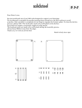
Piece Inventory
Parts should be as follows (See Figure 3):
• Stand Assembly w/ Motor Installed
• Lathe Assembly
• V-Belt
• Right Hand Stand
• Support Shelves (2)
• Floor Brackets (3)
• Shield
• Shield Support Tube
• Shield Sliding Support
• Shield Hardware Bag
Mounting Bars 2
Hex Bolts
5
⁄
16" - 18 x 4
1
⁄
2"2
Flat Washers
5
⁄16"4
• Tailstock Handle
• Sanding Attachments
Flap Sander 1
Pneumatic Drum 1
Aluminum Sanding Disc 1
Garnet Sanding Disc 1
• Arbor for Mounting Sanding Acc
• Tilting Work Table
• Work Table Support Spindle
• Outboard Tool Rest Bracket w/ 3 Bolts
• Outboard Tool Rest Support
• Outboard Tool Rest Post w/ Nut
• Faceplate
• Miter Gauge
• Tool Rest Holder
• Tool Rest
• Knockout Bar
• Allen
®
Wrench 6mm
• Hardware Bag
Hex Bolts
5
⁄16" - 18 x
3
⁄4"18
Flat Washers
5
⁄16"36
Cap Screws
5
⁄16" - 18 x 2
1
⁄2"6
Hex Nuts
5
⁄16" - 18 24
In the event that any generally used fasteners are
missing, we can replace them, or, for the sake of
expediency, replacements can be obtained at
your local hardware store.
The G1495 is a heavy machine (265 lbs.
shipping weight). DO NOT over-exert your-
self while unpacking or moving your
machine – get assistance. In the event that
your Lathe must be moved up or down a
flight of stairs, be sure that the stairs are
capable of supporting the combined weight
of people and the machine. Serious per-
sonal injury may occur.
NOTICE
A full parts list and illustrations can be
found at the back of this manual. Use this
information to identify parts or to clarify
assembly steps.
Figure 3. Parts Inventory.

-10-
G1495 Heavy-Duty Wood Lathe
Clean Up
The unpainted surfaces are coated with a waxy
oil to protect it from corrosion during shipment.
Remove this protective coating with a solvent
cleaner or citrus-based degreaser. Avoid chlo-
rine-based solvents as they may damage painted
surfaces should they come in contact. Always fol-
low the usage instructions on the product you
choose for clean up.
Many of the solvents commonly used to
clean machinery can be highly flammable,
and toxic when inhaled or ingested. Always
work in well-ventilated areas far from poten-
tial ignition sources when dealing with sol-
vents. Use care when disposing of waste
rags and towels to be sure they do not cre-
ate fire or environmental hazards. Keep
children and animals safely away when
cleaning and assembling this machine.
Do not use gasoline or other petroleum-
based solvents to remove this protective
coating.These products generally have low
flash points which makes them extremely
flammable. A risk of explosion and burning
exists if these products are used. Serious
personal injury may occur.
Site Considerations
FLOOR LOAD
Your G1495 Wood Lathe represents a fairly large
weight load in a small footprint. Most commercial
or home shop floors should be sufficient to carry
the weight of the machine. If you question the
strength of your flooring, check with a qualified
architect or building engineer to determine if rein-
forcement is required.
WORKING CLEARANCES
Working clearances can be thought of as the dis-
tances between machines and obstacles that
allow safe operation of every machine without
limitation. Consider existing and anticipated
machine needs, size of material to be processed
through each machine, and space for auxiliary
stands and/or work tables. Also consider the rel-
ative position of each machine to one another for
efficient material handling. Be sure to allow your-
self sufficient room to safely run your machines in
any foreseeable operation.
LIGHTING AND OUTLETS
Lighting should be bright enough to eliminate
shadow and prevent eye strain. Electrical circuits
should be dedicated or large enough to handle
combined motor amp loads. Outlets should be
located near each machine so power or exten-
sion cords are not obstructing high-traffic areas.
Be sure to observe local electrical codes for prop-
er installation of new lighting, outlets, or circuits.
Make your shop “child safe”. Ensure that
your workplace is inaccessible to young-
sters by closing and locking all entrances
when you are away. Never allow visitors in
your shop when assembling, adjusting or
operating equipment.
G1495 Heavy-Duty Wood Lathe
-11-
Pre-assembly
Assembly of the G1495 is straightforward. We
have organized the assembly process into steps.
Please follow them in sequence.
Tools Required: Only a few common tools are
needed to assemble this machine. Specifically,
two 12mm open end wrenches, a 6mm Allen
®
wrench (supplied), a Phillips
®
screwdriver and a
plumb bob.
SECTION 4: ASSEMBLY
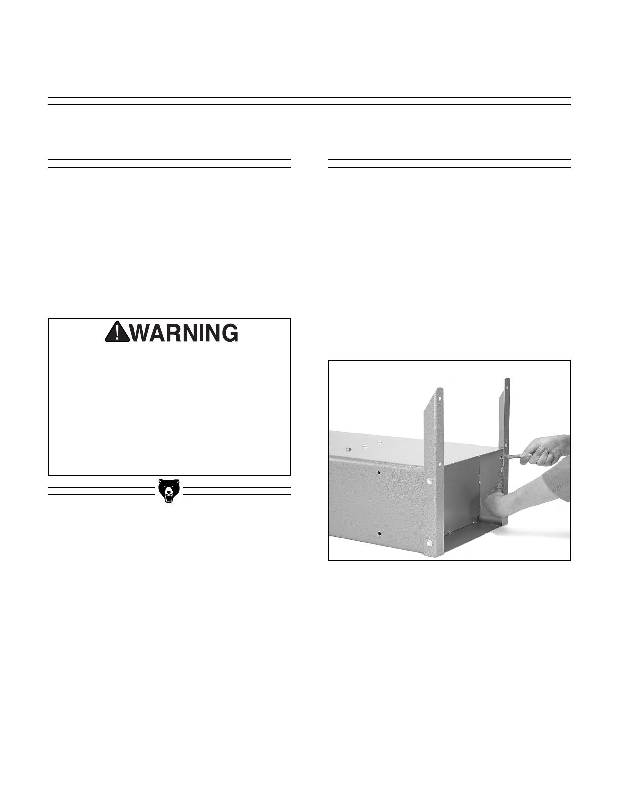
Stand
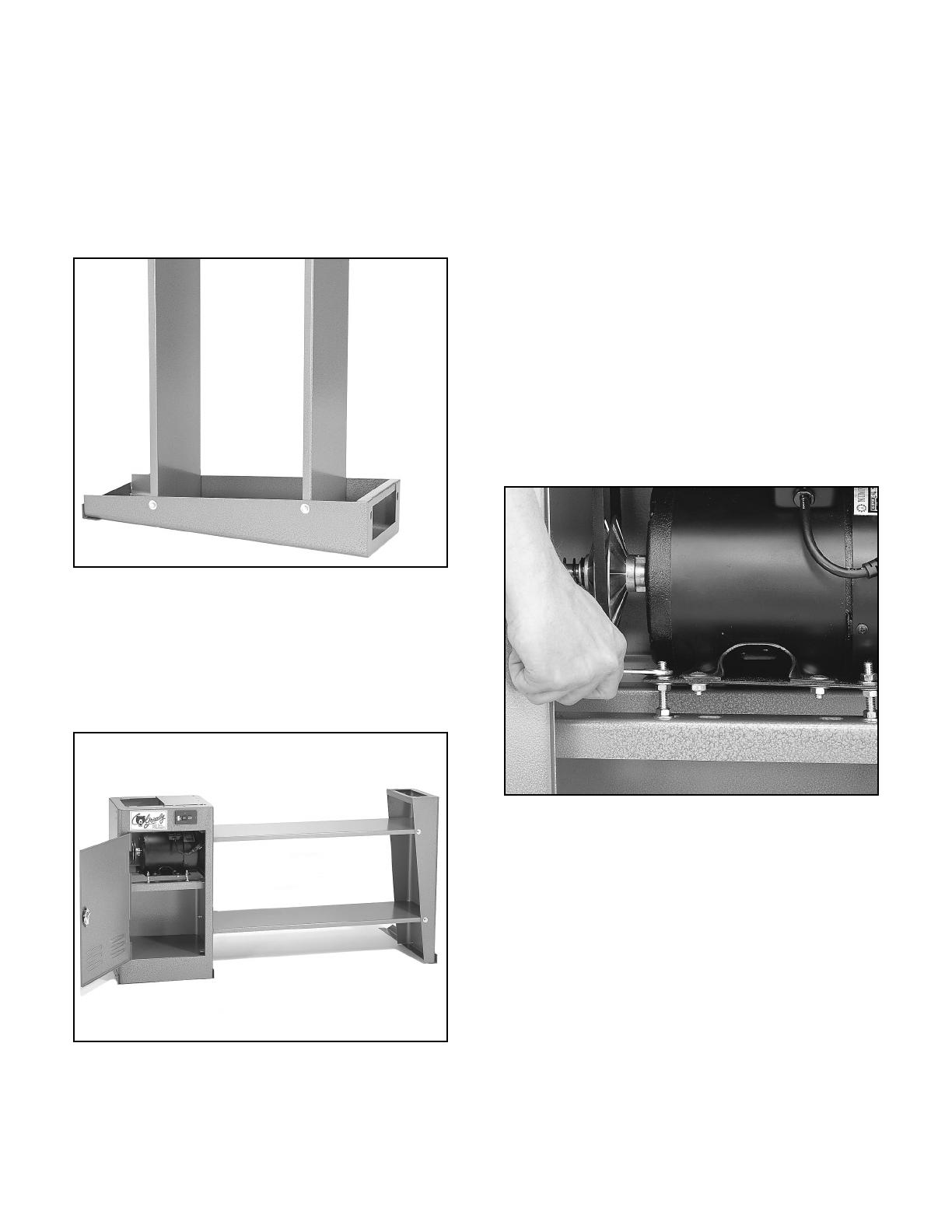
Figure 4. Attaching base brackets to stand.
(Stand is lying down on its front)
The stand components are most easily assem-
bled on their sides, then stood up and joined
together:
1. Attach the two base brackets to the base of
the cabinet using four (4)
5
⁄16'' - 18 x
3
⁄4'' bolts
and nuts.Use two (2) washers for each bolt,
one under the head of the bolt, one next to
the nut.These brackets are used when the
lathe is going to be bolted to the floor or
other type of support structure. See Figure
4.
All die-cut metal parts have a sharp edge
(called “flashing”) on them after they are
formed.This is generally removed at the fac-
tory. Sometimes a bit of flashing might
escape inspection, and the sharp edge may
cause cuts or lacerations when handled.
Please examine the edges of all die-cut
metal parts and file or sand the edge to
remove the flashing before handling.
2. Attach the third base bracket to the right
hand stand using two (2)
5
⁄16'' - 18 x
3
⁄4''
bolts, washers and nuts.
-12-
G1495 Heavy-Duty Wood Lathe
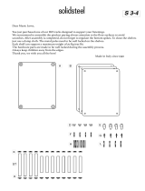
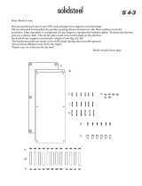
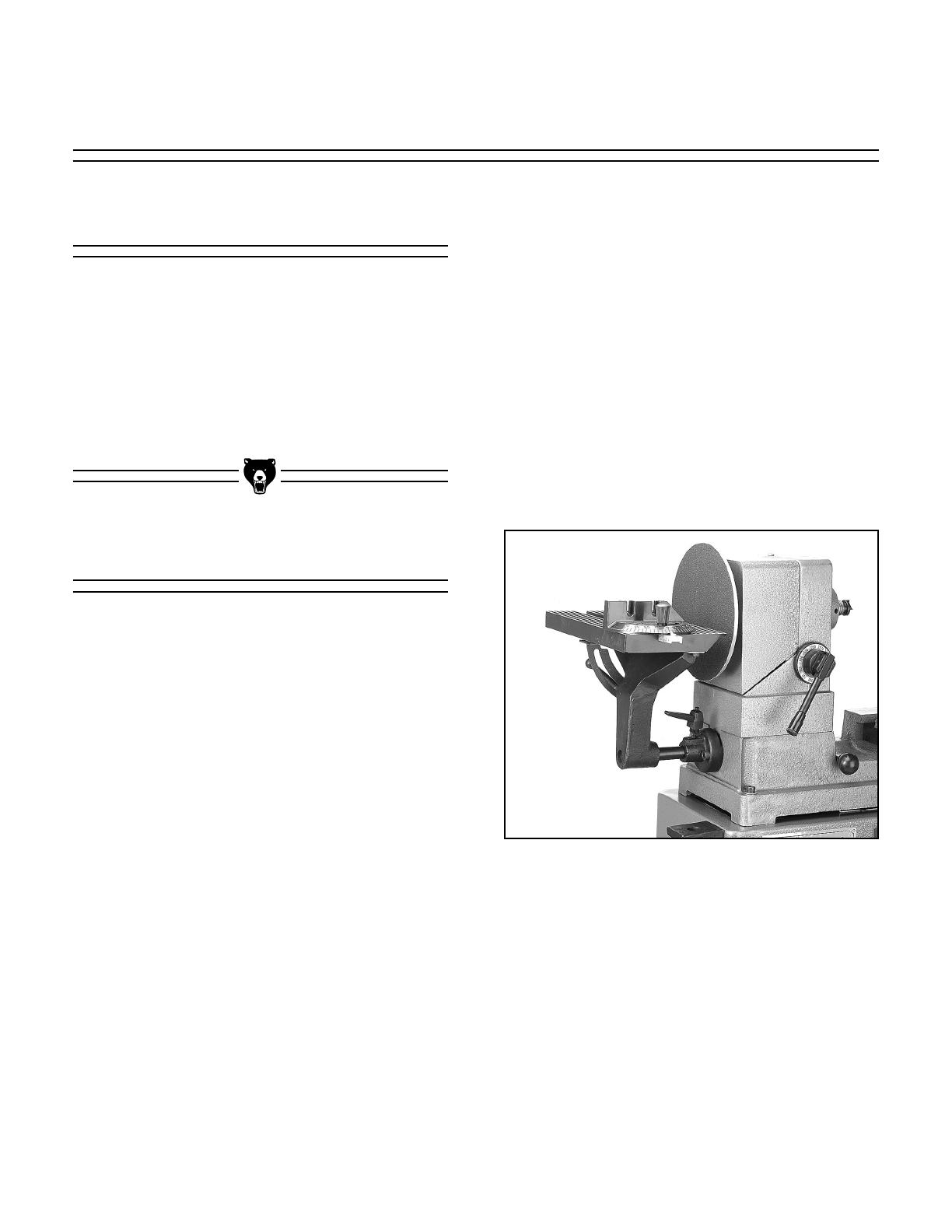
Figure 5. Attaching shelves to right hand stand.
Figure 6. Attach shelves to stand cabinet.
Figure 7. Loosening motor mount bolts.
5. With an assistant, set the lathe bed assem-
bly on the stand, with the headstock so it is
on the cabinet stand. Secure the lathe bed
to the stands using six (6)
5
⁄16'' - 18 x 2
1
⁄2''
Allen
®
head bolts, washers and nuts sup-
plied.
6. Remove the head cover from the headstock
by taking out three (3) Phillips
®
head
screws. Turn the variable speed control
lever to the highest speed position, if it is
not already there.
7. Loosen the upper hex nuts on the motor
adjustment bolts to allow the motor to pivot
upward freely. See Figure 7. Place the V-
belt over the lower pulley and lift up on the
motor while slipping the V-belt over the
upper pulley in the headstock.
3. Lay the right hand stand on its side so the
two shelves can be more easily assembled
to it. See Figure 5. The two shelves differ
by the location of the bolt holes located
along the front and rear flanges. Fasten
with four (4)
5
⁄16'' - 18 x
3
⁄4'' bolts, washers
and nuts for each shelf. Do not tighten
securely at this point.
4. Carefully position the right hand stand and
assembled shelves alongside the cabinet.
See Figure 6. Use four (4)
5
⁄16'' - 18 x
3
⁄4''
bolts, washers and nuts to secure the
upper and lower shelves to the stand.

G1495 Heavy-Duty Wood Lathe
-13-
Tool Rest
Figure 9. Mounting the tool rest.
The tool rest is equipped with a cam-action
clamping system to secure it to the lathe bed.
When the lever is thrown, a locking plate lifts up
and secures the tool rest to the bed. See Figure
9. To install the tool rest assembly:
1. Remove the large hex nut and lock plate
from the bottom of the tool rest assembly.
2. Set the tool rest assembly on the lathe bed
with the clamp stud between the bed slot.
3. Set the tool rest lock handle so it is pointing
down. Re-install the lock plate and thread
the hex nut back onto the stud until it bot-
toms out.
4. Lift the lock handle approximately 90˚ and
tighten the hex nut
1
⁄2 to
2
⁄3 of a turn more.
5. Turn the tool rest lock handle until it locks
the tool rest down onto the bed. You may
need to adjust the Hex Nut in small incre-
ments to fine tune how the tool rest assem-
bly locks down onto the bed.
Figure 8. Using plumb bob for pulley alignment.
8. To align the pulleys, set the speed control
lever mid-way between high and low so the
upper and lower pulleys are spread
approximately the same amount. Ensure
that the lathe is sitting level. Use a plumb
bob to check the side of the pulleys in rela-
tion to each other. See Figure 8.
If the pulleys are not in alignment, loosen
the motor mounting bolts and move the
motor on its mounting plate. The lathe
assembly can also be moved slightly to
achieve alignment, by loosening the bolts
installed in Step 5.
9. Tighten the motor adjusting nuts so there
is constant pressure on the V-belt from the
lower motor pulley.Ensure that the motor is
level and the pulleys are parallel with each
other. Once the V-belt is in position,
change speeds only with the motor run-
ning and the headstock cover in place. If
speed changes are necessary for adjust-
ment or testing, unplug the machine and
rotate the pulleys by hand while moving
the speed lever. Never move the speed
lever without rotating the spindle as the
belt can become jammed or the movable
pulley can be damaged.
10. At this point tighten all the bolts on the
stand. Put the headstock cover plate back
into place and secure.

G1495 Heavy-Duty Wood Lathe
G1495 Heavy-Duty Wood Lathe
Tailstock
Figure 10. Tailstock handwheel assembly.
Thread the handle onto the tailstock handwheel
and tighten down the jamnut. Figure 10.
Guard Assembly
Figure 12. Guard assembly in place.
Figure 11. Bar mounted with spacer tube.
The clear plastic guard protects the operator from
flying debris as the lathe is turning. To assemble
the guard to the machine:
1. Mount one end of the sliding bar to the back
of the lathe bed using the spacer tube, the
long bolt and washer provided. See Figure
11. Ensure that the spacer tube bevel is
against the lathe bed, positioned so the bar
will be level and parallel to the bed.
2. Before attaching the other end, slide the
tubular bracket onto the bar so the pivot
hinge faces forward.See Figure 12. Ensure
that the spacer tube bevel is against the
lathe bed, positioned so the bar will be level
and parallel to the bed.
3. Secure the other end of the bar to the back
of the lathe bed as described in Step 1.
4. Fasten the clear plastic guard to the sliding
bracket using the four (4) Phillips
®
head
screws already attached to the mounting
plate. Make sure the plastic guard is sand-
wiched between the two metal plates. For
ease of assembly, the locking knobs can be
removed which will allow the mounting
plate to be removed from the assembly.
Reinstall after attaching the clear plastic
panel.
To use, slide the guard assembly over the specif-
ic area of the stock you are turning, loosen the
lock knobs and pull the front edge of the guard
down as low as possible while still allowing
access to the workpiece.Tighten the knobs.
Bevel edge of spacer
G1495 Heavy-Duty Wood Lathe
-15-
Figure 13. Sanding disc and table.
The outboard side of the headstock spindle
accommodates a number of accessories. There
are two different sanding attachments: 1) an 8''
sanding disc and table with miter gauge, and 2) a
pneumatic drum and flap sander.
Sanding Disc and Table
1. Mount the sanding disc onto the outboard
spindle by threading it onto the
7
⁄8'' - 16 left
hand threads.The disc does not need to be
highly torqued to the spindle, the reverse
threading will cause it to self-tighten.
2. Mount the abrasive disc to the flat surface
of the aluminum disc by peeling the adhe-
sive backing off and carefully centering the
abrasive disc on the wheel.
3. Attach the sanding table in front of the
sanding disc. First install the end of the
shaft with the flat face into the bore under-
neath the table. Two setscrews tighten
against the flat land on the shaft. Loosely
tighten the setscrews for now.
Sanding Attachments
The G1495 Lathe can be used for a wide variety
of woodturning applications.There are a number
of accessories which are used for specific proce-
dures. In this section the installation and basic
operation of these accessory items is described.
In Section 6: Operations you will find more spe-
cific information about the actual turning proce-
dures and methods.
Introduction
SECTION 5: ACCESSORIES
4. Now install the other end of the shaft into
the fitting which is just below the outboard
spindle.The table is held in position with the
spring-loaded lever. Pull up on the spring
loaded shank to disengage the lever from
the adjustment screw and rotate the lever
for clearance. When the lever is in the
desired position, allow the spring to pull it
back onto the adjustment screw.
5. Position the sanding table so that the table
is approximately
1
⁄16 " away from the sanding
disc.See Figure 13. Always use the side of
the sanding disc where the downward rota-
tion will hold the piece down to the table.
G1495 Heavy-Duty Wood Lathe
G1495 Heavy-Duty Wood Lathe
Figure 14. Pneumatic drum and flap sander.
Pneumatic Drum and Flap Sander
The drum and the flap wheel attachment mount
onto the mandrel provided. See Figure 14 for
proper installation.
1. First slide the flap wheel over the end of the
mandrel and position it against the
machined land.
2. The drum sander screws onto the threaded
end of the mandrel. Remember both the
mandrel and the spindle are left-hand
threads. The drum sander should be inflat-
ed to approximately 10 PSI using a bicycle
pump or other low pressure inflation device.
Do not over-inflate.
Spur Center
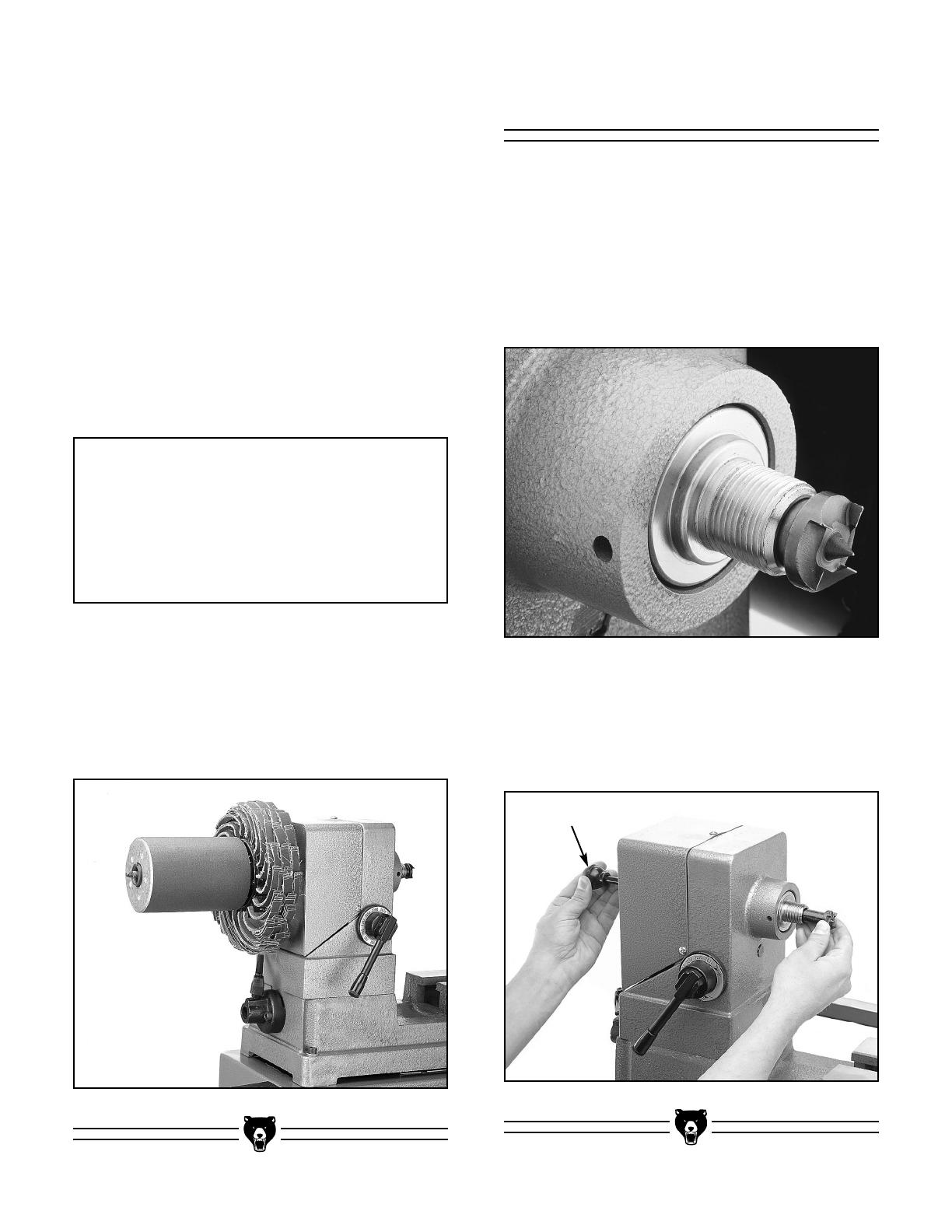
Figure 15. Spur center in headstock spindle.
The G1495 is supplied with a #2 Morse taper four
tine spur center for use when turning. The spur
center is used in conjunction with the tailstock live
center. Install the spur center by inserting into the
hole in the inboard spindle. Figure 15. See
Section 5:Operations, Spindle Turning section for
complete detail on how to properly seat the spur
center.
To remove, insert the knockout bar provided into
the outboard spindle and tap with the palm of
your hand while carefully holding onto the spur
center with your other hand. Figure 16.
Figure 16. Using knockout bar to remove center.
Knockout bar
NOTICE
Do not use a compressor to inflate the
pneumatic sanding drum, it is too easy to
over-inflate. Use a hand-operated pump
only, and check the inflation pressure with a
suitable gauge.
3. These attachments must both be mounted
on the spindle at the same time, regardless
of whether both will be used. The flap
sander attachment helps to provide rigidity
to the mandrel and drum sander when they
are installed together.
G1495 Heavy-Duty Wood Lathe
-17-
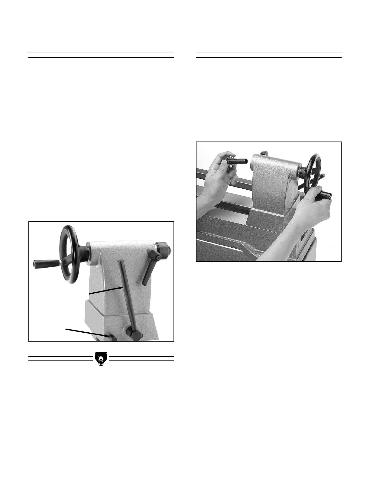
Figure 18. Tailstock spindle taper.
Tailstock
The tailstock is equipped with a cam-action
clamping system to secure it to the lathe bed.
When the lever is thrown, a locking plate lifts up
and secures the tool rest to the bed. To position
the tailstock along the bed:
1. Loosen the quick release lever and move
the tailstock to the desired position. Figure
17.
2. Re-engage the quick release lever.
3. If the quick release lever will not lock the
tailstock down onto the bed (either too
loose or too tight), loosen or tighten the hex
nut (located on the underside of the tail-
stock) in small increments as needed to
achieve the proper clamping pressure.
The tail spindle is a Morse Taper #2, the same as
the headstock. The live center is preinstalled
from the factory. To remove, turn the handwheel
counter-clockwise until the tailstock barrel bot-
toms out in the tailstock housing.This causes the
center to be forced out of the barrel. Be sure to
catch the center with your other hand as it drops
out to avoid damaging the center.See Figure 18.
Tailstock Live Center
Figure 17. Tailstock assembly.
Quick release lever
Lever Stop
Reinstall by turning the handwheel clockwise
until the tailstock barrel sticks out of the tailstock
housing about
1
⁄2''.Make certain the surface of the
taper and the inside of the tailstock bore are
clean and free of dirt. Insert the live center into
the tailstock barrel with a light amount of force to
seat the taper in the bore.When the workpiece is
secured on the centers, the force will seat the
taper more completely.
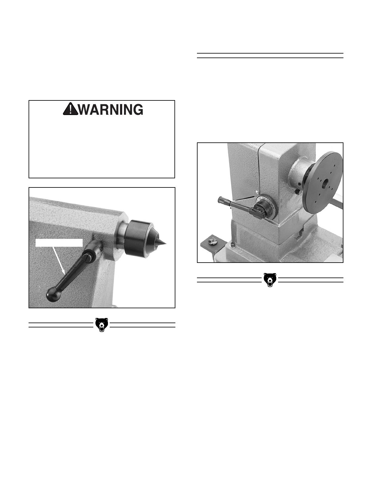
When installing the workpiece between the cen-
ters, first move the tailstock to get a rough posi-
tioning. Lock the tailstock in position with the
quick-release lever. Then using the handwheel,
crank the center firmly into the workpiece until it
is firmly seated.Lock it into position with the lock-
ing lever See Figure 19.
-18-
G1495 Heavy-Duty Wood Lathe
Face Plate
Figure 20. Face plate installed on spindle.
The G1495 is supplied with a 6'' face plate.The
faceplate is used for bowl and plate turning.
Install the face plate by threading the face plate
onto the inboard spindle.Use the knockout bar to
hold the spindle from rotating while tightening or
removing the face plate. Figure 20. Mount your
workpiece to the face plate using the mounting
holes which are bored through the face plate.
(1) The tailstock barrel lock handle must
always be locked down while the lathe is in
use. The workpiece can be thrown from the
lathe if this step is not observed. (2) The tail-
stock barrel should not protrude from the
tailstock housing more than 2''.Serious per-
sonal injury may occur.
Figure 19. Locking lever on tailstock spindle.
A drill chuck (not supplied) can also be installed
in the tailstock arbor as long as it is a Morse
Taper #2 mounting. A chuck is useful if you wish
to do boring where the workpiece is held in the
chuck and a drill bit is placed in the tailstock. In
this application the tailstock handwheel would be
used to advance the piece into the stationary drill
bit.
Locking Lever

G1495 Heavy-Duty Wood Lathe
-19-
Figure 21. Outboard tool rest.
Figure 22. Knockout bar for removal.
Outboard Tool Rest Accessory Removal
The outboard side of the headstock can be used
for faceplate turning when the diameter of the
stock exceeds what can be handled on the
inboard side.The range of diameters suitable for
outboard turning is from 14'' to a maximum of
19''. Outboard turning will require an accessory
faceplate which is available from Grizzly.
Outboard turning should always be done with the
tool rest installed:
1. Fasten the L-shaped bracket to the cabinet
stand with the two (2)
5
⁄16'' - 18 x 1'' bolts
provided and tighten with a 12mm wrench.
2. Attach the tool rest support to the bracket
with the
3
⁄4'' - 10 x 2
1
⁄2'' bolt and nut as
shown in Figure 21 This is hand-tightened
only to allow movement.
3. Insert the threaded end of the tool rest post
into the cast boss and secure with the
3
⁄4''
hex nut.This also is only hand-tightened.
4. The tool rest can now be placed into the
end of the support post and secured with
the setscrew.
To remove accessories such as faceplates, sand-
ing discs or the drum/flap sander from the head-
stock spindle, insert the knockout bar into the
hole in the headstock near the inboard spindle.
Turn the spindle by hand until the bar engages
one of the indexing holes, which will lock the spin-
dle in position. While holding the knockout bar,
rotate the accessory counterclockwise if mounted
inboard, or counterclockwise if mounted on the
outboard side. See Figure 22.

-20-
G1495 Heavy-Duty Wood Lathe
SECTION 6: OPERATIONS
Test Run
Once the assembly is complete and all fasteners
and accessories have been tightened securely,
you are ready to test the machine.Do not attempt
to mount any workpiece on the spindle for this ini-
tial test run. Connect the machine to the main
power supply. Press the START button. Make
sure that your finger is poised on the STOP but-
ton, just in case there’s a problem. The Wood
Lathe should run smoothly, with little or no vibra-
tion or rubbing noises. Strange or unnatural nois-
es should be investigated and corrected before
operating the machine further. Vibrations or rat-
tling noises will most commonly come from a tool
rest or tailstock which has not been locked down
into position.
If the lathe runs smoothly, try mounting a piece of
turning stock (See Spindle Turning heading for
instructions on how to mount). If a problem per-
sists, stop the machine and review all the assem-
bly steps and adjustments. Call for assistance, if
needed.
Introduction
This section describes some of the basic infor-
mation required to use your G1495 Heavy Duty
Wood Lathe. It concentrates on methods of
mounting the workpiece to the machine for the
various operations.We do not go into great detail
about specific turning procedures here because
there are a wide variety of tools and methods to
achieve the needs of a particular project.
We recommend you consult one of the many fine
reference books on woodturning and lathe opera-
tion for more detail as you build your skills with
the lathe. Many communities also have wood-
working associations or adult education programs
which are an excellent way to learn turning tech-
niques firsthand.
DO NOT attempt to investigate or adjust the
machine while it is running. Wait until the
machine is turned off, unplugged and all
working parts have come to a rest before
you do anything! Serious personal injury
may occur.
Like all power tools, there is danger associ-
ated with the Model G1495 Heavy-Duty
Wood Lathe. Accidents are frequently
caused by lack of familiarity or failure to pay
attention. Use this tool with respect and
caution to lessen the possibility of operator
injury. If normal safety precautions are over-
looked or ignored, serious personal injury
may occur.
/