Page is loading ...


Operation Manual
Xs Series Power Amplifiers
page 2

page 3
Xs Series Power Amplifiers
Operation Manual
DECLARATION of CONFORMITY
Crown International, Inc.
Sue Whitfield
574-294-8289
European Representative's Name and Address:
Nick Owen
19 Clos Nant Coslech
Pontprennau
Cardiff
CF23 8ND United Kingdom
Equipment Type: Commercial Audio Power Amplifiers
Family Name: Xs
Model Names: Xs4300, Xs1200, Xs900, Xs700, Xs500
EMC Standards:
EN 55103-1:1995 Electromagnetic Compatibility - Product Family Standard for Audio, Video, Audio-Visual and Entertainment Lighting Control Apparatus for Professional Use, Part 1: Emissions
EN 55103-1:1995 Magnetic Field Emissions-Annex A @ 10 cm and 1 M
EN 61000-3-2:1995+A14:2000 Limits for Harmonic Current Emissions (equipment input current ≤16A per phase)
EN 61000-3-3:1995 Limitation of Voltage Fluctuations and Flicker in Low-Voltage Supply Systems Rated Current ≤16A
EN 55022:1992 + A1: 1995 & A2:1997 Limits and Methods of Measurement of Radio Disturbance Characteristics of ITE: Radiated, Class B Limits; Conducted, Class B
EN 55103-2:1996 Electromagnetic Compatibility - Product Family Standard for Audio, Video, Audio-Visual and Entertainment Lighting Control Apparatus for Professional Use, Part 2: Immunity
EN 61000-4-2:1995 Electrostatic Discharge Immunity (Environment E2-Criteria B, 4k V Contact, 8k V Air Discharge)
EN 61000-4-3:1996 Radiated, Radio-Frequency, Electromagnetic Immunity (Environment E2, criteria A)
EN 61000-4-4:1995 Electrical Fast Transient/Burst Immunity (Criteria B)
EN 61000-4-5:1995 Surge Immunity (Criteria B)
EN 61000-4-6:1996 Immunity to Conducted Disturbances Induced by Radio-Frequency Fields (Criteria A)
EN 61000-4-11:1994 Voltage Dips, Short Interruptions and Voltage Variation
Safety Standard:
EN 60065: 1998 Safety Requirements - Audio Video and Similar Electronic Apparatus
I certify that the product identified above conforms to the requirements of the EMC Council Directive 89/336/EEC as amended by 92/31/EEC, and the Low Voltage Directive 73/23/EES as amended by 93/68/EEC.
Larry Coburn
Signed
Title: Senior Vice President of Manufacturing
Date of Issue: March 1, 2003
Issued By: Crown International, Inc.
1718 W. Mishawaka Road
Elkhart, Indiana 46517 U.S.A.
Due to line current harmonics, we recommend that you contact your supply authority before connection.

Operation Manual
Xs Series Power Amplifiers
page 4
Important Safety Instructions ...........................................................2
Declaration of Conformity ................................................................3
1 Welcome .......................................................5
1.1 Features ...............................................................................5
1.2 How to Use This Manual ......................................................5
2 Setup ............................................................ 6
2.1 Unpack Your Amplifier ........................................................6
2.2 Install Your Amplifier ..........................................................6
2.3 Ensure Proper Cooling .......................................................6
2.4 Choose Input Wire and Connectors ....................................7
2.5 Choose Output Wire and Connectors ..................................7
2.6 Wire Your System ...............................................................8
2.6.1 Stereo Mode ..............................................................8
2.6.2 How to Parallel the Inputs...........................................8
2.6.3 Bridge-Mono Mode ...................................................9
2.7 Connect to AC Mains...........................................................10
2.8 Protecting Your Speakers ....................................................10
2.9 Startup Procedure............................................................ ...10
3 Operation ....................................................... 11
3.1 Precautions...........................................................................11
3.2 Front Panel Controls and Indicators..................................... 12
3.3 Back Panel Controls and Connectors (2-channel models).....13
3.4 Back Panel Controls and Connectors (Xs4300).....................14
4 Advanced Features and Options............................. 15
4.1 Protection Systems ...............................................................15
4.1.1 Output Current Limiting ...............................................15
4.1.2 DC Protection ..............................................................15
4.1.3 Circuit Breaker .............................................................15
4.1.4 Thermal Protection ......................................................15
5 Troubleshooting ............................................... 16
6 Specifications ................................................. 17
7 AC Power Draw and Thermal Dissipation.................. 19
8 Service . ....................................................... 22
8.1 Worldwide Service .................................................................22
8.2 US and Canada Service..........................................................22
8.2.1 Service at a US or Canada Service Center ...................22
8.2.2 Factory Service ............................................................22
8.2.3 Factory Service Shipping Instructions .........................22
9 Warranty ....................................................... 23
Crown Factory Service Information Form..........................................27
Table of Contents

page 5
Xs Series Power Amplifiers
Operation Manual
Xs500
2-ohm Dual (per ch.) 750W**
4-ohm Dual (per ch.) 500W
8-ohm Dual (per ch.) 400W
4-ohm Bridge
8-ohm Bridge
1 kHz
Power*
*1 kHz Power: refers to maximum average power
in watts at 1kHz with 0.15% THD.
1,450W
1,600W**
** at 0.5% THD.
Xs700
2-ohm Dual (per ch.) 900W**
4-ohm Dual (per ch.) 750W
8-ohm Dual (per ch.) 450W
4-ohm Bridge
8-ohm Bridge
1 kHz
Power*
*1 kHz Power: refers to maximum average power
in watts at 1kHz with 0.15% THD.
1,645W
1,900W**
** at 0.5% THD.
1 Welcome
The Xs Series of power amplifiers from Crown
®
represents a new era in affordable, quality
power amplification. The line consists of five
models: four 2-channel units and one 4-chan-
nel unit, each in a uniform, rugged chassis. The
Xs Series incorporates the best of tried-and-
true design principles and innovative features.
Modern power amplifiers are sophisticated
pieces of engineering capable of producing
extremely high power levels. They must be
treated with respect and correctly installed if
they are to provide the many years of reliable
service for which they were designed.
In addition, Xs Series amplifiers include a
number of features which require some expla-
nation before they can be used to their maxi-
mum advantage.
Please take the time to study this manual so
that you can obtain the best possible service
from your amplifier.
1.1 Features
• Housed in a rugged, all-steel 2U chassis.
• Efficient forced-air fans prevent excessive
thermal buildup.
• 2-channel models have touch-proof binding
post outputs, Speakon
®
outputs, Phoenix-style
inputs, and electronically balanced XLR-1/4"
combo inputs with daisy-chain XLR outputs.
Xs4300 has XLR-1/4" combo inputs and
touch-proof binding post outputs.
• Features precision detented level controls,
power switch, and eight LEDs which indicate
signal and clip for each channel, AC mains,
power, bridge mode, temperature and fault con-
ditions.
• Microprocessor-controlled protection sys-
tem.
• Three-Year, No-Fault, Fully Transferable
Warranty completely protects your investment
and guarantees its specifications.
1.2 How to Use This Manual
This manual provides you with the necessary
information to safely and correctly setup and
operate your amplifier. It does not cover every
aspect of installation, setup or operation that
might occur under every condition. For addi-
tional information, please consult Crown’s
Amplifier Application Guide (available online at
www.crownaudio.com), Crown Technical Sup-
port, your system installer or retailer.
We strongly recommend you read all instruc-
tions, warnings and cautions contained in this
manual. Also, for your protection, please send
in your warranty registration card today. And
save your bill of sale — it’s your official proof
of purchase.
Xs900
2-ohm Dual (per ch.)
4-ohm Dual (per ch.)
900W
8-ohm Dual (per ch.) 600W
4-ohm Bridge
8-ohm Bridge
1 kHz
Power*
*1 kHz Power: refers to maximum average power
in watts at 1kHz with 0.15% THD.
2,100W
2,500W**
** at 0.5% THD.
1,200W**
Xs4300
4-ohm Dual (per ch.)
300W
8-ohm Dual (per ch.) 200W
8-ohm Bridge
1 kHz
Power*
*1 kHz Power: refers to maximum average power
in watts at 1kHz with 0.15% THD.
700W
Xs1200
2-ohm Dual (per ch.)
4-ohm Dual (per ch.)
8-ohm Dual (per ch.)
4-ohm Bridge
8-ohm Bridge
1 kHz
Power*
*1 kHz Power: refers to maximum average power
in watts at 1kHz with 0.15% THD.
2,300W
3,000W**
** at 0.5% THD.
1,600W**
650W
1,100W

Operation Manual
Xs Series Power Amplifiers
page 6

page 7
Xs Series Power Amplifiers
Operation Manual
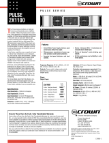
2.4 Choose Input Wire
and Connectors
Crown recommends using pre-built or professionally wired bal-
anced line (two-conductor plus shield), 22-24 gauge cables and
connectors. At the amplifier inputs, use either:
• 3-pin male XLR cable ends,
• TRS or TS 1/4" phone plugs, or
• Phoenix-style connectors (2-channel models only).
Unbalanced lines may be used, but may result in noise over long
cable runs.
Figure 2.3
Combo Input Connector XLR
Wiring, Balanced (Top) and
Unbalanced (Bottom)
Figure 2.5
Phoenix-Style Input Connector Wiring,
Balanced (Top) and Unbalanced (Bottom).
Note Jumper Between “S” and “–”
2 Setup
Figure 2.3 shows XLR wiring, Figure 2.4 shows 1/4" phone plug
wiring, and Figure 2.5 shows Phoenix-style connector wiring.
NOTE: Custom wiring should only be performed by qual-
ified personnel.
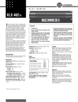
2.5 Choose Output Wire and Connectors
Crown recommends using pre-built or professionally wired, high-
quality, two- or four-conductor, heavy gauge speaker wire and
connectors. You can use banana plugs, spade lugs, or bare wire
for your output connectors (Figure 2.6). Also, in the 2-channel
models, you can use a 4-pole Speakon
®
connector (Figure 2.7
and Table 1). To prevent the possibility of short-circuits, wrap or
otherwise insulate exposed loudspeaker cable connectors.
Note: Binding post outputs on European models come
with safety plugs installed to prevent European power-
cord plugs from being inserted. The top & bottom entry
positions for these connectors should therefore be used
with European models.
Using the guidelines below, select the appropriate size of wire
based on the distance from amplifier to speaker.
Distance Wire Size
up to 25 ft. 16 AWG
26-40 ft. 14 AWG
41-60 ft. 12 AWG
61-100 ft. 10 AWG
101-150 ft. 8 AWG
151-250 ft. 6 AWG
CAUTION: Never use shielded cable for output wiring.
Figure 2.6
Binding Post Output Wiring for 2-Channel Models

Operation Manual
Xs Series Power Amplifiers
page 8

page 9
Xs Series Power Amplifiers
Operation Manual

Operation Manual
Xs Series Power Amplifiers
page 10
NOTE: In Bridge-Mono mode, only the
Channel 1 Level control is functional.
2.7 Connect to AC Mains
Connect your amplifier to the AC mains power
source (power outlet) with the supplied AC power
cordset. First, connect the IEC end of the cordset to
the IEC connector on the amplifier; then, plug the
other end of the cordset to the AC mains. The AC
Mains indication light on the front panel should be
lit.
WARNING: The third prong of this connector
(ground) is an important safety feature. Do
not attempt to disable this ground connec-
tion by using an adapter or other methods.
Amplifiers don’t create energy. The AC mains volt-
age and current must be sufficient to deliver the
power you expect. You must operate your amplifier
from an AC mains power source with not more than
a 10% variation above or a 15% variation below the
amplifier’s specified line voltage and within the
specfied frequency requirements (indicated on the
amplifier’s back panel label). If you are unsure of the
output voltage of your AC mains, please consult
your electrician.
2.8 Protecting Your Speakers
It’s wise to avoid clipping the amplifier signal. Not
only does clipping sound bad, it can damage high-
frequency drivers. To prevent clipping, insert a lim-
iter between your mixer output and amplifier input.
That way, no matter how strong a signal your mixer
produces, the amplifier will not clip. Set the limiter
threshold so that mixer signals above 0 on the
mixer meters do not quite drive the amplifier into
clipping.
Also, avoid sending strong subsonic signals to the
amplifier. High-level, low-frequency signals from
breath pops or dropped microphones can blow out
drivers. To prevent subsonic signals, insert a high-
pass filter between mixer output and amplifier input
(or between mixer and limiter). Alternatively, switch
in highpass filters at your mixer. Set the filter to as
high a frequency as possible that does not affect
your program. For example, try 35 Hz for music and
75 Hz for speech. On each mixer input channel, set
the filter frequency just below the lowest fundamen-
tal frequency of that channel's instrument.
2.9 Startup Procedure
Use the following procedure when first turning on
your amplifier:
1. Turn down the level of your audio source.
2. Turn down the level controls of the amplifier.
3. Turn on the “Power” switch. The Power indica-
tor should glow.
4. Turn up the level of your audio source to an
optimum level.
5. Turn up the Level controls on the amplifier until
the desired loudness or power level is
achieved. NOTE: In Bridge-Mono mode, only
the Channel 1 Level control is functional.
6. Turn down the level of your audio source to its
normal range.
If you ever need to make any wiring or installation
changes, don’t forget to disconnect the power cord.
For help with determining your system’s optimum
gain structure (signal levels) please refer to the
Crown Amplifier Application Guide, available online
at www.crownaudio.com.
2 Setup

page 11
Xs Series Power Amplifiers
Operation Manual
3.1 Precautions
Your amplifier is protected from internal and exter-
nal faults, but you should still take the following
precautions for optimum performance and safety:
1. Before use, your amplifier first must be config-
ured for proper operation, including input and
output wiring hookup. Improper wiring can
result in serious operating difficulties. For
information on wiring and configuration, please
consult the Setup section of this manual or, for
advanced setup techniques, consult Crown’s
Amplifier Application Guide available online at
www.crownaudio.com.
2. Use care when making connections, selecting
signal sources and controlling the output level.
The load you save may be your own!
3. Do not short the ground lead of an output cable
to the input signal ground. This may form a
ground loop and cause oscillations.
4. WARNING: Never connect the output to
a power supply, battery or power main.
Electrical shock may result.
3 Operation
5. Tampering with the circuitry, or making unau-
thorized circuit changes may be hazardous and
invalidates all agency listings.
6. Do not operate the amplifier with the red Clip
LEDs constantly flashing.
7. Do not overdrive the mixer, which will cause
clipped signal to be sent to the amplifier. Such
signals will be reproduced with extreme accu-
racy, and loudspeaker damage may result.
8. Do not operate the amplifier with less than the
rated load impedance. Due to the amplifier’s
output protection, such a configuration may
result in premature clipping and speaker dam-
age. Operating the Xs4300 with a 2-ohm
load is not recommended, as the ampli-
fier might shut down. The Xs500, 700
900 and 1200 can be used with a 2-ohm
load.
Remember: Crown is not liable for damage that
results from overdriving other system compo-
nents.

Operation Manual
Xs Series Power Amplifiers
page 12

page 13
Xs Series Power Amplifiers
Operation Manual

Operation Manual
Xs Series Power Amplifiers
page 14
3.4 Back Panel Controls and
Connectors (Xs4300)
A. Normal/Bridge Switch
(one per channel pair)
Two-position switch selects between normal
(stereo) operation and Bridge-Mono operation.
B. Circuit Breaker
Provides overload protection.
C. XLR-1/4" Combo Input Connectors
One per channel, XLR-1/4" combo connector
includes 3-pin female XLR connector and
TRS 1/4" phone jack. Accepts balanced or
unbalanced signals.
D. 5-Way Binding Post Output
Connectors
One pair per channel; accept banana plugs,
spade lugs or bare wire.
Note: Binding post outputs on European mod-
els come with safety plugs installed to prevent
European power-cord plugs from being
inserted. The top & bottom entry positions for
these connectors should therefore be used with
European models.
E. IEC Power Inlet
3 Operation

page 15
Xs Series Power Amplifiers
Operation Manual
4 Advanced Features
and Options
NOTE: For detailed information about
these Crown amplifier features, please
consult the Crown Amplifier Application
Guide, available on the Crown website
at www.crownaudio.com.
4.1 Protection Systems
Your Crown amplifier provides extensive pro-
tection and diagnostic capabilities, including
output current limiting, microprocessor-con-
trolled DC protection, circuit breaker, and spe-
cial thermal protection for the unit’s
transformers.
4.1.1 Output Current Limiting
Output Current Limiting circuitry protects the
amplifier output stage from damage caused by
short-circuit loads.
4.1.2 DC Protection
DC Protection disconnects the loudspeaker
load in the event of an output DC offset exceed-
ing 2V. In such an event the yellow Fault LED
will illuminate (see Figure 4.1) and the ampli-
fier channel will be muted. In the majority of
cases, DC protection is indicative of a faulty
amplifier channel, and will be accompanied by
an illuminated Clip LED, even with no input
connected and level controls set at minimum. If
this is the case, contact your dealer or service
center.
4.1.3 Circuit Breaker
The high-voltage power supplies of your Crown
amplifier are protected by a circuit breaker. The
breaker rating varies depending on model and
supply voltage as follows:
4.1.4 Thermal Protection
The Thermal Protection circuit will activate if
the internal heatsink temperature exceeds
proper operating temperatures (194 °F, 90 °C).
When the heatsink temperature has fallen to a
safe level, this protection circuit will automati-
cally be reset. Principle causes of thermal pro-
tection are:
1) Inadequate ventilation of the equipment rack
2) Incorrect load impedance
3) Output cable short circuit
4) Blocked air vent
5) Heatsinks in need of cleaning
6) Cooling fan failure.
The cause of your amplifier’s thermal protection
state should be determined and corrected as
soon as possible. Without correction, the Ther-
mal Protection circuit will typically reactivate.
Table 2: Circuit-Breaker Amperage Ratings
120V 220V 240V
Xs4300 18A 12A 12A
Xs1200 20A 15A 15A
Xs900 18A 12A 12A
Xs700 18A 12A 12A
Xs500 18A 12A 12A
Figure 4.1
Fault Indicator

Operation Manual
Xs Series Power Amplifiers
page 16
CONDITION: Normal operation.
POSSIBLE REASON:
• This is normal operation for your amp.
CONDITION: No power to the
amplifier.
POSSIBLE REASONS:
• The amplifier’s Power switch is off.
CONDITION: Distorted sound.
POSSIBLE REASON:
• Input signal level is too high. Turn down your
amplifier Level controls. NOTE: Your amplifier
should never be operated at a level which
causes the Clip LEDS to illuminate constantly.
5 Troubleshooting
CONDITION: No sound.
POSSIBLE REASONS:
• The amplifier has just turned on and is still in
the 4-second turn-on delay.
• The amplifier is in “fault” mode. A Fault status
can be triggered when one of the amplifier’s
protection circuits is activated. First disconnect
your speakers from the affected channels(s)
one by one to determine if one of the loads is
shorted. If the indicators return to normal sta-
tus, then try a different speaker or cable to
determine where the short is occurring. If no
short can be found, turn off the amp and allow
the amp to cool. If indicators do not return to
normal after restarting your amp, check the fuse
and replace if necessary, or return amp to
Crown or an authorized Crown Service Center
for servicing.
• Speakers not connected.
• No input signal
• Input signal level is very low.
• Level controls are turned down.
• The amplifier’s high-voltage power supply circuit
breaker has tripped. Verify that the AC mains volt-
age is correct, then press the Circuit Breaker button
on the back panel.
• The amplifier’s power cord is unplugged.
• Channel is in thermal protection.

page 17
Xs Series Power Amplifiers
Operation Manual
Minimum Guaranteed Power Xs500 Xs700 Xs900 Xs1200 Xs4300
120 VAC, 60 Hz Units, per channel, both channels driven
1 kHz with 0.15% THD
Dual, 2 ohms (per ch.) 750W* 900W* 1200W* 1600W* Not rated
Dual, 4 ohms (per ch.) 500W 750W 900W 1100W 300W
Dual, 8 ohms (per ch.) 400W 450W 600W 650W 200W
Bridge mono, 4 ohms 1600W* 1900W* 2500W* 3000W* Not rated
Bridge mono, 8 ohms 1450W 1645W 2100W 2300W 700W
Performance Xs500 Xs700 Xs900 Xs1200 Xs4300
Sensitivity (volts RMS) for full rated power at 4 ohms 1.4V 1.4V 1.4V 1.4V 1.4V
Frequency Response (at 1 watt, 22Hz - 22 kHz) ± 1 dB ± 1 dB ± 1 dB ± 1 dB ± 1 dB
Phase Response (at 1 watt , 20Hz to 20 kHz) +5°, –18° +5°, –18° +5°, –18° +5°, –18° +5°, –18°
Signal to Noise Ratio below rated power (typical)
A-weighted
22 Hz to 22 kHz filter
> 102 dB
> 97 dB
> 103 dB
> 98 dB
> 108 dB
> 106 dB
> 109 dB
> 107dB
> 107 dB
> 101 dB
Total Harmonic Distortion (THD) at 1 full bandwidth power, from
20 Hz to 20 kHz
< 0.5% < 0.5% < 0.5% < 0.5% < 0.5%
Intermodulation Distortion (IMD) 60 Hz and 7 kHz at 4:1,
from full rated output to –30 dB
from full rated output to –40 dB
< 0.5%
< 1.0%
< 0.5%
< 1.0%
< 0.5%
< 1.0%
< 0.5%
< 1.0%
< 0.5%
< 1.0%
6 Specifications
2-CH MODELS OUTPUT ASSIGNMENT
PIN CH PIN CH
1+ 2 1+ 1
1– 2 1– 1
2+ NC 2+ 2
2– NC 2– 2
CH 2 CH 1
* at 0.5% THD.

Operation Manual
Xs Series Power Amplifiers
page 18
Performance Xs500 Xs700 Xs900 Xs1200 Xs4300
Damping Factor (8 ohm): 10 Hz to 400 Hz > 200 > 200 > 200 > 200 > 200
Crosstalk (below rated power)
at 1 kHz
at 20 kHz
> 55 dB
> 55 dB
> 55 dB
> 55 dB
> 67 dB
> 62 dB
> 65 dB
> 45 dB
> 57 dB
> 40 dB
DC Output Offset (Shorted input) ± 75 mV ± 75 mV ± 75 mV ± 75 mV ± 75 mV
Input Impedance (nominally balanced, nominally unbalanced) 20 kilohms, 10 kilohms 20 kilohms, 10 kilohms 20 kilohms, 10 kilohms 20 kilohms, 10 kilohms 20 kilohms, 10 kilohms
Load Impedance (Note: Safe with all types of loads)
Stereo
Bridge Mono
2-8 ohms
4-8 ohms
2-8 ohms
4-8 ohms
2-8 ohms
4-8 ohms
2-8 ohms
4-8 ohms
4-8 ohms
8 ohms
Voltage Gain (at maximum level setting) 32:1 (30.1 dB) 38:1 (31.6 dB) 42:1 (32.5 dB) 47.4:1 (33.5 dB) 25:1 (27.8 dB)
AC Line Voltage and Frequency Configurations Available (± 10%) 120 VAC/60 Hz and
240 VAC/50 Hz
120 VAC/60 Hz and
240 VAC/50 Hz
120 VAC/60 Hz and
240 VAC/50 Hz
120 VAC/60 Hz and
240 VAC/50 Hz
120 VAC/60 Hz and
240 VAC/50 Hz
Construction Xs500 Xs700 Xs900 Xs1200 Xs4300
Ventilation Flow-through ventilation from
front to back
Flow-through ventilation from
front to back
Flow-through ventilation from
front to back
Flow-through ventilation from
front to back
Flow-through ventilation from
front to back
Cooling Internal heat sinks with
forced-air cooling
Internal heat sinks with
forced-air cooling
Internal heat sinks with
forced-air cooling
Internal heat sinks with
forced-air cooling
Internal heat sinks with
forced-air cooling
Dimensions: Width, Height, Depth (behind mounting surface) EIA Standard 19" W
(EIA RS-310-B)
x 3.5" (8.9 cm) H
x 17.14" (43.5 cm) D
EIA Standard 19" W
(EIA RS-310-B)
x 3.5" (8.9 cm) H
x 17.14" (43.5 cm) D
EIA Standard 19" W
(EIA RS-310-B)
x 3.5" (8.9 cm) H
x 17.14" (43.5 cm) D
EIA Standard 19"W
(EIA RS-310-B)
x 3.5" (8.9 cm) H
x 17.14" (43.5 cm) D
EIA Standard 19"W
(EIA RS-310-B)
x 3.5" (8.9 cm) H
x 17.14" (43.8 cm) D
Net Weight, Shipping Weight 28 lb 14 oz (13.1 kg),
34 lb (15.4 kg)
28 lb 14 oz (13.1 kg),
34 lb (15.4 kg)
28 lb 14 oz (13.1 kg),
34 lb (15.4 kg)
28 lb 14 oz (13.1 kg),
34 lb (15.4 kg)
28 lb 14 oz (13.1 kg),
34 lb (15.4 kg)
6 Specifications

page 19
Xs Series Power Amplifiers
Operation Manual
Here are the equations used to calculate the data presented in Figures
7.1, 7.2, 7.3, 7.4 and 7.5.
The quiescent power draw is a maximum value and includes power
drawn by the fan. The following equation converts power draw in watts to
current draw in amperes:
The value used for Power Factor is 0.83. The Power Factor variable is
needed to compensate for the differnece in phase between the AC mains
voltage and current. The following equation is used to calculate thermal
dissipation:
The value used for inefficiency is 1.00-efficiency. The factor 3.415 con-
verts watts to btu/hr. Thermal dissipation in btu is divided by the con-
stant 3.968 to get kcal. If you plan to measure output power under real-
world conditions, the following equation may also be helpful:
7 AC Power Draw and Thermal Dissipation
This section provides detailed information about the amount of power
and current drawn from the AC mains by Xs Series amplifiers and the
amount of heat produced under various conditions. The calculations
presented here are intended to provide a realistic and reliable depiction
of the amplifiers. The following assumptions or approximations were
made:
• The amplifier’s available channels are loaded, and full power is being
delivered.
• Efficiency at standard 1 kHz power into 4 ohms is 61% for the Xs500,
61.3% for the Xs700, 54.0% for the Xs900 and 54.0% for the Xs1200.
• Quiescent power draw is 36 watts for the Xs500, 36 watts for the
Xs700, 37.4 watts for the Xs900 and 37.4 watts for the Xs1200 (an
almost negligible amount for full-power calculations).
• The estimated duty cycles take into account the typical crest factor for
each type of source material.
• Duty cycle of pink noise is 50%.
• Duty cycle of highly compressed rock ‘n’ roll midrange is 40%.
• Duty cycle of rock ‘n’ roll is 30%.
• Duty cycle of background music is 20%.
• Duty cycle of continuous speech is 10%.
• Duty cycle of infrequent, short duration paging is 1%.
Total measured output power
from all channels (watts)
Thermal
Dissipation
(btu/hr)
=
+
Quiescent Power
Draw (watts)
.35
x
Amplifier Efficiency (.65)
()
x
3.415
Current Draw
(amperes)
=
AC Mains Power
Draw (watts)
x
AC Mains
Volta
g
e
Power
Factor
(
.83
)
AC Mains Power
Draw (watts)
=
Total output power with all
channels driven (watts)
x
Duty
Cycle
Amplifier Efficiency (.65)
+
Quiescent Power
Draw (watts)
Total output power with all
channels driven (watts)
Thermal
Dissipation
(btu/hr)
=
+
Quiescent Power
Draw (watts)
x
Duty
Cycle
Amplifier Efficiency (.65)
()
x
3.415
.35
x

Operation Manual
Xs Series Power Amplifiers
page 20
Figure 7.2 Xs700 Power
Draw, Current Draw and
Thermal Dissipation at
Various Duty Cycles
Figure 7.1 Xs500 Power
Draw, Current Draw and
Thermal Dissipation at
Various Duty Cycles
Figure 7.3 Xs900 Power
Draw, Current Draw and
Thermal Dissipation at
Various Duty Cycles
7 AC Power Draw and Thermal Dissipation
/