Page is loading ...

ThermoView Ti30
User’s Manual
July 1, 2003
Version 1.0
i
i
Tel: (01943) 602001- WWW.ISSLTD.CO.UK - Fax: (01943) 816796
Systems & Services
PO Box 1 Ilkley West Yorkshire LS29 8EU
Phone: 01943 602001 Fax: 01943 816796
Phone: 01943 602001 Fax: 01943 816796
Ltd
instrumentation
n

CONTENTS
Introduction..................................................................................................................... 7
Quick Specifications Table............................................................................................. 8
Chapter 1 Unpacking Your New Imager ................................................... 9
First, the Batteries ......................................................................................................... 10
Charging the Rechargeable Battery Pack ..................................................................... 12
Normal Charge Cycle ............................................................................................... 12
Chapter 2 Getting Started.......................................................................... 14
Attaching the Wrist Strap.............................................................................................. 14
Turning the Unit On...................................................................................................... 15
Displaying Images ........................................................................................................ 15
Settings and Controls .................................................................................................... 18
Keypad ...................................................................................................................... 18
Laser On/Off Toggle Button..................................................................................... 20
Centigrade/Fahrenheit Toggle Button....................................................................... 22
LCD Backlight Illumination Switch ......................................................................... 22
Palette Switch............................................................................................................ 22
Measurement Mode Switch ...................................................................................... 22
Gain and Level Thumbwheels .................................................................................. 23
Focus Wheel.............................................................................................................. 23
Trigger....................................................................................................................... 24
Man Machine Interface Flow Charts ............................................................................ 25
Main Loop................................................................................................................. 25
Image Recording Procedure...................................................................................... 26
Emissivity Adjustment Procedure............................................................................. 26
Reflected Temperature Compensation Adjustment Procedure................................. 27
Recall Images Procedure........................................................................................... 27
Quick Image Fix Procedure ...................................................................................... 28
Array Recalibration Procedure ................................................................................. 28
Recording an Image ...................................................................................................... 28
Retrieving an Image...................................................................................................... 29
Chapter 3 Downloading and Looking at Images ..................................... 30
Installing the Software .................................................................................................. 30
Connecting the Docking Station to Your Computer..................................................... 31
Hooking Up the Docking Station.............................................................................. 31
Downloading Images .................................................................................................... 34
Saving Images............................................................................................................... 35
Setting the Imager Clock .............................................................................................. 36
Field USB Port.............................................................................................................. 38
July 1, 2003 - 2 - Version 1.0
i
i
Tel: (01943) 602001- WWW.ISSLTD.CO.UK - Fax: (01943) 816796

Looking at Your Downloaded Images.......................................................................... 38
Chapter 4 Obtaining the Best Image ........................................................ 41
The Importance of Focusing ......................................................................................... 41
Selecting the Color Palette............................................................................................ 42
Selecting the Measurement Mode................................................................................. 42
Gain and Level Thumbwheels .................................................................................. 45
Chapter 5 Qualitative and Quantitative Temperature Measurements 46
Distance to Target (Spot) Ratio .................................................................................... 46
D:S ratio: D / S = 90 ................................................................................................. 47
Optical Diagram........................................................................................................ 47
Field-of-View................................................................................................................ 47
Environmental Conditions ............................................................................................ 48
Ambient Temperatures.................................................................................................. 48
Emissivity ..................................................................................................................... 49
Reflected Temperature Compensation.......................................................................... 49
Chapter 6 Organizing Your Data.............................................................. 51
File Management .......................................................................................................... 51
Uploading Data to the Imager................................................................................... 52
Chapter 7 Analyzing Your Data................................................................ 55
The Single Image Screen .............................................................................................. 55
Scale Limits .............................................................................................................. 55
Isotherms................................................................................................................... 57
Additional Image Analysis Tools ............................................................................. 58
The Temperature Table Tab...................................................................................... 58
The Profile Tab ......................................................................................................... 59
The Histogram Tab ................................................................................................... 60
The Menu Bar ........................................................................................................... 61
File ........................................................................................................................ 61
Temperature Scale ................................................................................................ 62
Palette.................................................................................................................... 62
Image..................................................................................................................... 63
Window................................................................................................................. 64
Help....................................................................................................................... 64
Reporting Your Findings .............................................................................................. 65
Appendix A - Technical Reference............................................................ 66
Imager Accuracy Chart................................................................................................. 66
Imager Reading Error vs Source D:S............................................................................ 67
Typical Emissivity Values ............................................................................................ 67
July 1, 2003 - 3 - Version 1.0
i
i
Tel: (01943) 602001- WWW.ISSLTD.CO.UK - Fax: (01943) 816796

Appendix B – Infrared Theory Q&A........................................................ 71
Glossary ....................................................................................................... 75
July 1, 2003 - 4 - Version 1.0
i
i
Tel: (01943) 602001- WWW.ISSLTD.CO.UK - Fax: (01943) 816796

© 2003 Raytek Corporation.
The information contained in this document is subject to change without notice.
Raytek and the Raytek logo are registered trademarks and ThermoView and InsideIR are
trademarks of Raytek Corporation. Windows is a registered trademark of Microsoft
Corporation in the United States and/or other countries. Pentium is a registered trademark
of Intel Corporation or its subsidiaries in the United States and other countries. All other
trademarks are the property of their respective holders.
Warranty Information
Raytek warrants this product to be free from defects in material and workmanship under
normal use and service for a period of one year from date of purchase, except as hereinafter
provided. This warranty extends only to the original purchaser (a purchase from Raytek or
Raytek-licensed distributors is an original purchase).
The warranty shall not apply to any product that has been subject to misuse, neglect,
accident, or abnormal conditions of operation or storage. In the event of failure under
warranty, return this product to the distributor or retailer from whom it was purchased for
replacement or repair at manufacturer’s discretion. Purchaser’s exclusive remedy under
warranty shall be replacement, repair, or refund of the purchase price. This warranty shall
not apply to batteries.
The foregoing warranty is in lieu of all other warranties, expressed or implied, including but
not limited to any implied warranty of merchantability, fitness, or adequacy for any particular
purpose or use. Raytek shall not be liable for any special, incidental, or consequential
damages, whether in contract, tort, or otherwise.
July 1, 2003 - 5 - Version 1.0
i
i
Tel: (01943) 602001- WWW.ISSLTD.CO.UK - Fax: (01943) 816796

Customer Service Contact Information
Instrumentation Systems & Services Ltd
P.O. Box 1
ILKLEY
West Yorks
LS29 9QE UK
July 1, 2003 - 6 - Version 1.0
i
i
Tel: (01943) 602001- WWW.ISSLTD.CO.UK - Fax: (01943) 816796

Introduction
The Raytek ThermoView Ti30 imager is a state-of-the-art, lightweight, gun-grip
style thermal imaging unit that lets you obtain instant and accurate thermal images
and radiometric readings at a remote distance from your target. Ergonomically
designed for either left or right-handed use, the ThermoView imager captures
thermal images and data with a simple click of the trigger. The unit can store up to
100 images that can then be downloaded to your personal computer where the
images can be stored, evaluated further or added to reports and presentations.
The ThermoView’s docking station allows effortless connection to a host computer,
and offers rapid data downloading and uploading. The docking station also
automatically recharges the (rechargeable) batteries when the unit is not in use.
The companion software application, InsideIR, included with the imager lets you
display, examine, and analyze your images and data to discover qualitative and
quantitative trends associated with the target. InsideIR software allows you to define
maintenance databases based on your specific equipment condition, monitoring, and
asset management needs.
The ThermoView imager contains 100 image storage locations that can also be
predefined with unique equipment data and parameters. Notes and comments can
also be included for the technician performing the given maintenance routine.
Maintenance reports and follow-up actions can be created quickly and accurately
using information carried over from image files. Reports can be easily printed or sent
electronically.
Using the ThermoView imager’s structured database, maintenance professionals can
ensure consistent, repeatable measurements over time. They can efficiently and
accurately communicate with co-workers, management, equipment manufacturers,
and service providers by incorporating thermal images in emails and reports. In
addition, customers can easily create permanent inspection records indicating
temperature behavior before and after repairs, and monitor thermal trends over long
periods.
We are confident the ThermoView Ti30 imager is both an easy-to-use, yet powerful,
thermal imaging tool on the market today. We know you will find it a valuable and
indispensable tool for your workplace and for your professional growth.
July 1, 2003 - 7 - Version 1.0
i
i
Tel: (01943) 602001- WWW.ISSLTD.CO.UK - Fax: (01943) 816796

Quick Specifications Table
Thermal Measurement Range 0 to 250°C (32 to 482°F)
Accuracy ±2% or ±2°C, whichever is greater at calibration geometry and 25°C
Repeatability ±1% or ±1°C, whichever is greater
NETD 250 mK
Thermal
Temperature Indication Resolution 0.1 (°F or °C)
Spectral Range 7-14 microns
Target Sighting Single Laser Dot (Meets lEC Class 2 & FDA Class II requirements)
Optical Resolution 90:1
Minimum Diameter Measurement Spot 7mm (0.27”) at 60cm (24”)
Image Frame Rate 20Hz
Field of view (FOV) 17° Horizontal x 12.8° Vertical
Optical / IR
Instantaneous Field of view (IFOV) 1.9mrad
Focus Focusable, 61 cm / 24” to infinity
Temperature Scale °C or °F selectable
Palettes Gray, Ironbow, or Rainbow selectable
Measurement Modes Automatic, Semi-Automatic, or Manual selectable
Laser On/Off
9
Gain Control
9
Level Control
9
Controls
LCD Backlight Bright, Dim, Off selectable
Adjustable Emissivity
(0.10 to 1.00 by 0.01)
9
Display Type Liquid Crystal Display - TFT technology optimized for both indoor and
outdoor use
Reflected Background Temperature -50 to 460°C (58 to 860°F)
Ambient Operating Temperature 0 to 50°C (32 to 122°F)
Relative Humidity 10 to 90% Non-condensing
Storage Temperature -25 to 70°C (-13 to 158°F) [without batteries]
Storage Capacity
✑✐✐ ❉❍❁❇❅▲
Laser On Icon
9
Low Battery Icon
9
Palette Icon
9
Measurement Mode Icon
9
Thermal Analysis Software InsideIR (included)
Operational
PC Software Operating Systems Microsoft
®
Windows
®
98, Windows 2000 or Windows XP
Power 6 AA batteries(not included) or rechargeable battery pack (included)
Battery Life Min. 5 hours continuous use
Data Transfer USB interface, total transfer time up to 30s for 100 pictures
Storage Device Flash Memory
Electrical
Tripod Mount
9
(6.35 mm (1/4) 20 unc threading)
Weight (includes batteries) 1kg (2.2 lb)
Other
Standard Accessories • Multi-language Interactive Manual (CD ROM) • InsidelR Software •
Docking station with Universal Power Adapter and USB Connection •
Hardshell Carry Case • USB Computer Cable • Rechargeable and
Non-rechargeable Battery Packs (batteries not included) • Multi
Language Thermography Training Presentation (CD ROM) • Carrying
Pouch • Wrist Strap • Quick Reference Card
Accessories /
O
p
tions
Options NIST Calibration certificate
July 1, 2003 - 8 - Version 1.0
i
i
Tel: (01943) 602001- WWW.ISSLTD.CO.UK - Fax: (01943) 816796

Chapter 1 Unpacking Your New Imager
Begin by opening the shipping box. Be sure to save the box and shipping materials in
the event you need to ship the imager.
In the shipping box, you will find a hard carrying case, containing the following
items:
x 1 ThermoView Ti30 Imager x 1 Quick Reference Card
x 1 ThermoView Imager Docking
Station
x 1 Carrying pouch and 1 Wrist Strap
x 1 Universal power supply and plug
adapters
x 1 USB Cable
x 1 CD ROM containing multi-
language training materials
x 1 rechargeable battery pack
x 1 CD ROM containing InsideIR¥
software and multi-language
interactive manual
x 1 battery pack for 6 AA non-
rechargeable batteries (batteries not
included)
July 1, 2003 - 9 - Version 1.0
i
i
Tel: (01943) 602001- WWW.ISSLTD.CO.UK - Fax: (01943) 816796

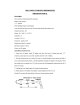
First, the Batteries
The battery compartment is located in the handle of the unit.
The unit is shipped with an empty battery pack for non-rechargeable batteries installed in the
battery compartment.
Battery Lock Tab
Remove the empty battery pack from the battery compartment.
The battery pack can be removed by sliding the lock tab towards the trigger.
Move the lock tab in this direction
Once the lock is released, the battery pack will slide down. Tilt the top of the unit up to slide
the battery pack out.
Battery pack slides out
(AA batteries not included)
Figure 1. Removing the Battery Pack
July 1, 2003 - 10 - Version 1.0
i
i
Tel: (01943) 602001- WWW.ISSLTD.CO.UK - Fax: (01943) 816796

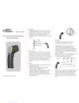
At this point, you have two options: insert six new AA batteries into the empty non-
rechargeable batteries pack or replace it with the supplied rechargeable battery pack. You will
notice the difference between the two battery packs as shown in Figure 2 below:
Non-rechargeable battery pack
(batteries not included)
Rechargeable battery pack
Figure 2. Battery Packs
To replace the battery pack just slide it back in, making sure the plastic tab lock is in the
unlocked position (to the right of the pack). Use the rails on battery pack as guides. Once it
is inserted, slide the lock tab back into the locked position as shown below in Figure 3.
Keep the lock tab in the unlocked position
Move the lock tab back to the locked position
Battery pack slides in
Figure 3. Installing Batteries
July 1, 2003 - 11 - Version 1.0
i
i
Tel: (01943) 602001- WWW.ISSLTD.CO.UK - Fax: (01943) 816796

Charging the Rechargeable Battery Pack
Connect the docking station to a power
outlet using the supplied universal
power adapter. Be sure to use the plug
adapter that fits your local electrical
standards. Connect the power jack of
the power adaptor to the DC power
inlet located on the docking station.
DC Power inlet
USB cable
Docking Station
Normal Charge Cycle
x With the ThermoView unit powered off, place it on the docking station.
x Do not connect the USB cable to the computer at this point.
x The red LED (on the left) will flash several times as the circuit senses a rechargeable
battery pack and determines its state of charge.
Note:
If a non-rechargeable battery pack is sensed by the docking station, neither LED
will blink.
The remaining points assume that the imager contains a sealed, rechargeable battery pack.
x The red LED turns on continuously to indicate that charging is in progress. This process
can take from a few minutes to more than an hour.
x The red LED turns off once the battery pack is fully charged and the green LED (on the
right) turns on continuously.
x Momentarily lifting the ThermoView unit from the docking station for about 5 seconds
or longer interrupts the charging process. The green light will come on and no further
charging will occur. Press the Restart / Sync button between the LEDs to resume
charging. Pressing the button if the batteries are completely charged will have no effect.
x The imager may be removed from the docking station before recharging is completed
without harm. However, the imager may not be fully charged and its operating time may
be reduced accordingly.
x An imager containing single-use batteries may safely be placed on the docking station for
storage or image transfer. In fact, we recommend the imager always be placed on the
docking station when not in use.
July 1, 2003 - 12 - Version 1.0
i
i
Tel: (01943) 602001- WWW.ISSLTD.CO.UK - Fax: (01943) 816796

A charge cycle takes a rechargeable battery pack from whatever level of charge it presently
has and brings it to a fully charged condition. The charger will not over-charge a battery pack
no matter how many times the button is pushed.
ght
Restart / Sync button
GREEN
light
RED
li
Figure 4. Docking Station LED Indicators
Note:
You may download stored images from the ThermoView imager to a personal
computer if the docking station’s USB cable is connected to a computer running
the InsideIR software. Press the Restart / Sync button to transfer stored images to
the computer (see Chapter 3 Downloading and Looking at Images for details).
Pressing the Restart / Sync button also starts the charging cycle.
Once the batteries are charged, you are ready to begin taking thermal images and
temperature measurements. Take a moment now to read the next section and become
acquainted with the basic features and controls of the imager.
July 1, 2003 - 13 - Version 1.0
i
i
Tel: (01943) 602001- WWW.ISSLTD.CO.UK - Fax: (01943) 816796

Chapter 2 Getting Started
Your ThermoView imager has settings and capabilities that let you customize its
operation for the task at hand. The following section describes each setting on the
imager.
Attaching the Wrist Strap
Your ThermoView imager comes with a wrist strap, which can be attached by
clipping the metal part of the strap to the small metal bar at the base of the imager
(see Figure 5 below).
Attach wrist strap
Figure 5. Attaching the Wrist Strap
July 1, 2003 - 14 - Version 1.0
i
i
Tel: (01943) 602001- WWW.ISSLTD.CO.UK - Fax: (01943) 816796

Turning the Unit On
Power is switched on or off by opening or closing the lens door. Sliding down the
lens door turns the imager on (see Figure 6 below). Slide the door up to turn off the
imager.
Open
(Unit
On
)
Closed
(Unit
Off
)
Figure 6. Powering the ThermoView Imager On and Off
Note:
The unit is self-protected against excessive levels of infrared radiation and it will
cause the unit to automatically shut down. If that happens, slide the lens door
closed, wait a minute and slide it open again.
Important:
Always dock the imager in the docking station when not in use. By doing so,
you will assure the batteries will be always fully charged when using the
rechargeable battery pack. The image will not show thermal images or
respond to controls while it is in the docking station.
Displaying Images
The ThermoView imager performs an initial auto-check each time it is activated and then
immediately shows the Information Screen. The Information Screen displays the
following information about the ThermoView imager unit:
July 1, 2003 - 15 - Version 1.0
i
i
Tel: (01943) 602001- WWW.ISSLTD.CO.UK - Fax: (01943) 816796

x Unit Serial Number
x Date and Time (configured by the user through the software)
x Tag name is the name of the user-defined folder from which data was uploaded
through the software. Useful tag names are department names or area associated
with the unit. This space is blank until configured by the user.
x Station is the name of the networked computer associated with a specific unit. This
is blank until configured by the user.
x Palette is the type of palette currently selected
x Firmware revisions
x Icons for LCD illumination, palette type, measurement mode and laser status
Figure 7. The Information Screen
Press the MODE button to exit the Information Screen. (Refer to Figure 9, the MODE
button is located center, below the LCD screen.) The ThermoView imager immediately goes
into measurement mode, showing a real time thermal image of what is in front of the lens. A
reticle with a crosshatch at the center of the display shows the temperature spot.
Note:
Do not change any of the settings yet. User configurable parameters will be
explained later in Figure 31.
July 1, 2003 - 16 - Version 1.0
i
i
Tel: (01943) 602001- WWW.ISSLTD.CO.UK - Fax: (01943) 816796

Figure 8. Normal Mode
Mode icon Palette iconLCD backlight icon
Target Temperature
Emissivity value
Location name
Temperature scale
Take time to experiment with the imager and become familiar with how the thermal image is
updated on the display as you aim the imager at different targets with different thermal
patterns. Notice how images display in varying colors, which are related to the different
target temperatures. The color scale at the bottom of the thermal image shows the minimum
and maximum temperature value in the thermal scene at any moment. These values will
change as you point the imager at other targets, or if the temperatures of the current target
change. The sequence or progression of different colors along the color scale indicates the
distribution of the different temperatures on the thermal scene. Notice how the colors along
the beginning of the color scale represent lower temperatures and colors along the end of
the color scale represent higher temperatures.
Note:
At this point you probably have noticed that the image freezes briefly from time to
time while an hourglass icon is briefly displayed. This is a normal process that
happens when the unit momentarily shuts down the optical channel to eliminate
offset errors. This is a recalibration sequence that begins immediately after the unit
is turned on. Recalibration occurs at 5 seconds, then 10 seconds, then 20 seconds,
then 30 seconds and then finally at every other minute. It is a good idea to keep the
unit On if you are using it constantly over a period of time to avoid resetting the
recalibration procedure counter.
The ThermoView imager settings can be customized for your particular application. The
following sub-section reviews the settings and controls.
July 1, 2003 - 17 - Version 1.0
i
i
Tel: (01943) 602001- WWW.ISSLTD.CO.UK - Fax: (01943) 816796

Settings and Controls
Keypad
Three buttons located below the LCD screen allow you to select operation modes and
change parameter values. These buttons are the MODE button, the Up button, and the
Down button. The Up and Down buttons are used mostly to increment and decrement
parameter values. They activate some special functions as well. The MODE button is used
mostly to cycle between the different operations. Details about the function of each button
are discussed later.
Down
button
MODE
button
Up
button
Figure 9. Keypad Controls
A hinged door on the top surface of the ThermoView imager hides five switches that allow
you to change the basic imager settings. Open the hinged door by lifting it up.
July 1, 2003 - 18 - Version 1.0
i
i
Tel: (01943) 602001- WWW.ISSLTD.CO.UK - Fax: (01943) 816796

Pull door up to
show control
switches
Push buttons
(toggle)
3-position
Switches
Thumbwheels
Figure 10. ThermoView Imager Settings Switches (icons not shown)
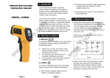
The illustration below shows the top view of the switch bay without the door. There is an
icon printed near each switch and near each switch position indicating the function of each
switch and switch position. These functions are explained in the next paragraphs.
July 1, 2003 - 19 - Version 1.0
i
i
Tel: (01943) 602001- WWW.ISSLTD.CO.UK - Fax: (01943) 816796

Figure 11. ThermoView Imager Settings Switches
Laser On/Off Toggle Button
LCD backlight selection
Palette selection
Measurement mode selection
Level ad
j
ustment
Gain ad
j
ustment
Laser ON/OFF
Centigrade /
Fahrenheit selection
The Laser On/Off toggle button switches the laser on and off. By default, the guiding
tion you may or may not need the laser guidancelaser beam is off. Depending on the situa
beam.
July 1, 2003 - 20 - Version 1.0
i
i
Tel: (01943) 602001- WWW.ISSLTD.CO.UK - Fax: (01943) 816796
/