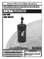
Harbor Freight Tools 60802 Owner's manual
- Category
- Power tools
- Type
- Owner's manual
This manual is also suitable for


Page 2 For technical questions, please call 1-800-444-3353. Item 60801 / 60802
SAFETY OPERATION MAINTENANCESETUP
Table of Contents
Safety ......................................................... 2
Specifications ............................................. 6
Setup .......................................................... 7
Operation .................................................... 8
Maintenance .............................................. 10
Parts List and Diagram .............................. 11
Warranty .................................................... 12
WARNING SYMBOLS AND DEFINITIONS
This is the safety alert symbol. It is used to alert you to potential personal injury hazards.
Obey all safety messages that follow this symbol to avoid possible injury or death.
Indicates a hazardous situation which, if not avoided,
will result in death or serious injury.
Indicates a hazardous situation which, if not avoided,
could result in death or serious injury.
Indicates a hazardous situation which, if not avoided,
could result in minor or moderate injury.
Addresses practices not related to personal injury.
IMPORTANT SAFETY INSTRUCTIONS
INSTRUCTIONS PERTAINING TO A RISK OF FIRE,
ELECTRIC SHOCK, OR INJURY TO PERSONS
WARNING – When using tools, basic precautions should always be followed, including the following:
General
To reduce the risks of electric shock, fire, and injury to persons, read all the instructions before using the tool.
Work Area
1. Keep the work area clean and well lighted.
Cluttered benches and dark areas increase the
risks of electric shock, fire, and injury to persons.
2. Do not operate the tool in explosive atmospheres,
such as in the presence of flammable liquids,
gases, or dust. The tool is able to create sparks
resulting in the ignition of the dust or fumes.
3. Keep bystanders, children, and visitors away
while operating the tool. Distractions are able
to result in the loss of control of the tool.

Page 3For technical questions, please call 1-800-444-3353.Item 60801 / 60802
SAFETYOPERATIONMAINTENANCE SETUP
Personal Safety
1. Stay alert. Watch what you are doing and
use common sense when operating the tool.
Do not use the tool while tired or under the
influence of drugs, alcohol, or medication.
A moment of inattention while operating the
tool increases the risk of injury to persons.
2. Dress properly. Do not wear loose
clothing or jewelry. Contain long hair.
Keep hair, clothing, and gloves away from
moving parts. Loose clothes, jewelry, or long
hair increases the risk of injury to persons as
a result of being caught in moving parts.
3. Avoid unintentional starting. Be sure the switch
is off before connecting to the air supply.
Do not carry the tool with your finger on the switch or
connect the tool to the air supply with the switch on.
4. Do not overreach.
Keep proper footing and balance at all times.
Proper footing and balance enables better
control of the tool in unexpected situations.
5. Use safety equipment.
A dust mask, non-skid safety shoes and
a hard hat must be used for the
applicable conditions.
6. Always wear eye protection.
Wear ANSI-approved safety goggles.
7. Always wear hearing protection
when using the tool.
Prolonged exposure to high intensity
noise is able to cause hearing loss.
8. Wear heavy-duty work gloves during use.
Tool Use and Care
1. Use clamps or another practical way to secure
and support the workpiece to a stable platform.
Holding the work by hand or against the body is
unstable and is able to lead to loss of control.
2. Do not force the tool. Use the correct tool for the
application. The correct tool will do the job better
and safer at the rate for which the tool is designed.
3. Do not use the tool if the switch does not turn the
tool on or off. Any tool that cannot be controlled
with the switch is dangerous and must be repaired.
4. Disconnect the tool from the air source before
making any adjustments, changing accessories,
or storing the tool. Such preventive safety
measures reduce the risk of starting the tool
unintentionally. Turn off and detach the air supply,
safely discharge any residual air pressure, and
release the throttle and/or turn the switch to its
off position before leaving the work area.
5. Store the tool when it is idle out of reach
of children and other untrained persons.
A tool is dangerous in the hands of untrained users.
6. Maintain the tool with care.
A properly maintained tool is easier to control.
7. Check for misalignment or binding of moving
parts, breakage of parts, and any other condition
that affects the tool's operation. If damaged,
have the tool serviced before using. Many accidents
are caused by poorly maintained tools.
There is a risk of bursting if the tool is damaged.
8. Use only accessories that are identified by the
manufacturer for the specific tool model. Use of
an accessory not intended for use with the specific
tool model, increases the risk of injury to persons.
Service
1. Tool service must be performed only
by qualified repair personnel.
2. When servicing a tool, use only identical
replacement parts. Use only authorized parts.
3. Use only the lubricants supplied with the tool or
specified by the manufacturer.
Do not use any lubricants with this tool.

Page 4 For technical questions, please call 1-800-444-3353. Item 60801 / 60802
SAFETY OPERATION MAINTENANCESETUP
Air Source
1. Never connect to an air source that is
capable of exceeding 200 psi.
Over pressurizing the tool may cause
bursting, abnormal operation, breakage
of the tool or serious injury to persons.
Use only clean, dry, regulated compressed air at the
rated pressure or within the rated pressure range as
marked on the tool. Always verify prior to using the
tool that the air source has been adjusted to the rated
air pressure or within the rated air-pressure range.
2. Never use oxygen, carbon dioxide, combustible
gases or any bottled gas as an air source
for the tool. Such gases are capable of
explosion and serious injury to persons.
SAVE THESE INSTRUCTIONS.
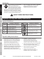
Symbols and Specific Safety Instructions
Symbol Definitions
Symbol Property or statement
PSI
Pounds per square inch of pressure
CFM
Cubic Feet per Minute flow
SCFM
Cubic Feet per Minute flow
at standard conditions
NPT
National pipe thread, tapered
NPS
National pipe thread, straight
Symbol Property or statement
WARNING marking
concerning Risk of Eye Injury.
Wear ANSI-approved eye protection.
WARNING marking concerning Risk of
Hearing Loss. Wear hearing protection.
WARNING marking concerning
Risk of Respiratory Injury. Wear
NIOSH-approved dust mask/respirator.
WARNING marking concerning
Risk of Explosion.
Specific Safety Instructions
1. The warnings and precautions discussed in this
manual cannot cover all possible conditions and
situations that may occur. It must be understood
by the operator that common sense and caution
are factors which cannot be built into this
product, but must be supplied by the operator.
2. DO NOT DROP TANK, RISK OF EXPLOSION.
3. WARNING: This product, when used for abrasive
blasting and similar applications, produces chemicals
known to the State of California to cause cancer
and birth defects (or other reproductive harm).
(California Health & Safety Code § 25249.5, et seq.)
4. WARNING: The brass components of
this product contain lead, a chemical
known to the State of California to cause
birth defects (or other reproductive harm).
(California Health & Safety code § 25249.5, et seq.)
5. Attach all accessories properly to the Soda Blaster
before connecting the air supply. A loose
accessory may detach or break during operation.
6. Obey the manual for the air compressor
used to power this Soda Blaster.
7. Install an in-line shutoff valve to allow
immediate control over the air supply in an
emergency, even if a hose is ruptured.

Page 5For technical questions, please call 1-800-444-3353.Item 60801 / 60802
SAFETYOPERATIONMAINTENANCE SETUP
Silicosis and Aluminum Oxide Warnings
WARNING! Abrasive blasting with sand containing
crystalline silica can cause serious or fatal respiratory
disease. Exposure to crystalline silica may cause
silicosis (a serious lung disease), cancer and death.
Exposure to aluminum oxide (a dust generated from
material removing processes) can result in eye, skin
and breathing irritation. Always use a NIOSH (National
Institute for Occupational Safety and Health) approved
respirator and safety goggles. Avoid skin exposure.
Proper ventilation in the work area is required. Read
and understand the 10 recommended measures below
to reduce crystalline silica exposures in the workplace
and prevent silicosis and silicosis related deaths.
NIOSH recommends the following measures to
reduce crystalline silica exposures in the workplace
and prevent silicosis and silicosis-related deaths:
1. Prohibit silica sand (or other substances
containing more than 1% crystalline silica)
as an abrasive blasting material and
substitute less hazardous materials.
2. Conduct air monitoring to measure worker exposures.
3. Use containment methods such as blast-cleaning
machines and cabinets to control the hazard
and protect adjacent workers from exposure.
4. Practice good personal hygiene to avoid
unnecessary exposure to silica dust.
5. Wear washable or disposable protective clothes
at the work site. Shower and change into clean
clothes before leaving the work site to prevent
contamination of cars, homes and other work areas.
6. Use respiratory protection when source controls
cannot keep silica exposures below the NIOSH REL.
7. Provide periodic medical examinations for all
workers who may be exposed to crystalline silica.
8. Post signs to warn workers about the hazard and to
inform them about required protective equipment.
9. Provide workers with training that includes
information about health effects, work practices
and protective equipment for crystalline silica.
10. Report all cases of silicosis to State health
departments and to OSHA or the Mine Safety
and Health Administration (MSHA).
Vibration Precautions
This tool vibrates during use. Repeated or long-term
exposure to vibration may cause temporary or permanent
physical injury, particularly to the hands, arms and
shoulders. To reduce the risk of vibration-related injury:
1. Anyone using vibrating tools regularly or for an
extended period should first be examined by a
doctor and then have regular medical check-ups to
ensure medical problems are not being caused or
worsened from use. Pregnant women or people who
have impaired blood circulation to the hand, past
hand injuries, nervous system disorders, diabetes,
or Raynaud's Disease should not use this tool.
If you feel any symptoms related to vibration (such
as tingling, numbness, and white or blue fingers),
seek medical advice as soon as possible.
2. Do not smoke during use. Nicotine reduces
the blood supply to the hands and fingers,
increasing the risk of vibration-related injury.
3. Wear suitable gloves to reduce the
vibration effects on the user.
4. Use tools with the lowest vibration
when there is a choice.
5. Include vibration-free periods each day of work.
6. Grip tool as lightly as possible (while still keeping
safe control of it). Let the tool do the work.
7. To reduce vibration, maintain
tool as explained in this manual.
If abnormal vibration occurs, stop immediately.
SAVE THESE INSTRUCTIONS.

Page 6 For technical questions, please call 1-800-444-3353. Item 60801 / 60802
SAFETY OPERATION MAINTENANCESETUP
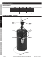
Functional Description
Specifications
ITEM 60801 60802
Maximum Air Pressure 90 PSI
Air Inlet 1/4″ -18 NPT
Average Air Consumption 8.5 CFM @ 90 PSI 7 CFM @ 90 PSI
Abrasive Capacity 40 lb. 15 lb.
Abrasive Type Sodium Bicarbonate media only
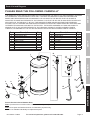
Components and Controls
Tank
Air Valve
Air
Regulator
Knob
Media
Regulator
Knob
Media
Valve
Safety
Valve
Pressure
Gauge
Nozzle

Page 7For technical questions, please call 1-800-444-3353.Item 60801 / 60802
SAFETYOPERATIONMAINTENANCE SETUP
Initial Soda Blaster Set Up/Assembly
Read the ENTIRE IMPORTANT SAFETY INFORMATION section at the beginning of this
manual including all text under subheadings therein before set up or use of this product.
Note: For additional information regarding the parts listed in the following pages,
refer to the Assembly Diagram near the end of this manual.
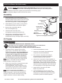
Assembly
1. Wrap the threads of the Pressure Gauge (7)
with thread sealer tape (not included). Screw the
Pressure Gauge into the opening in the face of the
Air Regulator (9). Tighten using a wrench on the
back of the Gauge block. Do not overtighten.
2. Attach Bracket (3) to the Tank (1) using the two
Socket Head Screws (4) and wrench tighten.
3. Remove the Compression Nut (2)
from the Air Regulator (9).
4. Insert the knob on the top of the
Air Regulator (9) through the Bracket (3).
5. Align the tab on the Bracket with the recess
at gauge side of the Regulator, attach
Compression Nut (2), and finger tighten until snug.
Bracket (3)
Socket Head
Screws (4)
Pressure
Gauge (7)
Air
Regulator (9)
Compression
Nut (2)
Tank (1)
Figure A: Air Regulator Assembly
Air Supply
TO PREVENT SERIOUS INJURY FROM EXPLOSION:
Use only clean, dry, regulated, compressed air to power this Soda Blaster.
Do not use oxygen, carbon dioxide, combustible gases,
or any other bottled gas as a power source for this Soda Blaster.
1. Incorporate a filter, regulator with pressure
gauge, dryer, in-line shutoff valve, and quick
coupler for best service. An in-line shutoff ball
valve is an important safety device because
it controls the air supply even if the air hose
is ruptured. The shutoff valve should be a
ball valve because it can be closed quickly.
Note: An oiler system should not be used with this
Soda Blaster. The oil will mix with the material
being propelled, causing poor results.
2. Attach an air hose to the compressor's air outlet.
Connect the air hose to the air valve
of the Soda Blaster. Other components, such
as a coupler plug and quick coupler, will make
operation more efficient, but are not required.
Note: Air flow, and therefore Soda Blaster
performance, can be hindered by undersized air
supply components. The air hose must be long
enough to reach the work area with enough extra
length to allow free movement while working.
3. Close the Soda Blaster’s valves.
4. Close the in-line shutoff valve between the
compressor and the Soda Blaster.
5. Turn on the air compressor according to
the manufacturer's directions and allow it
to build up pressure until it cycles off.
6. Adjust the air compressor's output regulator so
that the air output is enough to properly power the
Soda Blaster, but the output will not exceed the
Soda Blaster's maximum air pressure at any time.
Adjust the pressure gradually, while checking the
air output gauge to set the right pressure range.
7. Inspect the air connections for leaks.
Repair any leaks found.
8. If the Soda Blaster will not be used at this
time, turn off and detach the air supply, safely
discharge any residual air pressure, and close
the valves to prevent accidental operation.

Page 8 For technical questions, please call 1-800-444-3353. Item 60801 / 60802
SAFETY OPERATION MAINTENANCESETUP
Operating Instructions
Read the ENTIRE IMPORTANT SAFETY INFORMATION section at the beginning of this
manual including all text under subheadings therein before set up or use of this product.
Inspect Soda Blaster before use, looking for damaged, loose, and missing parts.
If any problems are found, do not use Soda Blaster until repaired.
Tool Set Up - Loading Abrasive
TO PREVENT SERIOUS INJURY FROM ACCIDENTAL OPERATION:
Close all Valves, detach the air supply, safely discharge any residual air pressure in the Soda Blaster,
and close all Valves again before performing any procedure in this section.
TO PREVENT SERIOUS INJURY:
Do not adjust or tamper with any control or component in a way not specifically explained within
this manual. Improper adjustment can result in Soda Blaster failure or other serious hazards.
Use sodium bicarbonate blast media only.
WARNING! Do not use sand or other blasting
materials that contain crystalline silica.
Note: Use only dry and clean abrasives
to avoid clogging the Soda Blaster.
Note: The Nozzle size depends on grit of media used.
Change the nozzle as needed to suit the abrasive.
1. Pull back on the blue Air Hose Connector (8)
collar and pull out Air Hose (15).
2. Hold collar on Tank (1) with a wrench and use
another wrench to loosen Bushing (10).
(Wrenches not included.)
3. Remove entire media discharge assembly slowly,
being careful with the Pickup Tube (11) as it may
contain residual media which can spill when
removed. Allow time for the trapped aggregate
to safely discharge back into the Tank.
4. Using a funnel, pour media into the Tank.
Note: If this is a large job, fill the Tank only 3/4 full
and reload as needed to finish the job.
Note: If the humidity is 90 to 100%, reduce the amount
of media and refill more frequently to reduce clogging.
5. Inspect condition of the O-ring (19) at the bottom
of the Bushing, and replace if damaged.
6. Insert the Pickup Tube into the Tank and
tighten the Bushing. Do not over tighten.
7. Pull back on the blue Air Hose Connector
collar and insert the Air Hose deep into the
fitting. Release the collar.
Note: If air leaks around the Air Hose, remove it,
cut approximately a quarter of an inch off and reattach it.
8. Turn on the compressor and set the
regulator to the pressure recommended
for this Soda Blaster (90 PSI).
CAUTION! Do not exceed 90 PSI.

Page 9For technical questions, please call 1-800-444-3353.Item 60801 / 60802
SAFETYOPERATIONMAINTENANCE SETUP
Workpiece and Work Area Set Up
1. Designate a work area that is clean and well-lit.
The work area must not allow access by children
or pets to prevent distraction and injury.
2. Route the air hose along a safe route to reach
the work area without creating a tripping hazard
or exposing the air hose to possible damage.
The air hose must be long enough to reach
the work area with enough extra length to
allow free movement while working.
3. Secure loose workpieces using a vise or clamps
(not included) to prevent movement while working.
4. There must not be hazardous objects
(such as utility lines or foreign objects) nearby
that will present a hazard while working.
General Operating Instructions
1. If possible, place the workpiece inside a
sandblast cabinet. Otherwise, isolate the
workpiece to make sure no damage can
occur to nearby personal property.
2. Open the Air Valve.
3. Grip the Media Hose and Nozzle firmly,
and point them at the start point. Open the
Media Valve completely to release the media.
NOTICE: To prevent damage, only use
the Media Valve to turn the flow on or off.
Do not use it to adjust the flow rate. Only use the
Media Regulator Knob to adjust the flow rate.
4. Spray the abrasive media onto the work material,
moving the Nozzle from side to side.
NOTE: The flow rate of the media may be irregular
when first started. Provided the media is dry,
the flow rate will normalize in approximately one minute.
5. Use Media Regulator Knob to
adjust the media flow rate.
6. Adjust the Air Regulator to adjust the air flow and
pressure. Do not set the pressure higher than 90 PSI.
7. If the Soda Blaster requires more force to accomplish
the task, verify that the Soda Blaster receives
sufficient, unobstructed airflow (CFM) and increase
the pressure (PSI) output of the regulator up to the
maximum air pressure rating of this Soda Blaster.
CAUTION! TO PREVENT SODA BLASTER AND
ACCESSORY FAILURE, RESULTING IN INJURY:
Do not exceed the Soda Blaster’s maximum air
pressure rating.
If the Soda Blaster still does not have sufficient
force at maximum pressure and sufficient airflow,
then a larger Soda Blaster may be required.
8. If excessive air pressure is used, or Media Regulator
becomes clogged, the Safety Valve may open,
releasing air pressure. To correct:
a. Shut OFF Air Valve.
b. Adjust Air Regulator to below 90 PSI.
c. Turn the Air Valve back on.
d. If the problem happens again,
detach the air supply and clean out the
Media Regulator and Media Hose.
9. To prevent accidents, close the Valves on the
Soda Blaster, detach the air supply, safely
discharge any residual air pressure in the
Soda Blaster, and close the Valves again. Empty
the Tank, and clean external surfaces of the
Soda Blaster with clean, dry cloth. Then store the
Soda Blaster indoors out of children’s reach.

Page 10 For technical questions, please call 1-800-444-3353. Item 60801 / 60802
SAFETY OPERATION MAINTENANCESETUP
User-Maintenance Instructions
Procedures not specifically explained in this manual must
be performed only by a qualified technician.
TO PREVENT SERIOUS INJURY FROM ACCIDENTAL OPERATION:
Turn off the Soda Blaster, detach the air supply, safely discharge any residual air pressure
in the Soda Blaster, and release the throttle and/or turn the switch to its off position
before performing any inspection, maintenance, or cleaning procedures.
TO PREVENT SERIOUS INJURY FROM SODA BLASTER FAILURE:
Do not use damaged equipment. If abnormal noise, vibration,
or leaking air occurs, have the problem corrected before further use.
Cleaning, Maintenance, and Lubrication
Note: These procedures are in addition to the regular checks and maintenance
explained as part of the regular operation of the air-operated Soda Blaster.
1. BEFORE EACH USE, inspect the general
condition of the Soda Blaster. Check for:
• loose hardware or housing,
• misalignment or binding of moving parts,
• cracked or broken parts, and
• any other condition that may
affect its safe operation.
2. Daily - Air Supply Maintenance:
Every day, maintain the air supply according
to the component manufacturers' instructions.
Drain the moisture filter regularly.
Performing routine air supply maintenance will
allow the Soda Blaster to operate more safely
and will also reduce wear on the Soda Blaster.
Troubleshooting
1. Excess moisture will cause the abrasive to slow
or stop flowing through the Abrasive Outlet Pipe.
To test, check the abrasive by pouring a 6″ cone
of abrasive on dry newspaper. After several
minutes, remove the abrasive from the newspaper.
Do not use the abrasive if the newspaper is moist.
2. Poor or irregular flow of the abrasive may also be due
to low air pressure or a worn Nozzle.
To correct, increase the air pressure
(to no more than 90 PSI) and/
or replace the worn Nozzle.

Page 11For technical questions, please call 1-800-444-3353.Item 60801 / 60802
SAFETYOPERATIONMAINTENANCE SETUP
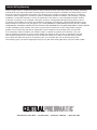
Parts List and Diagram
PLEASE READ THE FOLLOWING CAREFULLY
THE MANUFACTURER AND/OR DISTRIBUTOR HAS PROVIDED THE PARTS LIST AND ASSEMBLY DIAGRAM
IN THIS MANUAL AS A REFERENCE TOOL ONLY. NEITHER THE MANUFACTURER OR DISTRIBUTOR
MAKES ANY REPRESENTATION OR WARRANTY OF ANY KIND TO THE BUYER THAT HE OR SHE IS
QUALIFIED TO MAKE ANY REPAIRS TO THE PRODUCT, OR THAT HE OR SHE IS QUALIFIED TO REPLACE
ANY PARTS OF THE PRODUCT. IN FACT, THE MANUFACTURER AND/OR DISTRIBUTOR EXPRESSLY
STATES THAT ALL REPAIRS AND PARTS REPLACEMENTS SHOULD BE UNDERTAKEN BY CERTIFIED AND
LICENSED TECHNICIANS, AND NOT BY THE BUYER. THE BUYER ASSUMES ALL RISK AND LIABILITY
ARISING OUT OF HIS OR HER REPAIRS TO THE ORIGINAL PRODUCT OR REPLACEMENT PARTS
THERETO, OR ARISING OUT OF HIS OR HER INSTALLATION OF REPLACEMENT PARTS THERETO.
Part Description Qty
1 Tank 1
2 Compression Nut 1
3 Bracket 1
4 Socket Head Screw 2
5 Male Coupler 1
6 Air Valve 1
7 Pressure Gauge 1
8 Air Hose Connector 2
9 Air Regulator 1
10 Bushing 1
Part Description Qty
11 Pickup Tube 1
12 Media Valve 1
13 Media Regulator Asm. 1
14 Safety Valve 1
15 Air Hose 1
16 Media Hose 1
17 Nozzle Capnut 1
18 Ceramic Nozzle 1
19 O-Ring 1
1
2
3
4
5
6
7
8
9
10
11
12
13
14
15
16
17
18
8
19
Record Product's Serial Number Here:
Note: If product has no serial number, record month and year of purchase instead.
Note: Some parts are listed and shown for illustration purposes only,
and are not available individually as replacement parts.

Limited 90 Day Warranty
Harbor Freight Tools Co. makes every effort to assure that its products meet high quality and durability standards,
and warrants to the original purchaser that this product is free from defects in materials and workmanship for the
period of 90 days from the date of purchase. This warranty does not apply to damage due directly or indirectly,
to misuse, abuse, negligence or accidents, repairs or alterations outside our facilities, criminal activity, improper
installation, normal wear and tear, or to lack of maintenance. We shall in no event be liable for death, injuries
to persons or property, or for incidental, contingent, special or consequential damages arising from the use of
our product. Some states do not allow the exclusion or limitation of incidental or consequential damages, so the
above limitation of exclusion may not apply to you. THIS WARRANTY IS EXPRESSLY IN LIEU OF ALL OTHER
WARRANTIES, EXPRESS OR IMPLIED, INCLUDING THE WARRANTIES OF MERCHANTABILITY AND FITNESS.
To take advantage of this warranty, the product or part must be returned to us with transportation charges
prepaid. Proof of purchase date and an explanation of the complaint must accompany the merchandise.
If our inspection verifies the defect, we will either repair or replace the product at our election or we may
elect to refund the purchase price if we cannot readily and quickly provide you with a replacement. We will
return repaired products at our expense, but if we determine there is no defect, or that the defect resulted
from causes not within the scope of our warranty, then you must bear the cost of returning the product.
This warranty gives you specific legal rights and you may also have other rights which vary from state to state.
3491 Mission Oaks Blvd. • PO Box 6009 • Camarillo, CA 93011 • (800) 444-3353
-
 1
1
-
 2
2
-
 3
3
-
 4
4
-
 5
5
-
 6
6
-
 7
7
-
 8
8
-
 9
9
-
 10
10
-
 11
11
-
 12
12


Harbor Freight Tools 60802 Owner's manual
- Category
- Power tools
- Type
- Owner's manual
- This manual is also suitable for
Ask a question and I''ll find the answer in the document
Finding information in a document is now easier with AI
Related papers
-
Harbor Freight Tools Item 60491 Owner's manual
-
Pittsburgh Automotive Item 61251 Owner's manual
-
Harbor Freight Tools 93889 User manual
-
-
Harbor Freight Tools 3/8 in. Butterfly Air Impact Wrench Owner's manual
-
-
-
-
-
Other documents
-
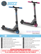 REVOE Pack enfant Buzz Bleu Owner's manual
-
Central Pneumatic 60802 Owner's manual
-
HARBOR FREIGHT 60801 Owner's manual
-
-
-
TEC Air Flow Method User manual
-
-
-
-
Buffalo SBC90 Owner's manual
