
USER'S MANUAL
Serial
Number
Decal
Model No. WLTL27308.0
Serial No.
QUESTIONS?
As a manufacturer, we are commit-
ted to providing complete customer
satisfaction. If you have questions,
or if parts are missing, PLEASE DO
NOT CONTACT THE STORE;
please contact Customer Care.
IMPORTANT: You must note the
product model number and ser-
ial number (see the drawing
above) before contacting us:
CALL TOLL-FREE:
1-866-699-3756
Mon.–Fri. 6 a.m.–6 p.m. MST
Sat. 8 a.m.–4 p.m. MST
ON THE WEB:
www.wesloservice.com
CAUTION
Read all precautions and instruc-
tions in this manual before using
this equipment. Save this manual
for future reference.
Visit our website at
www.weslo.com
new products, prizes,
fitness tips, and much more!
V
Write the serial number in the
space above for future reference.

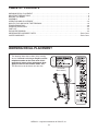
TABLE OF CONTENTS
WARNING DECAL PLACEMENT . . . . . . . . . . . . . . . . . . . . . . . . . . . . . . . . . . . . . . . . . . . . . . . . . . . . . . . . . . . . . .2
I
MPORTANT PRECAUTIONS . . . . . . . . . . . . . . . . . . . . . . . . . . . . . . . . . . . . . . . . . . . . . . . . . . . . . . . . . . . . . . . . .3
BEFORE YOU BEGIN . . . . . . . . . . . . . . . . . . . . . . . . . . . . . . . . . . . . . . . . . . . . . . . . . . . . . . . . . . . . . . . . . . . . . . .5
ASSEMBLY . . . . . . . . . . . . . . . . . . . . . . . . . . . . . . . . . . . . . . . . . . . . . . . . . . . . . . . . . . . . . . . . . . . . . . . . . . . . . . .6
OPERATION AND ADJUSTMENT . . . . . . . . . . . . . . . . . . . . . . . . . . . . . . . . . . . . . . . . . . . . . . . . . . . . . . . . . . . .13
HOW TO FOLD AND MOVE THE TREADMILL . . . . . . . . . . . . . . . . . . . . . . . . . . . . . . . . . . . . . . . . . . . . . . . . . .18
TROUBLESHOOTING . . . . . . . . . . . . . . . . . . . . . . . . . . . . . . . . . . . . . . . . . . . . . . . . . . . . . . . . . . . . . . . . . . . . . .20
EXERCISE GUIDELINES . . . . . . . . . . . . . . . . . . . . . . . . . . . . . . . . . . . . . . . . . . . . . . . . . . . . . . . . . . . . . . . . . . .22
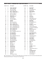
PART LIST . . . . . . . . . . . . . . . . . . . . . . . . . . . . . . . . . . . . . . . . . . . . . . . . . . . . . . . . . . . . . . . . . . . . . . . . . . . . . . .23
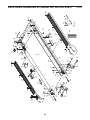
EXPLODED DRAWING . . . . . . . . . . . . . . . . . . . . . . . . . . . . . . . . . . . . . . . . . . . . . . . . . . . . . . . . . . . . . . . . . . . . .24
ORDERING REPLACEMENT PARTS . . . . . . . . . . . . . . . . . . . . . . . . . . . . . . . . . . . . . . . . . . . . . . . . . .Back Cover
LIMITED WARRANTY . . . . . . . . . . . . . . . . . . . . . . . . . . . . . . . . . . . . . . . . . . . . . . . . . . . . . . . . . . . . . . .Back Cover
WESLO is a registered trademark of ICON IP, Inc.
2
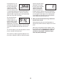
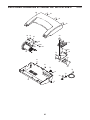
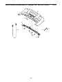
This drawing shows the locations of the warning
decals. If a decal is missing or illegible, call the
telephone number on the front cover of this
manual and request a free replacement decal.
Apply the decal in the location shown. Note:
The decals may not be shown at actual size.
WARNING DECAL PLACEMENT
(Placed on
wire harness)

3
WARNING: To reduce the risk of serious injury, read all important precautions and in-
structions in this manual and all warnings on your treadmill before using your treadmill. ICON as-
sumes no responsibility for personal injury or property damage sustained by or through the use of
this product.
IMPORTANT PRECAUTIONS
1. Before beginning any exercise program, con-
sult your physician. This is especially impor-
tant for persons over age 35 or persons with
pre-existing health problems.
2. It is the responsibility of the owner to ensure
that all users of this treadmill are adequately
informed of all warnings and precautions.
3. Use the treadmill only as described.
4. Place the treadmill on a level surface, with at
least 8 ft. (2.4 m) of clearance behind it and 2
ft. (0.6 m) on each side. Do not place the
treadmill on any surface that blocks air open-
ings. To protect the floor or carpet from dam-
age, place a mat under the treadmill.
5. Keep the treadmill indoors, away from mois-
ture and dust. Do not put the treadmill in a
garage or covered patio, or near water.
6. Do not operate the treadmill where aerosol
products are used or where oxygen is being
administered.
7. Keep children under age 12 and pets away
from the treadmill at all times.
8. The treadmill should not be used by persons
weighing more than 250 lbs. (113 kg).
9. Never allow more than one person on the
treadmill at a time.
10. Wear appropriate exercise clothes when
using the treadmill. Do not wear loose clothes
that could become caught in the treadmill.
Athletic support clothes are recommended for
both men and women. Always wear athletic
shoes; never use the treadmill with bare feet,
wearing only stockings, or in sandals.
11. When connecting the power cord (see page 13),
plug the power cord into a surge suppressor
(not included) and plug the surge suppressor
into a grounded circuit capable of carrying 15
or more amps. No other appliance should be on
the same circuit. Do not use an extension cord.
12. Use only a single-outlet surge suppressor that
meets all of the specifications described on
page 13. To purchase a surge suppressor, see
your local WESLO dealer or call the telephone
number on the front cover of this manual and
order part number 146148, or see your local
electronics store.
13. Failure to use a properly functioning surge
suppressor could result in damage to the con-
trol system of the treadmill. If the control sys-
tem is damaged, the walking belt may slow,
accelerate, or stop unexpectedly, which may
result in a fall and serious injury.
14. Keep the power cord and the surge suppres-
sor away from heated surfaces.
15. Never move the walking belt while the power
is turned off. Do not operate the treadmill if
the power cord or plug is damaged, or if the
treadmill is not working properly. (See TROU-
BLESHOOTING on page 20 if the treadmill is
not working properly.)
16. Read, understand, and test the emergency
stop procedure before using the treadmill (see
page 15).
17. Never start the treadmill while you are stand-
ing on the walking belt. Always hold the
handrails while using the treadmill.
18. The treadmill is capable of high speeds.
Adjust the speed in small increments to avoid
sudden jumps in speed.
19. Never leave the treadmill unattended while it
is running. Always remove the key, unplug the
power cord, and switch the reset/off circuit
breaker to the “off” position when the tread-
mill is not in use. (See the drawing on page 5
for the location of the reset/off circuit breaker.)

4
20. Do not attempt to raise, lower, or move the
treadmill until it is properly assembled. (See
A
SSEMBLY on page 6 and HOW TO FOLD
AND MOVE THE TREADMILL on page 18.)
You must be able to safely lift 45 lbs. (20 kg)
to raise, lower, or move the treadmill.
21. When folding or moving the treadmill, make
sure that the storage latch is holding the
frame securely in the storage position.
22. Do not change the incline of the treadmill by
placing objects under the treadmill.
23. Inspect and properly tighten all parts of the
treadmill regularly.
24. Never drop or insert any object into any
opening on the treadmill.
2
5.
DANGER: A
lways unplug the power
cord immediately after use, before cleaning
the treadmill, and before performing the main-
tenance and adjustment procedures de-
scribed in this manual. Never remove the
motor hood unless instructed to do so by an
authorized service representative. Servicing
other than the procedures in this manual
should be performed by an authorized service
representative only.
26. This treadmill is intended for in-home use
only. Do not use this treadmill in any commer-
cial, rental, or institutional setting.
SAVE THESE INSTRUCTIONS

5
Thank you for selecting the new WESLO
®
CADENCE
CT 5.8 treadmill. The CADENCE CT 5.8 treadmill of-
f
ers a selection of features designed to make your
workouts at home more effective. And when youʼre not
e
xercising, the unique CADENCE CT 5.8 treadmill can
be folded up, requiring less than half the floor space of
other treadmills.
For your benefit, read this manual carefully before
using the treadmill. If you have questions after read-
ing this manual, please see the front cover of this man-
ual. To help us assist you, note the product model
number and serial number before contacting us. The
m
odel number and the location of the serial number
decal are shown on the front cover of this manual.
To avoid a registration fee for any service needed
under warranty, you must register the treadmill at
www.wesloservice.com/registration.
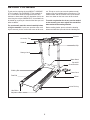
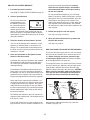
Before reading further, please review the drawing
below and familiarize yourself with the labeled parts.
BEFORE YOU BEGIN
Handrail
Storage Latch
Console
Key/Clip
Reset/Off
Circuit Breaker
Power Cord
Incline Pin/Leg
Walking Belt
Motor Hood
Wheel
Foot Rail
Idler Roller
Adjustment Bolts
Accessory Tray

6
ASSEMBLY
T
o hire an authorized service technician to assemble the treadmill, call 1-800-445-2480.
Assembly requires two persons. Set the treadmill in a cleared area and remove all packing materials; do not
dispose of the packing materials until assembly is completed. Note: The underside of the treadmill walking
b
elt is coated with high-performance lubricant. During shipping, a small amount of lubricant may be transferred to
the top of the walking belt or the shipping carton. This does not affect treadmill performance. If there is lubricant
on top of the walking belt, simply wipe off the lubricant with a soft cloth and a mild, non-abrasive cleaner.
Assembly requires the included hex keys and your own Phillips screwdriver ,
adjustable wrench , and wire cutters .
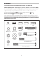
Use the drawings below to identify the assembly hardware. The number in parentheses below each drawing is
the key number of the part, from the PART LIST near the end of this manual. The number after the parentheses
is the quantity needed for assembly. Note: If a part is not in the hardware kit, check to see if it is preattached
to one of the parts to be assembled. To avoid damaging plastic parts, do not use power tools for assem-
bly. Extra hardware may be included.
M10 x 110mm Bolt (1)–2
M10 x 80mm Bolt (4)–2
M10 x 58mm Bolt (2)–4
M10 Star
Washer (11)–2
M8 x 52mm Bolt (8)–2
M4.2 x 19mm
Screw (5)–6
M5 x 16mm
Screw (9)–2
M10 Nut
(15)–2
M5 Star
Washer (13)–2
M8 Nut
(16)–2
M8 Washer
(10)–4
M10 Washer
(12)–2
M8 x 16mm
Bolt (3)–6
M4.2 x 19mm
Tek Screw (6)–6
5/16" Star
Washer (14)–6
#10 x 1" Tek Screw
(7)–2

7
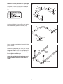
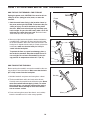
1. Make sure that the power cord is unplugged.
Attach the six Base Feet (90) to the bottom of
the Base (91) with six M4.2 x 19mm Tek Screws
(6).
3. Have a second person hold the Base (91) in the
position shown.
Identify the Right Upright (87), which has a large
hole near the lower end. Orient the Right
Upright as shown. Attach the Right Upright to
the Base (91) with two M10 x 58mm Bolts (2).
Do not tighten the Bolts yet.
Attach the Left Upright (86) to the Base (91)
in the same way. Orient the small holes as
shown.
91
6
6
90
9
0
1
6
6
6
90
90
90
2. Attach each Wheel (92) to the Base (91) with an
M10 x 80mm Bolt (4) and an M10 Nut (15).
92
4
2
4
15
15
3
87
Small
Holes
2
92
Large
Hole
91
86
2
91

8
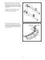
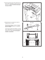
5. Have a second person lift and hold the front end
of the Frame (61). Hold an Upright Spacer (88)
between the Right Upright (87) and the Frame.
Attach the Right Upright to the Frame with an
M10 x 110mm Bolt (1), an M10 Washer (12), and
an M10 Star Washer (11). Do not tighten the
Bolt yet.
Repeat this step on the left side of the tread-
mill.
5
61
1
87
88
12
11
4. With the help of a second person, raise the
Uprights (86, 87) so the Base (91) is flat on the
floor as shown. Next, position the front of the
F
rame (61) between the Uprights.
S
ee the inset drawing. Locate the wire tie in-
side of the lower end of the Right Upright (87).
Secure the wire tie to the Wire Harness (83).
Then, pull the upper end of the wire tie until the
end of the Wire Harness is extending from the
upper end of the Right Upright.
4
91
87
61
86
83
8
3
87
Wire
T
ie

9
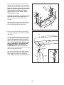
6. Identify the Left Handrail Cover (80) and the
Right Handrail Cover (81). Insert the end of the
Left Handrail (79) through the large hole in the
L
eft Handrail Cover, and insert the end of Right
Handrail (82) through the large hole in the Right
H
andrail Cover.
Attach the Handrail Covers (80, 81) to the
Handrails (79, 82) with two M4.2 x 19mm
Screws (5) in the locations shown.
5
81
H
ole
Hole
5
80
82
79
6
7. Set the Console (94) face down on a soft sur-
face to avoid scratching the Console. Hold the
Right Handrail (82) near the Console as shown.
Insert the console wire into the large hole in the
side of the Right Handrail and out of the hole in
the top as shown.
82
7
Large
Hole
94
Console
Wire

10
8. Attach the Right Handrail (82) to the Console
(94) with an M5 x 16mm Screw (9), an M5 Star
Washer (13), and two M4.2 x 19mm Screws (5).
M
ake sure that no wires are pinched. Start all
three Screws before tightening any of them.
T
ighten the M5 x 16mm Screw and then
tighten the M4.2 x 19mm Screws. Do not
overtighten the Screws.
Attach the Left Handrail (79) to the other side
of the Console (94) in the same way. Note:
There are no wires on the left side of the
Console.
Remove the plastic ties from the Right Handrail
(82) and the Left Handrail (79). If necessary,
press the M8 Cage Nuts (41) into place.
8
9
9
5
94
82
79
13
13
5
5
5
83
9
9. Have a second person hold the Console (94)
near the Right Upright (87) and the Left Upright
(not shown).
Connect the Wire Harness (83) to the console
wire. See the inset drawing. The connectors
should slide together easily and snap into
place. If they do not, turn one connector and try
again. IF THE CONNECTORS ARE NOT CON-
NECTED PROPERLY, THE CONSOLE MAY
BE DAMAGED WHEN THE POWER IS
TURNED ON. Remove the wire tie from the
Wire Harness. Insert the connectors and excess
wire into the Right Upright (87).
Next, insert the brackets on the Right Handrail
(82) and the Left Handrail (not shown) into the
Right Upright (87) and the Left Upright (not
shown). Make sure that no wires are pinched.
87
83
Console
Wire
94
41
41
Wire
Tie
Console
Wire
82

11
10. Attach the Console (94) to the Uprights (86, 87)
with six M8 x 16mm Bolts (3) and six 5/16" Star
Washers (14). Start all six Bolts before tight-
ening any of them.
1
0
14
3
3
3
14
14
14
86
87
11. With the help of a second person, lower the
Uprights (86, 87) as shown.
See the lower drawing. Position the Uprights
(86, 87) so that the Frame (61) is centered be-
tween the Uprights.
Firmly tighten the M10 x 58mm Bolts (2) and the
M10 x 110mm Bolt (1) on each side of the tread-
mill (only one is shown). Do not overtighten
the M10 x 110mm Bolts.
87
86, 87
1
61
61
86
View from Above
Side View
11
2
94
3

12
15. Make sure that all parts are properly tightened before you use the treadmill. Keep the included hex keys
in a secure place. The large hex key is used to adjust the walking belt (see page 21). To protect the floor or
carpet, place a mat under the treadmill.
12. Attach the Latch Housing (85) to the Left Upright
(86) with two #10 x 1" Tek Screws (7). Make
sure that the Latch Housing is oriented as
shown.
Locate the Latch Pin Assembly (84). Remove
the knob from the pin. Make sure that the collar
and the spring are on the pin as shown. Insert
t
he pin into the Latch Housing (85), and tighten
the knob back onto the pin.
13. Attach each Incline Leg (63) to the Frame (61)
with an M8 x 52mm Bolt (8), two M8 Washers
(10), and an M8 Nut (16).
13
61
14. Insert the Incline Pins (62) at the desired incline
level (see HOW TO CHANGE THE INCLINE OF
THE TREADMILL on page 17
).
14
8
10
63
10
16
10
10
8
62
62
7
Pin
Spring
Collar
Knob
85
86
Large Hole
1
2
63
84

13
OPERATION AND ADJUSTMENT
T
HE PRE-LUBRICATED WALKING BELT
Your treadmill features a walking belt coated with high-
performance lubricant. IMPORTANT: Never apply sil-
i
cone spray or other substances to the walking
belt or the walking platform. Such substances will
deteriorate the walking belt and cause excessive
wear.
HOW TO PLUG IN THE POWER CORD
Your treadmill, like any other type of sophisticated
electronic equipment, can be seriously damaged by
sudden voltage changes in your homeʼs power.
Voltage surges, spikes, and noise interference can
result from weather conditions or from other appli-
ances being turned on or off. To decrease the possi-
bility of your treadmill being damaged, always
use a surge suppressor with your treadmill (see
drawing 1 at the right). To purchase a surge sup-
pressor, see your local WESLO dealer or call the
telephone number on the front cover of this man-
ual and order part number 146148, or see your local
electronics store.
Use only a single-outlet surge suppressor that is
UL 1449 listed as a transient voltage surge sup-
pressor (TVSS). The surge suppressor must have a
UL suppressed voltage rating of 400 volts or less
and a minimum surge dissipation of 450 joules.
The surge suppressor must be electrically rated for
120 volts AC and 15 amps. There must be a moni-
toring light on the surge suppressor to indicate
whether it is functioning properly. Failure to use a
properly functioning surge suppressor could result
in damage to the control system of the treadmill. If
the control system is damaged, the walking belt
may change speed, accelerate or stop unexpect-
edly, which may result in a fall and serious injury.
This product must be grounded. If it should malfunc-
tion or break down, grounding provides a path of least
resistance for electric current to reduce the risk of elec-
t
ric shock. This product is equipped with a cord having
an equipment-grounding conductor and a grounding
plug. Plug the power cord into a surge suppressor,
and plug the surge suppressor into an appropriate
o
utlet that is properly installed and grounded in
accordance with all local codes and ordinances.
IMPORTANT: The treadmill is not compatible with
GFCI-equipped outlets.
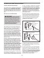
This product is for use on a nominal 120-volt circuit,
and has a grounding plug that looks like the plug illus-
trated in drawing 1 below. A temporary adapter that
looks like the adapter illustrated in drawing 2 may be
used to connect the surge suppressor to a 2-pole
receptacle as shown in drawing 2 if a properly
grounded outlet is not available.
The temporary adapter should be used only until a
properly grounded outlet (drawing 1) can be installed
by a qualified electrician.
The green-colored rigid ear, lug, or the like extending
from the adapter must be connected to a permanent
ground such as a properly grounded outlet box cover.
Whenever the adapter is used it must be held in place
by a metal screw. Some 2-pole receptacle outlet box
covers are not grounded. Contact a qualified elec-
trician to determine if the outlet box cover is
grounded before using an adapter.
DANGER: Improper connection
of the equipment-grounding conductor can
result in an increased risk of electric shock.
Check with a qualified electrician or service-
man if you are in doubt as to whether the
product is properly grounded. Do not modify
the plug provided with the product—if it will
not fit the outlet, have a proper outlet
installed by a qualified electrician.
1
2
Grounded Outlet Box
Grounded Outlet Box
Grounding Plug
Surge Suppressor
Surge Suppressor
Grounding Pin
Adapter
Lug
Metal Screw
Grounded Outlet
Grounding Pin

14
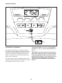
FEATURES OF THE CONSOLE
The treadmill console offers a selection of features
designed to make your workouts more effective. When
you select the manual mode of the console, you can
change the speed of the treadmill with the touch of a
button. As you exercise, the console will display con-
tinuous exercise feedback.
The console also features four speed workouts. Each
program controls the speed of the treadmill as it guides
you through an effective exercise session.
To turn on the power, see page 15. To use the man-
ual mode, see page 15. To use a speed workout, see
page 17.
IMPORTANT: If there are sheets of clear plastic on
the console, remove the plastic. To prevent damage
to the walking platform, wear clean athletic shoes
while using the treadmill. The first time you use the
treadmill, observe the alignment of the walking
belt, and center the walking belt if necessary (see
page 21).
Key
Clip
CONSOLE DIAGRAM

15
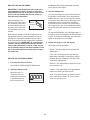
HOW TO TURN ON THE POWER
IMPORTANT: If the treadmill has been exposed to
c
old temperatures, allow it to warm to room tem-
perature before turning on the power. If you do not
d
o this, you may damage the console display or
other electrical components.
Plug in the power cord
(see page 13). Next, locate
the reset/off circuit breaker
on the treadmill frame near
the power cord. Switch the
circuit breaker to the reset
position.
Next, stand on the foot rails of the treadmill. Find the
clip attached to the key (see the drawing on page 14)
and slide the clip onto the waistband of your clothes.
Then, insert the key into the console. After a moment,
the display will light. IMPORTANT: In an emergency
situation, the key can be pulled from the console,
causing the walking belt to slow to a stop. Test the
clip by carefully taking a few steps backward; if the
key is not pulled from the console, adjust the posi-
tion of the clip.
HOW TO USE THE MANUAL MODE
1. Insert the key into the console.
See HOW TO TURN ON THE POWER above.
2. Select the manual mode.
When the key is in-
serted, the manual
mode will be selected. If
a speed workout has
been selected, press
the Workout Select button repeatedly until only
zeros appear in the display.
3
. Start the walking belt.
T
o start the walking belt, press the Start button or
the Speed increase button. The walking belt will
begin to move at 1 mph. As you exercise, change
the speed of the walking belt as desired by press-
ing the Speed increase and decrease buttons.
Each time you press a button, the speed setting
will change by 0.1 mph; if you hold down a button,
the speed setting will change in increments of 0.5
mph.
To stop the walking belt, press the Stop button. If
the time is shown in the display, the time will begin
to flash. To restart the walking belt, press the Start
button or the Speed increase button.
4. Follow your progress with the display.
The display features five modes:
• Speed—This mode displays the speed of the
walking belt.
• Time—This mode displays the elapsed time.
Note: When a workout is selected, the display
will show the time remaining in the workout in-
stead of the elapsed time.
• Distance—This mode displays the distance you
have walked or run.
• Calories—This mode displays the approximate
number of calories you have burned.
• Scan—This mode displays the speed, time, dis-
tance, and calories modes, for a few seconds
each, in a repeating cycle.
Reset
Position

16
Each time the key is in-
serted into the console,
the Scan mode will be
s
elected. The SCAN
mode indicator will ap-
p
ear in the display, and
a second mode indicator will show which mode is
currently displayed. Note: If you have selected a
different mode, repeatedly press the Display Mode
button to reselect the scan mode.
To select the Speed,
Time, Distance, or
Calories mode for con-
tinuous display, repeat-
edly press the Display
Mode button. The mode
indicators will show which mode is selected. Make
sure that the SCAN mode indicator does not ap-
pear.
To reset the display, press the Stop button, remove
the key, and then reinsert the key.
The console can display speed and distance in ei-
ther miles or kilometers (MPH or Km/H will appear
when the Speed mode is
displayed). To change
the unit of measurement,
r
emove the key, hold
down the Stop button
w
hile inserting the key
into the console, and then release the Stop button.
An “E” for English miles or an “M” for metric kilome-
ters will appear in the display. Press the Speed in-
crease button to change the unit of measurement.
Then, remove the key and reinsert it.
5. When you are finished exercising, remove the
key from the console.
Step onto the foot rails, press the Stop button, re-
move the key from the console, and put it in a secure
place.
When you are finished using the treadmill, switch
the reset/off circuit breaker to the “off” position and
unplug the power cord. IMPORTANT: If you do
not do this, the treadmillʼs electrical compo-
nents may wear prematurely.

17
HOW TO USE A SPEED WORKOUT
1. Insert the key into the console.
See HOW TO TURN ON THE POWER on page 15.
2. Select a speed workout.
To select one of the four
speed workouts, press
the Workout Select but-
ton repeatedly until the
number of the desired
workout appears in the
display. The duration of the workout will then ap-
pear in the display. The profiles below the display
show how the speed of the walking belt will change
during the workouts.
3. Select the duration of the workout if desired.
You can set the duration of the workout to a time
between 15 and 45 minutes, in increments of 5
minutes. To set the duration of the workout press
the Time increase or decrease button until the de-
sired time is selected.
4. Press the Start button or the Speed increase
button to start the workout.
A moment after you press the button, the treadmill
will automatically adjust to the first speed and in-
cline settings of the workout. Hold the handrails
and begin walking.
Each workout is divided into 30 one-minute seg-
ments, unless you have changed the duration of
the workout (see step 3). One speed setting is pro-
grammed for each segment. The same speed set-
ting may be programmed for consecutive segments.
At the end of each segment of the workout, a se-
ries of tones will sound. If a different speed setting
is programmed for the next segment, the speed
setting will flash in the display to alert you. When
the next segment begins, the speed of the walking
belt will automatically adjust to the speed setting
for the next segment.
The workout will continue in this way until the last
segment of the workout ends. The walking belt will
then slow to a stop.
If the speed setting for the current segment is too
high or too low, you can manually override the set-
ting by pressing the Speed buttons; however,
when the next segment begins, the treadmill
will automatically adjust to the speed setting
f
or the next segment.
T
o stop the workout temporarily, press the Stop
button. If the time is shown in the display, the time
will begin to flash. To restart the workout, press the
Start button or the Speed increase button. The
walking belt will begin to move at 1 mph. When the
next segment of the workout begins, the treadmill
will automatically adjust to the speed setting for the
next segment.
5. Follow your progress with the display.
See step 4 on pages 15 and 16.
6. When you are finished exercising, remove the
key from the console.
See step 5 on page 16.
HOW TO CHANGE THE INCLINE OF THE TREADMILL
To vary the intensity of your exercise, you can change
the incline of the treadmill. There are three incline lev-
els. Before changing the incline, remove the key
and unplug the power cord. Next, fold the treadmill
to the storage position (see page 18).
To change the incline, first remove the incline pin from
one of the incline legs. Adjust the incline leg to the de-
sired position, and then fully reinsert the incline pin.
Adjust the other incline leg in the same way. CAUTION:
Before using the treadmill, make sure that both in-
cline legs are at the same height and that both in-
cline pins are fully inserted into the incline legs.
After you have adjusted the incline legs, lower the
treadmill (see page 19).
Incline
Leg
Incline
Pin
Incline
Pin

18
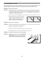
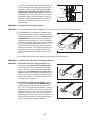
HOW TO FOLD AND MOVE THE TREADMILL
H
OW TO FOLD THE TREADMILL FOR STORAGE
Unplug the power cord. CAUTION: You must be able to
safely lift 45 lbs. (20 kg) to raise, lower, or move the
treadmill.
1. Hold the metal frame firmly in the location shown by
the arrow at the right. CAUTION: To decrease the pos-
sibility of injury, do not lift the frame by the plastic
foot rails. Make sure to bend your legs and keep your
back straight. As you raise the frame, make sure to lift
with your legs rather than your back. Raise the frame
about halfway to the vertical position.
2. Move your right hand to the position shown and hold the
treadmill firmly. Using your left hand, pull the latch knob
to the left and hold it. Raise the frame until the hole in the
latch plate is aligned with the latch pin. Slowly release the
latch knob; make sure that the latch pin is fully in-
serted into the latch plate.
To protect the floor or carpet from damage, place a
mat under the treadmill. Keep the treadmill out of di-
rect sunlight. Do not leave the treadmill in the stor-
age position in temperatures above 85° F (30° C).
HOW TO MOVE THE TREADMILL
Before moving the treadmill, convert the treadmill to the stor-
age position as described above. Make sure that the latch
pin is fully inserted into the latch plate.
1. Hold the handrails and place one foot against a wheel.
2. Tilt the treadmill back until it rolls freely on the wheels.
Carefully move the treadmill to the desired location. Never
move the treadmill without tipping it back. To reduce
the risk of injury, use extreme caution while moving
the treadmill. Do not attempt to move the treadmill
over an uneven surface.
3. Place one foot against one of the wheels, and carefully
lower the treadmill until it is in the storage position.
1
Frame
Handrail
Wheel
Latch Pin
Latch Knob
Latch
Plate
2

19
HOW TO LOWER THE TREADMILL FOR USE
1
. Hold the treadmill with your right hand as shown. Pull the
latch knob to the left and hold it. Pivot the frame down
until it is past the latch pin. Slowly release the latch knob.
2. Hold the metal frame firmly with both hands, and lower
it to the floor. CAUTION: To decrease the possibility of
injury, do not lower the frame by gripping only the
plastic foot rails. Do not drop the frame to the floor.
Make sure to bend your legs and keep your back
straight.
Frame
Latch
Pin
Latch
Knob
1
2

20
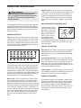
TROUBLESHOOTING
M
ost treadmill problems can be solved by following the steps below. Find the symptom that applies, and
follow the steps listed. If further assistance is needed, please see the front cover of this manual.
PROBLEM: The power does not turn on
SOLUTION: a. Make sure that the power cord is plugged into a surge suppressor, and that the surge suppressor
is plugged into a properly grounded outlet (see page 13). Use only a single-outlet surge suppres-
sor that meets all of the specifications described on page 13. IMPORTANT: The treadmill is not
compatible with GFCI-equipped outlets.
b. After the power cord has been plugged in, make sure that the key is fully inserted into the console.
c. Check the reset/off circuit breaker located on the
treadmill frame near the power cord. If the switch
protrudes as shown, the circuit breaker has
tripped. To reset the circuit breaker, wait for five
minutes, and then press the switch back in.
PROBLEM: The power turns off during use
SOLUTION: a. Check the reset/off circuit breaker (see the drawing above). If the circuit breaker has tripped, wait
for five minutes and then press the switch back in.
b. Make sure that the power cord is plugged in.
c. Remove the key from the console. Reinsert the key fully into the console.
d. If the treadmill still will not run, please see the front cover of this manual.
PROBLEM: The displays of the console do not function properly
SOLUTION: a. Remove the key from the console and UNPLUG THE
POWER CORD. Remove the three indicated M4.2 x
19mm Hood Screws (21) and the two M5.5 x 25mm
Screws (24). Carefully remove the Motor Hood (68).
Tripped
Position
Reset
Position
c
24
21
68
a
Page is loading ...
Page is loading ...
Page is loading ...
Page is loading ...
Page is loading ...
Page is loading ...
Page is loading ...
Page is loading ...
-
 1
1
-
 2
2
-
 3
3
-
 4
4
-
 5
5
-
 6
6
-
 7
7
-
 8
8
-
 9
9
-
 10
10
-
 11
11
-
 12
12
-
 13
13
-
 14
14
-
 15
15
-
 16
16
-
 17
17
-
 18
18
-
 19
19
-
 20
20
-
 21
21
-
 22
22
-
 23
23
-
 24
24
-
 25
25
-
 26
26
-
 27
27
-
 28
28


Ask a question and I''ll find the answer in the document
Finding information in a document is now easier with AI
Related papers
Other documents
-
ProForm 380 CS User manual
-
Pro-Form PFTL39511.0 User manual
-
-
Pro-Form 831248531 User manual
-
-
-
-
-
ProForm PETL40807 Owner's manual
-