Honeywell Thermostat T8112D User manual
- Category
- Thermostats
- Type
- User manual
This manual is also suitable for
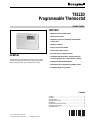
Honeywell Thermostat T8112D is an energy-saving programmable thermostat for single-stage heating and cooling applications. It features precise temperature control thanks to self-calibrating thermostat and thermometer accurate to within ±1.25°F. With a large LCD display and intuitive programming, it's easy to set up and monitor. Choose from four daily energy-saving programs and adjust heating cycles to 3, 6, or 9 cycles per hour. The thermostat is compatible with most 24 Vac standing pilot, gas electronic ignition, oil or central electric systems.
Honeywell Thermostat T8112D is an energy-saving programmable thermostat for single-stage heating and cooling applications. It features precise temperature control thanks to self-calibrating thermostat and thermometer accurate to within ±1.25°F. With a large LCD display and intuitive programming, it's easy to set up and monitor. Choose from four daily energy-saving programs and adjust heating cycles to 3, 6, or 9 cycles per hour. The thermostat is compatible with most 24 Vac standing pilot, gas electronic ignition, oil or central electric systems.


-
 1
1
-
 2
2
-
 3
3
-
 4
4
-
 5
5
-
 6
6
-
 7
7
-
 8
8


Honeywell Thermostat T8112D User manual
- Category
- Thermostats
- Type
- User manual
- This manual is also suitable for
Honeywell Thermostat T8112D is an energy-saving programmable thermostat for single-stage heating and cooling applications. It features precise temperature control thanks to self-calibrating thermostat and thermometer accurate to within ±1.25°F. With a large LCD display and intuitive programming, it's easy to set up and monitor. Choose from four daily energy-saving programs and adjust heating cycles to 3, 6, or 9 cycles per hour. The thermostat is compatible with most 24 Vac standing pilot, gas electronic ignition, oil or central electric systems.
Ask a question and I''ll find the answer in the document
Finding information in a document is now easier with AI
Related papers
-
Honeywell Honeywell/20 CT2095 User manual
-
Honeywell CT2800 Owner's manual
-
Honeywell T8400C User manual
-
-
-
Honeywell Honeywell/34 CT3455 User manual
-
-
-
Honeywell Electronic User manual
-