Lennox Merit 14HPX-024 Installation Instructions Manual

Category
Split-system air conditioners
Type
Installation Instructions Manual
,1_2008 Lennox Industries Inc,
Dallas, Texas, USA
INSTALLATION
INSTRUCTIONS
14HPX Series Units
HEAT PUMP UNITS _Technical
505,243M LLJJ Publications
04108 Litho U.S.A.
Supersedes 03/08
RETAIN THESE INSTRUCTIONS
FOR FUTURE REFERENCE
WARNING
CAUTION
14HPX Outdoor Unit ........................... 1
Shipping and Packing List ...................... 1
Unit Dimensions ............................... 2
General Information ........................... 3
Setting the Unit ............................... 3
Electrical ..................................... 4
Refrigerant Piping ............................. 5
Flushing Existing Line Set and Indoor Coil ........ 8
Refrigerant Metering Device .................... 9
Manifold Gauge Set ........................... 10
Service Valves ................................ 10
Leak Testing .................................. 11
Evacuation ................................... 11
Start-Up ...................................... 12
Refrigerant Charge ............................ 12
Checking Indoor Airflow ....................... 12
Setup for Checking and Adding Charge .......... 13
System Operation ............................. 17
Defrost System ............................... 17
Maintenance .................................. 22
Optional Accessories .......................... 23
Homeowner Information ........................ 23
Thermostat Operation .......................... 24
14HPX Check List ............................. 24
IMPORTANT
IMPORTANT
14HPX Merit ® outdoor units use HFC-410A refrigerant.
This unit must be installed with a matching indoor blower
coil and line set as outlined in the Lennox Engineering
Handbook. 14HPX outdoor units are designed for use in
expansion valve systems only. They are not designed to be
used with other refrigerant flow control devices. An expan-
sion valve approved for use with HFC-410A must be or-
dered separately and must be installed prior to operating
the unit.
1-Assembled 14HPX outdoor unit
Check the unit components for shipping damage. If you
find any damage, immediately contact the last carrier.
04/08
[[IHHI[III[IIIHIlII[IIIII[[IH[III Page 1 505,243M
[III[I[[IIII[I[[I[I[IIIIIII[IIHI[[III
INLET AIR
,_ INLET AIR
©
INLET AIR
iT_
4-3/8
(111)
T
OPTIONAL UNIT STAND-OFF KIT
(4) (FIELD-INSTALLED)
COIL DRAIN OUTLETS ir
(AROUND PERIMETER OF
BASE)
5-3/8
VAPOR LINE CONNECTION (152)
INLET AIR,,_i_ LIQUID LINE CONNECTION "_
TOP VIEW TOP VIEW BASE SECTION
A _--J
,91--- A_' OUTDOOR COIL FAN tD SCHARGE A R
4-3/8
(111)
4-3/8
(111)
COMPRESSOR
VAPOR AND LIQUID
LINE CONNECTIONS
2-3/4 (70)
OPTIONAL UNIT
STAND-OFF KIT (4)
(FIELDqNSTALLED)
m
SIDE VIEW 3/4(19) _i SIDE VIEW
Model No. ABC
14HPX-018 24-1/4 (616) 29-1/4 (743) 28-1/2 (724)
14HPX-024 24-1/4 (616) 29-1/4 (743) 28-1/2 (724)
14HPX-030 24-1/4 (616) 33-1/4 (845) 32-1/2 (826)
14HPX-036 32-1/4 (819) 29-1/4 (743) 28-1/2 (724)
14HPX-042 32-1/4 (819) 37-1/4 (946) 36-1/2 (927)
14HPX-048 32-1/4 (819) 37-1/4 (946) 36-1/2 (927)
14HPX-060 32-1/4 (819) 43-1/4 (1099) 42-1/4 (1073)
505243 04/08
Page 2
WhenservicingorrepairingHVACcomponents,ensure
capsandfastenersareappropriatelytightened.Table1
liststorquevaluesfortypicalservice/repairitems,
Table1.TorqueRequirements
Part Recommended Torque
Liquid service valve cap 85 in.-lb. 10 NM
Suction service valve cap 85 in.-lb. 10 NM
Sheet metalscrews 16 in.-lb. 2 NM
Machine screws #8 28 in.-lb. 3 NM
Compressor bolts 90 in.-lb. 10 NM
Gauge port seal cap 62 in.-lb. 7 NM
These instructions are intended as a general guide and do
not supersede national or local codes in any way. Consult
authorities having jurisdiction before installation,
WARNING
CAUTION
1, Place a sound-absorbing material, such as Isomode,
under the unit if it will be installed in a location or posi-
tion that will transmit sound or vibration to the living
area or adjacent buildings+
2, Mount unit high enough above ground or roof to allow
adequate drainage of defrost water and prevent ice
build-up,
3. In heavy snow areas, do not locate unit where drifting
will occur, The unit base should be elevated above the
depth of average snows.
NOTE -Elevation of the unit may be accomplished by
constructing a frame using suitable materials. If a sup-
port frame is constructed, it must not block drain holes
in unit base.
4. When installed in areas where low ambient tempera-
tures exist, locate unit so winter prevailing winds do
not blow directly into outdoor coil.
5. Locate unit away from overhanging roof lines which
would allow water or ice to drop on, or in front of, coil
or into unit.
(AS NOTED)
*A service clearance of 30" (702 mm) must be maintained on one
of the sides adjacent to the control box+Clearance to one of the
other three sides must be 36" (914 mm), Clearance to one of the
remaining two sides may be 12" (305 mm) and the final side may
be 6" (152 mm).
A clearance of 24" (610 mm) must be maintained between two
units. 48" (1219 mm) clearance required on top of unit+ Maximum
soffit overhang is 36" (914 mm).
Figure 1. Installation Clearances
SLAB MOUNTING
When installing the unit at grade level, the top of the slab
should be high enough above the grade so that water from
higher ground will not collect around the unit. See figure 2.
The slab should have a slope tolerance away from the
building of 2 degrees or 2 inches per 5 feet (51 mm per
1524 mm). This will prevent ice build-up under the unit dur-
ing a defrost cycle. Refer to roof mounting section for barri-
er construction if the unit must face prevailing winter winds,
Unit is shown with optional stand-offs (Cat# 94J35),
DISCHARGE AIR
STRUCTURE 0
OPTIONAL
STAND-OFFS
(CAT#94J35)
MOUNTING SLAB MUST SLOPE GROUND
AWAY FROM BUILDING. LEVEL
Figure 2. Slab Mounting At Ground Level
Page 3
14HPX SERIES
ROOF MOUNTING
Install unit a minimum of 6 inches (152 mm) above the roof
surface to avoid ice build-up around the unit Locate the
unit above a load bearing wall or area of the roof that can
adequately support the unit Consult local codes for roof-
top applications
PREVAILING WINTER WINDS
©
I WINDBARRIER I
INLET AIR
0
INLET AIR
0
0
INLET AIR
INLET AIR
0
Figure 3. Rooftop Application Wind Barrier
If unit coil cannot be mounted away from prevailing winter
winds, construct a wind barrier Size barrier at least the
same height and width as the outdoor unit Mount barrier
24 inches (610 mm) from the sides of the unit in the direc-
tion of prevailing winds
In the USA. wiring must conform with current local codes
and the current National Electric Code (NEC) In Canada,
wiring must conform with current local codes and the current
Canadian Electrical Code (CEC)
WARNING I
Refer to the furnace or blower coil installation instructions
for additional wiring application diagrams and refer to unit
nameplate for minimum circuit ampacity and maximum
overcurrent protection size
1 Install line voltage power supply to unit from a properly
sized disconnect switch (see figure 6)
2 Ground unit at unit disconnect switch or to an earth
ground (see figure 6)
,
,
NOTE -Tofacilitate conduit, a hole is in the bottom of
the control box. Connect conduit to the control box
using a proper conduit fitting.
NOTE -Units are approved for use only with copper
conductors. 24V, Class II circuit connections are
made in the low voltage junction box. Refer to figure 6
for field wiring diagram.
NOTE -A complete unit wiring diagram is located in-
side the unit control box cover.
NOTE -For proper voltages, select thermostat wire
gauge per the following chart:
Wire run length AWG # Insulation type
less than 100' (30m) 18 color-coded, temperature
more than 100' (30m) 16 rating 35°C minimum
Install room thermostat (ordered separately) on an in-
side wall approximately in the center of the conditioned
area and 5 feet (1.5 m) from the floor. It should not be
installed on an outside wall or where it can be effected
by sunlight, drafts or vibrations.
Install low voltage wiring from outdoor to indoor unit
and from thermostat to indoor unit (see figures 4 & 5).
NOTE -24V, Class II circuit connections are made in
the low voltage junction box.
Thermostat Outdoor Unit
®1 ®
power
common
1st, stage aux heat
indoor blower
reversing valve
Indoor Unit
q_(_ power
_(__ common
iI_ 1st. stage aux. heat
4-@- ,
compressor
(SOME CONNECTIONS MAY NOT APPLY. REFER
TO SPECIFIC THERMOSTAT AND INDOOR UNIT.)
Figure 4. Outdoor Unit/Blower Unit Field Wiring
Indoor UnitThermostat
(R) -- -po-weL - - -_
oommonj
k.C/
(_ emergency h%at __
I
I
@
®
®
@
- _sLst_e Su£_FI l-
k
indoor btower
reversing valve
compressor
(SOME CONNECTIONS MAY NOT APPLY. REFER TO
SPECIFIC THERMOSTAT AND INDOOR UNIT.)
Outdoor Unit
,_ power (_1
oommon@1
emer
heay_"_/_e_
@1
-®1 ®1
@1
Figure 5. Outdoor Unit/Blower Unit Field Wiring
(with outdoor thermostat and emergency heat relay)
505243 04/08
Page 4
Z_ NOTE-
FOR USE WITH COPPER CONDUCTORS
ONLY.REFER TO UNIT RATIN6
PLATE FOR MINIMUM CIRCUIT
ANPACITY AND MAXIMUM OVER-
CURRENT PROTECTION SIZE
Z_ REFER TO COMPRESSOR IN UNIT
FOR ACTUAL TERMINAL ARRANGEMENT.
/_ WARNING-
ELECTRIC SHOCK HAZARD,CAN CAUSE INJURY
OR DEATH.UNIT MUST BE GREED IN
ACCO_OANCE WITH NATIONAL AND LOCAL CODES.
RTI4 SENSOR, OUTDOOR TEMP (OPTIONAL)
£,87 LOV! LI
PRESSURE REVERSIND
SWITCH VALVE
C_WPBESSO_
CORTACTOR
EQUIPMENT
6ROUND
COMPRESSOR
CONTACTOR
L2_ )--C)
S,€
HI6H
PRESSURE
SWITCH
Q
RTI5
AMBIENT
SENSOR
0
RT2 I
DEFROST
COIL
SENSOR
@
CI2
CAPACITOR
O OUT
AI_
DEFROST CONTROL ;OIL
_MB
)IS
OUT
OPS
2 OUT
KI
COMPRESSOR
CONTACTOR
c
c
c
c
c
c
C
CBSIMV
-'_91_- I-----
--0-1---- --
-
SIGNATURE
81M2B
TWlSTEO
RTI4
m'
GROUNDz_
208-
mL2 230/
60/_
L}
_GENDTES OPTIONAL COMPONENTS
_LINE VOLTAGE FIELD INSTALLED
-- -- --CLASS II VOLTAGE FIELD INSTALLED
Figure 6. Typical Field Wiring Diagram
Table 2. Refrigerant Line Sets
If the 14HPX unit is being installed with a new indoor coil
and line set, plumbing connections should be made as out-
lined in this section. If an existing line set and/or indoor coil
is going to be used to complete the 14HPX system, refer to
the following section that includes flushing procedures.
Field refrigerant piping consists of liquid and vapor lines
from the outdoor unit (sweat connections) to the indoor coil
(flare or sweat connections).
Use Lennox L15 (sweat, non-flare) series line sets as
shown in table 2 or use field4abricated refrigerant lines.
Refer to Refrigerant Piping Guide (Corp. 9351-L9) for
proper size, type, and application of field4abricated lines.
Valve sizes are also listed in table 2.
PLUMBING CONNECTIONS--14HPX MATCHED
WITH NEW INDOOR COIL AND LINE SET
If replacing an existing coil that is equipped with a liquid line
functioning as a metering orifice, replace the liquid line
prior to installing the 14HPX unit. See table 2.
Field
Mod- Connections
el Liquid Vapor
Line Line
-018 3/8in. 3/4in
-024 (10 mm) (19 mm)
-030
-036 3/8 in. 7/8 in
-042 (10 ram) (22 ram)
-048
-060 3/8 in. 1-1/8 in,
(10 mm) (29 mm)
Recommended Line Set
Liquid Vapor L15
Line Line Line Sets
3/8 in. 3/4 in L15-41
(10mm) (19mm) 15 ft. - 50 ft.
(4.6 m - 15 m)
3/8 in, 7/8 in L15-65
(10mm) (22mm) 15 ft, - 50 ft.
(4.6 m- 15 m)
3/8 in. 1-1/8 in, Field
(10 mm) (29 mm) Fabricated
NOTE -Units are designed for line sets of up to fifty feet (15
m); for longer lengths, consult the Lennox Refrigerant Pip-
ing Guide (Corp. 9351-L9). Select line set diameters from
table 2to ensure that oil returns to the compressor.
Page 5
14HPX SERIES
INSTALLING REFRIGERANT LINE
Pay close attention to line set isolation during installation of
any heat pump or a/c system. When properly isolated from
building structures (walls, ceilings, floors), the refrigerant
lines will not create unnecessary vibration and subsequent
noises. Also, consider the following when placing and
installing a high-efficiency outdoor unit:
1, Placement--Some localities are adopting sound ordi-
nances based on the unit's noise level observed from
the adjacent property, not from the installation proper-
ty. Install the unit as far as possible from the property
line. When possible, do not install the unit directly out-
side a window, Glass has a very high level of sound
transmission. Figure 7 shows how to place the outdoor
unit and line set.
2, Line Set Isolation--The following illustrations dem-
onstrate procedures which ensure proper refrigerant
line set isolation, Figure 8 shows how to install line sets
on vertical runs. Figure 9 shows how to make a transi-
tion from horizontal to vertical. Figure 10 shows how
to install line sets on horizontal runs,
Install unit away
from windows.
Two 90° elb_
installed in line set will
• reduce line set vibration.
Figure 7. Unit Placement and Installation
NOTE -Similar instaflation practices should be used it line set Is to be Installed on exterior ot outside wall.
OUTSIDE WALL IMPORTANT - Refrigerant
lines must not contact wall. VAPOR LINE LI UID LINE
IMPORTANT!
Refrigerant
lines must
not contact
structure,
VAPOR LINE WRAPPED
WITH ARMAFLEX LIt?NIED
iiiiiiiiiiiiiiiiiiiiiiiiiiiiiiiiiiiiiiiiiiiiiiiiiiiiiiiiiiiiiiiiiiiiiiiiiiiiiiiiiiiiiiiiiiiiiiiiiiiiiiiiiiiiiiii_!
CAULK
PVC PIPE FIBERGLASS
INSULATION
WIRE TIE
s INSlDEWALL
STRAP
SLEEVE
WIRE TIE
WOOD BLOCK
WIRE TIE
STRAP
SLEEVE
Figure 8. Refrigerant Line Sets: Installing Vertical Runs (new construction shown
505243 04/08
Page 6
ANCHORED
HEAVY NYLON
WIRE TIE
AUTOMOTIVE
MUFFLER-TYPE
HANGER
WALL
STUD WALL
STUD
Strap Liquid
Line To Va- Strap Liquid Line
por Line To Vapor Line
)UID LINE LIQUID LINE
METAL VAPOR LINE - WRAPPED METAL VAPOR LINE - WRAPPED
SLEEVE IN ARMAFLEX SLEEVE IN ARMAFLEX
Figure 9. Refrigerant Line Sets: Transition From Vertical To Horizontal
To hang line set from joist or rafter,
use either metal strapping material
or anchored heavy nylon wire ties. 8 feet
WIRE TIE
(Around vapor line only)
STRAPPING MATERIAL
(Around vapor line only)
feet
METAL FLOOR JOIST OR
SLEEVE ROOF RAFTER
TAPE OR WIRE TIE H
\TAPE OR WIRE TIE
Strap the vapor line to the joist or
rafter at 8 ft, intervals then strap
the liquid line to the vapor line.
Figure 10. Refrigerant Line Sets: Installing Horizontal Runs
WARNING
BRAZING CONNECTION PROCEDURE
1. Cut ends of the refrigerant lines square (free from
nicks or dents). Debur the ends. The pipe must remain
round, do not pinch end of the line.
2. Flow dry nitrogen through the refrigerant piping while
making line set connections; this prevents carbon de-
posits (oxidation) buildup on the inside of the joints be-
ing brazed. Such buildup may restrict refrigerant flow
through screens and metering devices. To do this:
.
.
Flow_ulated nitrogen (at 1 to 2 psig) through the
refrigeration gauge set into the Schrader port con-
nection on the vapor service valve and out of the
Schrader port connection on the liquid service
valve. (Metering device [TXV and RFC] will allow
low pressure nitrogen to flow through the system.)
While nitrogen is flowing, braze refrigerant line set
to the indoor and outdoor units. IMPORTANT: The
flow of nitrogen must have an escape path
other than through the joint to be brazed.
Use silver alloy brazing rods (5 or 6 percent minimum
silver alloy for copper-to-copper brazing or 45 percent
silver alloy for copper-to-brass or copper-to-steel
brazing) which are rated for use with HFC-410A refrig-
erant.
Wrap a wet cloth around the valve body and copper
tube stub to protect it from heat damage during braz-
ing. Wrap another wet cloth underneath the valve body
to protect the base paint.
Page 7
14HPX SERIES
NOTE -The tube end must stay bottomed in the fitting
during final assembly to ensure proper seating, seal-
ing and rigidity.
5, Install a field-provided thermal expansion valve (ap-
proved for use with HFC-410A refrigerant) in the liquid
line at the indoor coil,
,A WARNING I
IMPORTANT
Connect to the existing unit, a clean recovery cyl-
inder and the recovery machine according to the
instructions provided with the recovery machine.
Remove all HCFC-22 refrigerant from the existing
system. Check gauges after shutdown to confirm
that the entire system is completely void of refrig-
erant.
Disconnect the liquid and vapor lines from the ex-
isting outdoor unit.
If the existing outdoor unit is equipped with
manual shut-off valves AND you plan to use NEW
HCFC-22 refrigerant to flush the system -
Start the existing HCFC-22 system in the cooling
mode and close the liquid line valve.
Pump all of the existing HCFC-22 refrigerant back
into the outdoor unit. (it may be necessary to by-
pass the low pressure switches to ensure com-
plete refrigerant evacuation,)
When the low side system pressures reach 0 psig,
close the vapor line valve.
Disconnect all power to the existing outdoor unit.
Check gauges after shutdown to confirm that the
valves are not allowing refrigerant to flow back into
the low side of the system,
Disconnect the liquid and vapor lines from the ex-
isting outdoor unit.
2, Remove the existing outdoor unit. Set the new
HFC-410A unit and follow the brazing connection pro-
cedure (see page 7) to make line set connections.
DO NOT install metering device at this time.
3, Make low voltage and line voltage connections to the
new outdoor unit. DO NOT turn on power to the unit
or open outdoor unit service valves at this time.
IMPORTANT
CAUTION
REQUIRED EQUIPMENT
You will need the following equipment in order to flush the
existing line set and indoor coil: two clean HCFC-22 recov-
ery bottles, an oilless recovery machine with a pump down
feature, and two sets of gauges (one for use with HCFC-22
and one for use with the HFC-410A),
FLUSHING PROCEDURE
1, Remove existing HCFC-22 refrigerant using the ap-
propriate procedure below,
If the existing outdoor unit is not equipped with
shut-off valves, or if the unit is not operational
AND you plan to use the existing HCFC-22 refrig-
erant to flush the system -
Disconnect all power to the existing outdoor unit,
505243 04/08
Page 8
4, Remove the existing refrigerant flow control orifice or
thermal expansion/check valve before continuing with
flushing procedures. The existing devices are not ap-
proved for use with HFC-410A refrigerant and may
prevent proper flushing, Use a field-provided fitting to
reconnect the lines.
5, Remove the pressure tap valve cores from the 14HPX
unit's service valves. Connect an HCFC-22 cylinder
with clean refrigerant to the vapor service valve. Con-
nect the HCFC-22 gauge set to the liquid line valve and
connect a recovery machine with an empty recovery
tank to the gauge set.
6, Set the recovery machine for liquid recovery and start
the recovery machine, Open the gauge set valves to
allow the recovery machine to pull a vacuum on the ex-
isting system line set and indoor coil.
7, Invert the cylinder of clean HCFC-22 and open its
valve to allow liquid refrigerant to flow into the system
through the vapor line valve. Allow the refrigerant to
pass from the cylinder and through the line set and the
indoor coil before it enters the recovery machine,
Inverted HCFC-22 Cylinder
(Contains clean HCFC-22 to be
used for flushing)
RECOVERY CYLINDER
EXISTING VAPOR LINE VAPOR LINE
SERVICE VALVE
EXISTING LIQUID LINE LIQUID LINE
SERVICE VALVE
Tank ReturnInlet
, Discharge
RECOVERY MACHINE
Low High
Pressure Pressure
NOTE - The inverted HCFC-22 cylinder must
contain at least the same amount of refrigerant
as was recovered from the existing system.
Figure 11. Flushing Connections
8. After all of the liquid refrigerant has been recovered,
switch the recovery machine to vapor recovery so that
all of the HCFC-22 vapor is recovered,
NOTE -A single system flush should remove all of the
mineral oil from the existing refrigerant lines and in-
door coil, A second flushing may be done (using clean
refrigerant) if insufficient amounts of mineral oil were
removed during the first flush, Each time the system
is flushed, you must allow the recovery machine
to pull a vacuum on the system at the end of the
procedure.
9. Close the valve on the inverted HCFC-22 drum and
the gauge set valves. Pump the remaining refrigerant
out of the recovery machine and turn the machine off,
10. Use dry nitrogen to break the vacuum on the refriger-
ant lines and indoor coil before removing the recovery
machine, gauges and HCFC-22 refrigerant drum. Re-
install pressure tap valve cores into 14HPX service
valves.
11. Install the provided check/expansion valve (approved
for use with HFC-410A refrigerant) in the liquid line at
the indoor coil.
14HPX units are used in check expansion valve (CTXV)
systems only. See the Lennox Engineering Handbook for
approved valve match-ups and application information,
NOTE -HFC-410A systems will not operate properly with
an HCFC-22 valve.
Check expansion valves equipped with Chatlefffittingsare
available from Lennox. Refer to the Engineering Hand-
book for applicable check expansion valves for use with
specific match-ups, See table 3 for applicable check ex-
pansion valve kits,
Table 3. Indoor Check Expansion Valve Kits
MODEL Kit Number
14HPX-018, -024, -030 49L24
14HPX-036, -042 49L25
14HPX-048, -060 91M02
Page 9
14HPX SERIES
IMPORTANT
If you install a check expansion valve with an indoor coil
that includes a fixed orifice, remove the orifice before the
check expansion valve is installed. See figure 12 for instal-
lation of the check expansion valve,
(Uncased Coil Shown) _.
TWO PIECE |
PATCH PLATE |ORIFICE
(uncased coil ORIFICE IEXPANSI_N VALVE
only) HOUSING I (see note)
TUBES _
ACCESS FITTING
(no valve core)
On smaller suction lines, bulb may be
mounted on top or side-mounled (prefer-
ably at 3 o'clock position).
On 5/8" and larger lines, mount bulb
approximately at the 4 or 8 o'clock posi-
tions; never mount on bottom of line.
9_clock NOTE - If necessary, remove
HCFC-22 flow control device
(fixed orifice/check expansion
valve) from existing line set before
installing HFC-410A approved ex-
pans on va ve and o-r rig,
Figure 12. Metering Device Installation
Manifold gauge sets used with systems charged with
HFC-410A refrigerant must be capable of handling the
higher system operating pressures, The gauges should be
rated for use with pressures d0 - 800 on the high side and
a low side of 30" vacuum to 250 psi with dampened speed
to 500 psi. Gauge hoses must be rated for use at up to 800
psi of pressure with a 4000 psi burst rating,
The service valves (liquid line - figure 13, vapor line - figure
14) and gauge ports are used for leak testing, evacuating,
charging and checking charge, Each valve is equipped
with a service port which has a factory-installed Schrader
valve. A service port cap protects the Schrader valve from
contamination and serves as the primary leak seal.
TO ACCESS SCHRADER PORT:
1, Remove service port cap with an adjustable wrench,
2, Connect gauge to the service port,
3. When testing is completed, replace service port cap and
tighten finger tight; then tighten per table 1 (on page 3),
TO OPEN FRONT-SEATED SERVICE VALVES:
1. Remove stem cap with an adjustable wrench,
2, Use a service wrench with a hex-head extension
(3/16" for liquid-line valve sizes; 5/16" for vapor-line
valve sizes) toback the stem out counterclockwise as
far as it will go,
3. Replace the stem cap. Tighten finger tight; then tighten
per table 1 (on page 3).
TO CLOSE FRONT-SEATED SERVICE VALVES:
1. Remove the stem cap with an adjustable wrench,
2. Use a service wrench with a hex-head extension
(3/16" for liquid-line valve sizes; 5/16" for vapor-line
valve sizes) to turn the stem clockwise to seat the
valve. Tighten it firmly,
3, Replace the stem cap. Tighten finger tight; then tighten
per table 1 (on page 3),
Vapor Line Ball Valve
Ball-type service valves (see figure 14) function the same
way as the other valves but cannot be rebuilt; if one fails,
replace with a new valve, The ball valve is equipped with a
service port with a factory-installed Schrader valve. A ser-
vice port cap protects the Schrader valve from contamina-
tion and assures a leak-free seal.
STEM INSERT HEX
SCHRADER CAP
VALVE]OPENTO ;NO°
LINE SET WHEN
VALVE IS CLOSED
(FRONT SEATED)]
OU%
DOOR
COIL
OR
SERVICE
PORT CAP (VALVE FRONT-SEATED)
Valve in closed position Valve in open position
Figure 13. Front-Seated Liquid Line Valve
_ STEM
CAP TO
OUTDOOR
COIL
USE ADJUSTABLE WRENCH STEM
TO OPEN: ROTATE STEM ,_ Tk _-.._,_j2_-'_ \
COUNTER-CLOCKWISE 90 °. _
TO CLOSE: ROTATE STEM
CLOCKWISE 90 °.
BALL (SHOWN
CLOSED)
' SERVICE PORT
SCHRADER VALVE
TO
INDOO
COIL SERVICE
PORT CAP
Figure 14. Bali-Type Vapor Valve (Valve Closed)
505243 04/08
Page 10
Afterthelinesethasbeenconnectedtotheindoorandout-
doorunits,checkthelinesetconnectionsandindoorunit
forleaks.
WARNING
,WARNING
5, Connect the manifold gauge set high pressure hose to
the vapor valve service port. (Normally, the high pres-
sure hose is connected to the liquid line port; however,
connecting it to the vapor port better protects the man-
ifold gauge set from high pressure damage.)
6, Adjust the nitrogen pressure to 150 psig (1034 kPa).
Open the valve on the high side of the manifold gauge
set which will pressurize line set and indoor unit.
7, After a few minutes, open a refrigerant port to ensure
the refrigerant you added is adequate to be detected.
(Amounts of refrigerant will vary with line lengths.)
Check all joints for leaks, Purge nitrogen and
HFC-410A mixture, Correct any leaks and recheck,
Evacuating the system of noncondensables is critical for
proper operation of the unit. Noncondensables are defined
as any gas that will not condense under temperatures and
pressures present during operation of an air conditioning
system. Noncondensables and water vapor combine with
refrigerant to produce substances that corrode copper pip-
ing and compressor parts,
,& IMPORTANT
,&,WARNING
USING AN ELECTRONIC LEAK DETECTOR
IMPORTANT
1, Connect a cylinder of HFC-410A to the center port of
the manifold gauge set.
2, With both manifold valves closed, open the valve on
the HFC-410A cylinder (vapor only),
3, Open the high pressure side of the manifold to allow
the HFC-410A into the line set and indoor unit. Weigh
in a trace amount of HFC-410A, [A trace amount is a
maximum of 2 ounces (57 g) or 3 pounds (31 kPa)
pressure,] Close the valve on the HFC-410A cylinder
and the valve on the high pressure side of the manifold
gauge set, Disconnect the HFC-410A cylinder.
4, Connect a cylinder of nitrogen with a pressure regulat-
ing valve to the center port of the manifold gauge set,
1. Connect manifold gauge set to the service valve ports
as follows:
low pressure gauge to vapor line service valve
high pressure gauge to liquid line service valve
2. Connect micron gauge,
3, Connect the vacuum pump (with vacuum gauge) to
the center port of the manifold gauge set,
4, Open both manifold valves and start the vacuum
pump.
5, Evacuate the line set and indoor unit to an absolute
pressure of 23,000 microns (29,01 inches of mercu-
ry). During the early stages of evacuation, it is desir-
able to close the manifold gauge valve at least once to
determine if there isa rapid rise in absolute pressure,
A rapid rise in pressure indicates a relatively large
leak, If this occurs, repeat the leak testing procedure,
NOTE -The term absolute pressure means the total
actual pressure within a given volume or system,
above the absolute zero of pressure. Absolute pres-
sure in a vacuum is equal to atmospheric pressure mi-
nus vacuum pressure.
6, When the absolute pressure reaches 23,000 microns
(29.01 inches of mercury), close the manifold gauge
valves, turn off the vacuum pump and disconnect the
manifold gauge center port hose from vacuum pump.
Attach the manifold center port hose to a nitrogen cyl-
inder with pressure regulator set to 150 psig (1034
kPa) and purge the hose. Open the manifold gauge
valves to break the vacuum in the line set and indoor
unit, Close the manifold gauge valves.
Page 11
14HPX SERIES
A, WARNING I
7, Shut off the nitrogen cylinder and remove the manifold
gauge hose from the cylinder. Open the manifold
gauge valves to release the nitrogen from the line set
and indoor unit.
8, Reconnect the manifold gauge to the vacuum pump,
turn the pump on, and continue to evacuate the line set
and indoor unit until the absolute pressure does not
rise above 500 microns (29.9 inches of mercury) within
a 20-minute period after shutting off the vacuum pump
and closing the manifold gauge valves.
9, When the absolute pressure requirement above has
been met, disconnect the manifold hose from the vac-
uum pump and connect it to an upright cylinder d
HFC-410A refrigerant, Open the manifold gauge
valves to break the vacuum from 1 to 2 psig positive
pressure in the line set and indoor unit, Close manifold
gauge valves and shut off the HFC-410A cylinder and
remove the manifold gauge set,
,&,IMPORTANT
1. Check that fan rotates freely.
2, Inspect all factory and field-installed wiring for loose
connections.
NOTE -After the system has been evacuated and before
completing aft the remaining start-up steps, this is the ideal
time to adjust the amount of refrigerant made necessary by
line set length difference and by the specific indoor unit
matchup. Skip to the paragraph "Setup for Checking and
Adding Charge" on Page 13 to setup for charging and for
determine if charge is needed; adjust the charge accord-
ingly.
3, Open the liquid line and vapor line service valves
(counterclockwise) to release refrigerant charge (con-
tained in outdoor unit) into the system,
4, Replace stem caps and tighten finger tight; then tighten
per table 1 (on page 3),
5, Check voltage supply at the disconnect switch. The
voltage must be within the range listed on the unit
nameplate. If not, do not start the equipment until the
power company has been consulted and the voltage
condition has been corrected.
6, Set the thermostat for a cooling demand, turn on pow-
er to indoor blower unit and close the outdoor unit dis-
connect to start the unit,
7, Recheck voltage while the unit is running. Power must
be within range shown on the nameplate,
This system is charged with HFC-410A refrigerant which
operates at much higher pressures than HCFC-22, The
recommended check expansion valve is approved for use
with HFC-410A. Do not replace it with a valve that is de-
signed to be used with HCFC-22. This unit is NOT ap-
proved for use with coils that include metering orifices or
capillary tubes,
The unit is factory-charged with the amount of HFC-410A
refrigerant indicated on the unit rating plate, This charge is
based on a matching indoor coil and outdoor coil with a 15
foot (4,6 m) line set. A blank space is provided on the unit
rating plate to list the actual field charge,
,& IMPORTANT
NOTE -Be sure that filters and indoor and outdoor coils are
clean before testing.
505243 04/08
Page 12
80
78
76
74
I Wet-bulb °F
24 24 24 23 23 22
23 23 23 22 22 21
22 22 22 21 21 20
21 21 21 20 19 19
20 20 19 18 17 17
19 19 18 18 17 17
57 58 59 60 61 62
I)T
22 22 20 19 18 17 16 15
21 20 19 18 17 16 15 14
19 19 18 17 16 15 14 13
18 17 16 16 15 14 13 12
161L_5._15 14 13 12 11 10
16 15 15 14 13 12 11 10 I
63 64 65 66 67 68 69 70 I
DRY
I
BULB
INDOOR t WET
COIL BULB
6
Step 1. Determine the desired l)T--Measure entering air tempera-
ture using dry bulb (A) and wet bulb (B). DT is the intersecting value of
A and B in the table (see triangle).
Step 2. Find temperature drop across coil--Measure the coil's dry
bulb entering and leaving air temperatures (A and C). Temperature
Drop Formula: (TDrop) = A minus C.
Step 3. Determine if fan needs adjustment--If the difference be-
tween the measured TDrop and the desired I)T (TDropiDT) is within
+3°, no adjustment is needed. See examples: Assume DT = 15 and A
temp. = 72°, these C temperatures would necessitate stated actions:
C° TDrop- DT = °F ACTION
53° 19 -15 = 4 Increase the airflow
58° 14 -15 = -1 (within +3 ° range) no change
62°10 - 15 = -5 Decrease the airflow
Step 4. Adjust the fan speed--See indoor unit instructions to in-
crease/decrease fan speed.
Changing air flow affects all temperatures; recheck temperatures to
confirm that the temperature drop and DT are within +30
Figure 15. Checking Indoor Airflow over Evaporator Coil using Delta-T (I)T) Chart
OUTDOOR UNIT
CHECK
EXPANSION VALVE
LOW HUGH
PRESSURE PRESSURE
LIQUID
LINE I
VALVE
DISTRIBUTOR
(_ BIFLO
FILTER /
DRIER OUTDOOR
CO,L
MUFFLER
SERV
:_ COMPRESSOR
t
NOTE - ARROWS INDICATE DIRECTION
OF REFRIGERANT FLOW
REVERSING VALVE
_ APOR
LINE
VALVE
CHECK EXPANSION VALVE --
NOTE- USE GAUGE PORTS ON VAPOR LINE VALVE AND LIQUID VALVE FOR EVACUATING REFRIGERANT
LINES AND INDOOR COIL. USE VAPOR GAUGE PORT TO MEASURE VAPOR PRESSURE DURING CHARGING.
INDOOR_INI
.--'-1
--,ll_l I I
INDOOR
COIL
Figure 16. 14HPX Cooling Cycle (Showing Gauge Manifold Connections)
COOLING MODE INDOOR AIRFLOW CHECK
Check airflow using the Delta-T (DT) process (figure 15).
HEATING MODE INDOOR AIRFLOW CHECK
Blower airflow (CFM) may be calculated by energizing
electric heat and measuring:
temperature rise between the return air and supply air
temperatures at the indoor coil blower unit,
measuring voltage supplied to the unit,
measuring amperage being drawn by the heat unit(s).
Then, apply the measurements taken in following formula
to determine CFM:
Amps x Voltsx 3.41
CFM = 1.08x Temperature rise (F)
SETUP FOR CHARGING
Connect the manifold gauge set to the unit's service ports
(see figure 16):
low pressure gauge to vapor service port
high pressure gauge to liquid service port
Close manifold gauge set valves. Connect the center man-
ifold hose to an upright cylinder of HFC-410A.
CALCULATING CHARGE
If the system is void of refrigerant, first, locate and repair
any leaks and then weigh in the refrigerant charge into the
unit. To calculate the total refrigerant charge:
Amount Adjust amt. for Additional charge
specified variation in specified per
on line set length indoor unit matchup Total
nameplate (table in figure 17) (tables 4 through 10) charge
+ + =
Page13
14HPX SERIES
WEIGH
RefrigerantCharge per LineSet Length
Liquid Line Ounces per 5 feet (g per 1.5m)
Set Diameter adjust from 15feet (4.6 m) lineset*
3t8" (9.5 mm) 3 ounce per 5' (85 g per 1.5 m)
NOTE - *If line length is greater than 15 ft, (4,6 m), add this
amount. If line length is less than 15 ft, (4,6 m), subtract this
amount.
LENNOX
DALLAS, EXAS
M/N TSAO31N_4N41G
_3/N pp'A_MHNNNN
i x
IIIIIIIIllllllllllllllllllll
@
1. Check Liquid and suction line pressures
2. Compare unit pressures with table 12,
Normal Operating Pressures.
3. Conduct leak check; evacuate as
previously outlined.
4. Weigh in the unit nameplate charge plus
any charge required for line set differences
over feet,
This nameplate isfor illustration purposes
only. Go to actual nameplate on outdoor
unit for charge information.
Figure 17. Using Weigh In Method
SUBCOOUNG 1
!i !i!ili!i!i iB ii iii 'xiiiiiii_iii_!!iiiiiiii ¸ !i!i¸
iX_ N _
?}i
USE COOLING
MODE
-- 60OF {15 °) --
USE HEATING
MODE
2
3
4
SATo
LIQo -
SCo =
Check the airflow as illustrated in figure 15 to be sure the indoor airflow is as
required. (Make any air flow adjustments before continuing with the following
procedure,)
Measure outdoor ambient temperature; determine whether to use cooling mode
or heating mode to check charge,
Connect gauge set,
Check Liquid and Vapor line pressures, Compare pressures with Normal
Operating Pressures table 11, (The reference table is a general guide. Expect
minor pressure variations. Significant differences may mean improper charge or
other system problem.)
Set thermostat for heat/cool demand, depending on mode being used:
Using cooling mode--When the outdoor ambient temperature is 60°F (15°C) and
above. Target subcooling values in table below are based on 70 to 80°F (21-27°C)
indoor return air temperature; if necessary, operate heating to reach that
temperature range; then set thermostat to cooling mode setpoint to 68°F (20°C).
When pressures have stabilized, continue with step 6,
Using heating mode--When the outdoor ambient temperature is below 60°F (15°C).
Target subcooling values in table below are based on 65-75°F (18-24°C) indoor
return air temperature; if necessary, operate cooling to reach that temperature range;
then set thermostat to heating mode setpoint to 77°F (25°C), When pressures have
stabilized, continue with step 6.
6 Read the liquid line temperature; record in the LIQ° space.
7 Read the liquid line pressure; then find its corresponding temperature in the
temperature/pressure chart listed in table 12 and record it in the SAT° space,
8 Subtract LIQ° temp. from SAT° temp. to determine subcooling; record it in SC°space.
9 Compare SC° results with table below, being sure to note any additional charge for
line set and/or match-up,
10 If subcooling value is greater than shown in tables 4 through 10 for the applicable unit,
remove refrigerant; if less than shown, add refrigerant.
11 If refrigerant is added or removed, repeat steps 6 through 10 to verify charge.
Figure 18. Using Subcooling Method
505243 04/08
Page 14
Table 4.14HPX-018
Target *Add
Subcooling charge
INDOOR MATCHUPS Heat Cool
(+5OF) (±1OF) Ib_oz
CBX27UH-818/824 13 7 8 8
CBX32MV-818/824 15 7 8 8
Table 5.14HPX-024
Target *Add
Subcooling charge
INDOOR MATCHUPS Heat Cool
(+5°F) (+1 °F) Ib oz
CH23-41 16 8 0 2
CBX26UH-824 25 7 8 8
CBX27UH-818/824 15 8 1 2
CBX32M-818/824 16 8 8 14
CBX32M-838 15 8 1 3
CBX32MV-818/824 16 8 8 4
CBX32MV-824/838 15 8 1 2
CH33-42B 14 11 1 18
CH33-36A 16 8 1 8
CH33-36C 16 8 8 4
CR33-38/36AJB/C 25 7 8 2
CX34-25AJB 16 8 8 14
CX34-31AJB 15 8 1 3
CX34-36AJB/C 16 8 1 8
CX34-38AJB S/N# 6007 and after 11 11 2 2
CX34-38AJB before S/N# 6007 14 11 2 2
Table 6.14HPX-030 Target *Add
Subcooling charge
INDOOR MATCHUPS Heat Cool
(±5°F) (_I°F)
CH23-41 11 6 0 8
CH23-51 6 6 1 12
CBX26UH-824 38 8 8 6
CBX26UH-838 29 8 2 3
CBX27UH-030 11 6 2 4
CBX32M-030 11 6 1 6
CBX32M-836 11 6 2 4
CBX32MV-824/838 11 6 1 6
CBX32MV-836 11 6 2 4
C33-44C 11 6 2 3
CH33-36C 11 3 8 8
CH33-42B 6 6 1 12
CR33-38/36AJB/C 38 8 8 8
CX34-31AJB 11 6 1 6
CX34-38AJB S/N# 6007 and after 6 6 2 3
CX34-38AJB before S/N# 8007 11 6 2 3
CX34-43B/C 15 11 2 14
Table 7.14HPX-036
Target *Add
Subcooling charge
INDOOR MATCHUPS Heat Cool
(±5OF) (±1OF) Ib_oz
CBX26UH-836 26 5 0 0
CBX26UH-837 25 4 1 9
CBX27UH-836 13 6 8 3
CBX32M-836 13 6 8 2
CBX32M-842 13 6 8 3
CBX32MV-836 13 6 8 3
CBX32MV-848 11 8 2 5
C33-44C 13 6 8 8
CH33-58/68C 11 8 2 5
CH33-44B 13 6 1 7
CH33-48B 13 6 1 8
Target *Add
Subcooling charge
INDOOR MATCHUPS Heat Cool
(±5OF) (±1OF) Ib oz
iEl==l=_iEoZ_{=lLo_J_il=t=1=_.1
CR33-88/68C 25 4 1 15
CR33-48B/C 25 5 8 9
CX34-49C 13 6 2 4
CX34-43B/C, -58/68C 13 6 1 8
CX34-38AJB S/N# 8007 and after 6 6 8 8
CX34-38AJB before S/N# 6007 13 6 8 8
Table 8. 14HPX-042 Target *Add
Subcooling charge
INDOOR MATCHUPS Heat Cool
(±5OF) (±1OF) Ib_oz
CH23-68 28 9 0 13
CBX26UH-842 27 6 8 8
CBX27UH-842 12 6 8 8
CBX32M-848 12 6 8 7
CBX32MV-848 12 6 8 8
CH33-43 12 6 8 7
CH33-62D 12 6 8 18
CH33-58/68C 12 6 8 7
CH33-68D 12 6 8 4
CR33-58/68C,-68D 26 6 8 4
CX34-62C, -62D 12 6 8 9
CX34-49C 12 6 8 7
CX34-68D 12 6 8 4
Table 9. 14HPX-048
Target *Add
Subcooling charge
INDOOR MATCHUPS Heat Cool
(±5OF) (+1OF) Ib_oz
CH23-68 20 9 2 9
CBX26UH-848 8 7 1 9
CBX27UH-848 11 8 1 2
CBX32M-84& -868 11 8 1 2
CBX32MV-848, -868 11 8 1 2
CBX32MV-868 18 7 1 12
CH33-58/68C 11 8 1 1
CH33-62D 18 7 1 14
CH33-68D 11 8 8 8
CR33-58/68C 35 5 8 8
CR33-68D 37 6 8 8
CX34-62C, -62D 18 7 1 7
CX34-49D 11 8 8 14
CX34-68D 11 8 8 8
Table 10. 14HPX-060
Target *Add
Subcooling charge
INDOOR MATCHUPS Heat Cool
(±5OF) (+1OF) Ib_oz
CH23-68 12 5 0 0
CBX26UH-848 12 7 1 8
CBX26UH-868 14 4 8 8
CBX27UH-868 12 5 8 8
CBX32M-848, -868 12 5 8 8
CBX32MV-848, -868 12 5 8 8
CBX32MV-868 12 7 1 8
CH33-58/68C 12 5 8 8
CH33-62D 12 5 8 8
CX34-62C, -62D 12 7 1 8
NO TE-*Add charge =Extra matchup amount required in addition to charge
indicated on Heat Pump nameplate (remember to also add any charge re-
quired for lineset differences from 15 feet).
Page15
14HPX SERIES
Table 11. Normal Operating Pressures - Liquid +10 & Vapor +5 PSIG*
IMPORTANT
14HPX-018 14HPX-024 14HPX-030 14HPX-036 14HPX-042 14HPX-048 14HPX-060
°F(°C)** Liquid /Vapor Liquid /Vapor Liquid /Vapor Liquid/ Vapor Liquid /Vapor Liquid /Vapor Liquid /Vapor
Cooling
65 (18) 226 /140 233 /137 238 /138 220 /138 223 /125 231 /136 243 /136
70 (21) 244 /141 252 /138 263 /139 236 /140 241 /130 248 /139 263 /137
75 (24) 263 1142 271 I140 279 1139 256 1141 261 I134 271 I140 282 1138
80 (27) 283 /143 292 /141 299 /140 276 /142 282 /138 291 /142 306 /139
85 (29) 302 /144 314 /142 324 /141 298 /143 302 /139 312 /143 327 /140
90 (32) 328 /145 338 /143 340 /142 321 /144 326 /140 335 /144 351 /141
95 (35) 351 /146 361 /145 375 /145 344 /144 349 /141 359 /145 376 /142
100 (38) 376 /147 387 /146 397 /145 369 /146 374 /142 384 /146 401 /143
105 (41) 402 /148 412 /147 424 /147 394 /147 399 /143 411 /148 426 /145
110 (38) 430 /149 441 /148 454 /150 421 /148 428 /145 439 /149 452 /146
115 (45) 465 /150 471 /151 485 /150 449 /149 455 /146 468 /150 484 /148
Heating
60 (15) 346/139 352/138 338/137 350/134 373/139 355/130 351 /117
50 (10) 323/117 331 /114 334/ 112 331 /117 363/ 117 336/ 113 333/105
40 (4) 306 /98 304 /99 312 /93 313 /97 348 /97 315 /88 316 /88
30 (-1) 278 /84 299 /80 302 /74 298 /83 336 /74 296 /72 308 /70
20 (-7) 273 /66 283 /66 280 /53 284 /66 322 /64 286 /64 300 /61
*IMPORTANT--These are most-popular-match-up pressures. Indoor match up and indoor load cause
pressures to vary.
**Temperature of the air entering the outside coil (outdoor ambient temperature).
505243 04/08
Page 16
Table 12. HFC-410A Temp. (°F) - Pressure (Psig)
°F Psig °F Psig °F Psig °F Psig
-40 10.1 21 80.5 56 158.2 91 278.2
-35 13.5 22 82.3 57 161.0 92 282.3
-30 17.2 23 84.1 58 163.9 93 286.5
-25 21.4 24 85.9 59 166.7 94 290.8
-20 25.9 25 87.8 60 169.6 95 295.1
-18 27.8 26 89.7 61 172.6 96 299.4
-16 29.7 27 91.6 62 175.4 97 303.8
-14 31.8 28 93.5 63 178.5 98 308.2
-12 33.9 29 95.5 64 181.6 99 312.7
-10 36.1 30 97.5 65 184.3 100 317.2
-8 38.4 31 99.5 66 187.7 101 321.8
-6 40.7 32 100.8 67 190.9 102 326.4
-4 43.1 33 102.9 68 194.1 103 331.0
-2 45.6 34 105.0 69 197.3 104 335.7
0 48.2 35 107.1 70 200.6 105 340.5
1 49.5 36 109.2 71 203.9 106 345.3
2 50.9 37 111.4 72 207.2 107 350.1
3 52.2 38 113.6 73 210.6 108 355.0
4 53.6 39 115.8 74 214.0 109 360.0
5 55.0 40 118.0 75 217.4 110 365.0
6 56.4 41 120.3 76 220.9 111 370.0
7 57.9 42 122.6 77 224.4 112 375.1
8 59.3 43 125.0 78 228.0 113 380.2
9 60.8 44 127.3 79 231.6 114 385.4
10 62.3 45 129.7 80 235.3 115 390.7
11 63.9 46 132.2 81 239.0 116 396.0
12 65.4 47 134.6 82 242.7 117 401.3
13 67.0 48 137.1 83 246.5 118 406.7
14 68.6 49 139.6 84 250.3 119 412.2
15 70.2 50 142.2 85 254.1 120 417.7
16 71.9 51 144.8 86 258.0 121 423.2
17 73.5 52 147.4 87 262.0 122 428.8
18 75.2 53 150.1 88 266.0 123 434.5
19 77.0 54 152.8 89 270.0 124 440.2
20 78.7 55 155.5 90 274.1 125 445.9
The outdoor unit and indoor blower cycle on demand from
the room thermostat. If the thermostat blower switch is in
the ON position, the indoor blower operates continuously.
FILTER DRIER
The unit is equipped with a large-capacity biflow filter drier
which keeps the system clean and dry. If replacement is
necessary, order another of the same design and capacity.
The replacement filter drier must be suitable for use with
HFC-410A refrigerant.
LOW PRESSURE SWITCH (OPTIONAL)
The 14HPX may be equipped with an optional auto-reset
low pressure switch which is located on the vapor line. The
switch shuts off the compressor when the vapor pressure
falls below the factory setting. This switch, which is ignored
during defrost operation, closes at pressures at or above
55 psig and opens at 25 psig. It is not adjustable.
HIGH PRESSURE SWITCH
The 14HPX is equipped with an auto-reset high pressure
switch (single-pole, single-throw) which is located on the
liquid line. The switch shuts off the compressor when dis-
charge pressure rises above the factory setting. The
switch is normally closed and is permanently adjusted to
trip (open) at 590 + 10 psig (4412 + 69 kPa).
NOTE -A Schrader core is under the pressure switches.
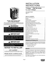
DEFROST SYSTEM DESCRIPTION
The demand defrost controller measures differential tem-
peratures to detect when the system is performing poorly
because of ice build-up on the outdoor coil. The controller
"self-calibrates" when the defrost system starts and after
each system defrost cycle. The defrost control board com-
ponents are shown in figure 19.
The control monitors ambient temperature, outdoor coil
temperature, and total run time to determine when a de-
frost cycle is required. The coil temperature probe is de-
signed with a spring clip to allow mounting to the outside
coil tubing. The location of the coil sensor is important for
proper defrost operation.
NOTE -The demand defrost board accurately measures
the performance of the system as frost accumulates on the
outdoor coil. This typically will translate into longer running
time between defrost cycles as more frost accumulates on
the outdoor coil before the board initiates defrost cycles.
DIAGNOSTIC LEDS
The state (Off, On, Flashing) of two LEDs on the defrost
board (DS1 [Red] and DS2 [Green])indicate diagnostics
conditions that are described in table 14.
TEST PINS --
DEFROST
TERMINATION
PIN SETTINGS
SENSOR
PLUG IN
(COIL & AM-
BIENT
SENSORS)
DELAY
PINS
REVERSING
VALVE
r[-_r- PI
O ®
oo,7= o
I1
0 wI
L0-PS
/Z =
f2 0u_
So
0 Iololol°l°lol°lol 0
TS_PS Or c _{ 0 _1 Yz
-- LOW
AMBIENT
THERMOSTAT
PINS
-- DIAGNOSTIC
LEDS
t 24V TERMINAL
STRIP
CONNECTIONS
Note - Compo-
nent Locations
Vary by Board
Manufacturer,
Figure 19. Defrost Control Board
DEFROST BOARD PRESSURE SWITCH CONNEC-
TIONS
The unit's automatic reset pressure switches (LOPS - S87
and HI PS - S4) are factory-wired into the defrost board on
the LO-PS and HI-PS terminals, respectively.
Page 17
14HPX SERIES
(OPTIONAL) Low Pressure Switch (LO-PS)--When the
low pressure switch trips, the defrost board will cycle off the
compressor, and the strike counter in the board will count
one strike. The low pressure switch is ignored under the
following conditions:
during the defrost cycle and 90 seconds after the ter-
mination of defrost
when the average ambient sensor temperature is be-
low 15° F (-9°C)
for 90 seconds following the start up of the compressor
during "test" mode
High Pressure Switch (HI-PS)--When the high pressure
switch trips, the defrost board will cycle off the compressor,
and the strike counter in the board will count one strike.
DEFROST BOARD PRESSURE SWITCH SETTINGS
High Pressure (auto reset) - trip at 590 psig; reset at 418.
Low Pressure (auto reset) - trip at 25 psig; reset at 55.
5-STRIKE LOCKOUT FEATURE
The internal control logic of the board counts the pressure
switch trips only while the Y1 (input) line is active, if a pres-
sure switch opens and closes four times during a Y1 (In-
put), the control logic will reset the pressure switch trip
counter to zero at the end of the Y1 (input). If the pressure
switch opens for a fifth time during the current Y1 (input),
the control will enter a lockout condition.
The 5-strike pressure switch lockout condition can be reset
by cycling OFF the 24-volt power to the control board or by
shorting the TEST pins between 1 and 2 seconds. All timer
functions (run times) will also be reset.
If a pressure switch opens while the Y1 Out line is en-
gaged, a 5-minute short cycle will occur after the switch
closes.
DEFROST SYSTEM SENSORS
Sensors connect to the defrost board through a field-re-
placeable harness assembly that plugs into the board.
Through the sensors, the board detects outdoor ambient,
coil, and discharge temperature fault conditions. As the
detected temperature changes, the resistance across the
sensor changes. Figure 20 shows how the resistance var-
ies as the temperature changes for both type of sensors.
Sensor resistance values can be checked by ohming
across pins shown in table 13.
Table 13. Sensor Tem 3./Resistance Range
Temperature Resistance values Pins/Wire
Sensor Range °F (°C) range (ohms) Color
Outdoor -35 (-37) to 120 280,000 to 3750 3 & 4
(Ambient) (48) (Black)
Coil -35 (-37) to 120 280,000 to 3750 5 & 6
(48) (Brown)
Discharge (if 24 (-4) to 350 41,000 to 103 1 & 2 (Yel-
applicable) (176) low)
Note: Sensor resistance decreases as sensed temperature increases
(see figure 20).
NOTE -When checking the ohms across a sensor, be
aware that a sensor showing a resistance value that is not
within the range shown in table 13, maybe performing as
designed. However, if a shorted or open circuit is detected,
then the sensor may be faulty and the sensor harness will
needs to be replaced.
Coil Sensor--The coil temperature sensor (shown in fig-
ure 21) considers outdoor temperatures below -35°F
(-37°C) or above 120°F (48°C) as a fault. If the coil temper-
ature sensor is detected as being open, shorted or out of
the temperature range of the sensor, the board will not per-
form demand or time/temperature defrost operation and
will display the appropriate fault code. Heating and cooling
operation will be allowed in this fault condition.
Ambient and Coil Sensor
I
m 7450
11775
_m 15425
l_am_ 19975
26200
m34375
m46275
I62700 85300
I I !
10000 30000 50000 70000 90000
RESISTANCE (OHMS)
Figure 20. Temperature/Resistance Chart
505243 04/08
Page 18
° <::::
COIL SENSORLOCATION
Figure 21. Sensor Locations
Ambient Sensor--The ambient sensor (shown in figure
21) considers outdoor temperatures below -35°F (-37°C)
or above 120°F (48°C) as a fault. If the ambient sensor is
detected as being open, shorted or out of the temperature
range of the sensor, the board will not perform demand de-
frost operation. The board will revert to time/temperature
defrost operation and will display the appropriate fault
code. Heating and cooling operation will be allowed in this
fault condition.
NOTE -Within a single room thermostat demand, if
5-strikes occur, the board will lockout the unit. Defrost
board 24 volt power "R" must be cycled "OFF" or the
"TEST" pins on board must be shorted between 1 to 2 sec-
onds to reset the board.
Defrost Temperature Termination Shunt (Jumper)
Pins--The defrost board selections are: 50, 70, 90, and
100°F (10, 21, 32 and 38°C). The shunt termination pin is
factory set at 50°F (10°C). If the temperature shunt is not
installed, the default termination temperature is 90°F
(32°C).
DELAY MODE
The defrost board has a field-selectable function to reduce
occasional sounds that may occur while the unit is cycling
in and out of the defrost mode. When a jumper is installed
on the DELAY pins, the compressor will be cycled off for 30
seconds going in and out of the defrost mode. Units are
shipped with jumper installed on DELAY pins.
NOTE - The 30 second off cycle is NOTfunctional when
jumpering the TEST pins.
Page 19
14HPX SERIES
OPERATIONAL DESCRIPTION
The defrost control board has three basic operational
modes: normal, calibration, and defrost.
Normal Mode--The demand defrost board monitors the
O line, to determine the system operating mode (heat/
cool), outdoor ambient temperature, coil temperature (out-
door coil) and compressor run time to determine when a
defrost cycle is required.
Calibration Mode--The board is considered uncalibrated
when power is applied to the board, after cool mode opera-
tion, or if the coil temperature exceeds the termination tem-
perature when it is in heat mode,
Calibration of the board occurs after a defrost cycle to en-
sure that there is no ice on the coil, During calibration, the
temperature of both the coil and the ambient sensor are
measured to establish the temperature differential which is
required to allow a defrost cycle,
Defrost Mode--The following paragraphs provide a de-
tailed description of the defrost system operation.
DETAILED DEFROST SYSTEM OPERATION
Defrost Cycles--The demand defrost control board initi-
ates a defrost cycle based on either frost detection or time.
Frost Detection--If the compressor runs longer than
34 minutes and the actual difference between the clear
coil and frosted coil temperatures exceeds the maxi-
mum difference allowed by the control, a defrost cycle
will be initiated.
IMPORTANT - The demand defrost control board will
allow a greater accumulation of frost and will initiate
fewer defrost cycles than a time/temperature defrost
system.
Time--If 6 hours of heating mode compressor run
time has elapsed since the last defrost cycle while the
coil temperature remains below 35°F (2°C), the de-
mand defrost control will initiate a defrost cycle.
Actuation--When the reversing valve is de-energized,
the Y1 circuit is energized, and the coil temperature is be-
low 35°F (2°C), the board logs the compressor run time. If
the board is not calibrated, a defrost cycle will be initiated
after 34 minutes of heating mode compressor run time.
The control will attempt to self-calibrate after this (and all
other) defrost cycle(s).
Calibration success depends on stable system tempera-
tures during the 20-minute calibration period. If the board
fails to calibrate, another defrost cycle will be initiated after
90 minutes of heating mode compressor run time. Once
the defrost board is calibrated, it initiates a demand defrost
cycle when the difference between the clear coil and
frosted coil temperatures exceeds the maximum differ-
ence allowed by the control OR after 6 hours of heating
mode compressor run time has been logged since the last
defrost cycle.
NOTE -If ambient or coil fault is detected, the board will not
execute the "TEST" mode.
Termination--The defrost cycle ends when the coil tem-
perature exceeds the termination temperature or after 14
minutes of defrost operation. If the defrost is terminated by
the 14-minute timer, another defrost cycle will be initiated
after 34 minutes of run time.
Test Mode--When Y1 is energized and 24V power is be-
ing applied to the board, a test cycle can be initiated by
placing the termination temperature jumper across the
"Test" pins for 2 to 5 seconds. If the jumper remains across
the "Test" pins longer than 5 seconds, the control will ig-
nore the test pins and revert to normal operation. The
jumper will initiate one cycle per test.
Enter the "TEST" mode by placing a shunt (jumper) across
the "TEST" pins on the board after power-up. (The "TEST"
pins are ignored and the test function is locked out if the
shunt is applied on the "TEST" pins before power-up).
Board timings are reduced, the low-pressure switch is ig-
nored and the board will clear any active lockout condition.
Each test pin shorting will result in one test event. For
each "TEST" the shunt (jumper) must be removed for at
least 1 second and reapplied. Refer to flow chart (figure 22)
for "TEST" operation.
Note: The Y1 input must be active (ON) and the "0" room
thermostat terminal into board must be inactive.
DEFROST BOARD DIAGNOSTICS
See table 14 to determine defrost board operational condi-
tions and to diagnose cause and solution to problems.
505243 04/08
Page 20
  • Page 1 1
  • Page 2 2
  • Page 3 3
  • Page 4 4
  • Page 5 5
  • Page 6 6
  • Page 7 7
  • Page 8 8
  • Page 9 9
  • Page 10 10
  • Page 11 11
  • Page 12 12
  • Page 13 13
  • Page 14 14
  • Page 15 15
  • Page 16 16
  • Page 17 17
  • Page 18 18
  • Page 19 19
  • Page 20 20
  • Page 21 21
  • Page 22 22
  • Page 23 23
  • Page 24 24

Lennox Merit 14HPX-024 Installation Instructions Manual

Category
Split-system air conditioners
Type
Installation Instructions Manual

Ask a question and I''ll find the answer in the document

Finding information in a document is now easier with AI