
Electronic Countdown Timer Switch
Cat. Nos. DT230, DT260, DT202, DT204, DT212 Lighted
Ratings: 20 A Resistive/16 A Inductive, 1,800 W Incandescent/Halogen, 600 W LED/CFL,
1,200 VA ELV/MLV/Flourescent, 1 HP or 16 A Motor/Fan, 120 VAC, 60 Hz - Single-Pole, 3-Way/Multi-Way
INSTALLATION INSTRUCTIONS ENGLISH
PK-A3461-10-00-2A
WARNINGS:
•
TO AVOID FIRE, SHOCK OR DEATH: TURN OFF POWER AT CIRCUIT BREAKER OR FUSE
AND TEST THAT THE POWER IS OFF BEFORE WIRING!
• TO AVOID PERSONAL INJURY OR PROPERTY DAMAGE, DO NOT install to control a
receptacle, or a load in excess of the specied rating.
• DO NOT use to control lighting if it is the only light source in the area.
• To be installed and/or used in accordance with electrical codes and regulations.
• If you are not sure about any part of these instructions, consult an electrician.
Installation
WARNING: TO AVOID FIRE, SHOCK OR DEATH, turn OFF power at circuit
breaker or fuse and test that the power is OFF before wiring!
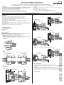
1. Identify your wires (most common shown).
NOTE: A Neutral wire is required for operation. If the wiring in the wallbox
does not resemble this conguration, consult an electrician.
You Will Need:
• Slotted/Phillips screwdriver
• Electrical tape
• Cutters
• Pliers
Features
• Easy operation with four preset buttons and one "OFF" button.
• Simple press and hold override function for 24-hour override.
• For Single-Pole, 3-Way, Multi-Way, and Multi-Timer wiring.
• Zero Cross turn-ON technology that extends the life of the switching relays
(turns ON at the minimum voltage).
• You can attach up to nine (9) DD0SR-1Z Switch Companions and up to four
(4) DD0SR-DLZ Switch Companions to this Electronic Countdown
Timer Switch.
• Color change kits are available in white, light almond, ivory, black, brown, and
gray (DTKIT-00x).
•
Available with ve countdown timer options (30 and 60 minutes, and 2, 4, 12 hours)
.
• Available in a 15A single-pole timer (Cat. No. DT1xx).
3. Test and mount.
• Restore power. Wait 20 seconds for the timer to power up.
NOTE: The bottom green LED blinks once every 5 seconds during power up.
• Press any timer button to turn the load ON.
NOTE: If load does not turn ON, refer to the "What to do if..." section.
• Turn OFF power at circuit breaker before completing the installation.
• Gently push wires into wallbox. Use the screws to attach timer to wallbox.
• Install wallplate.
• Restore power.
Single Pole
LINE
LOAD
From
Branch Circuit
NEUTRAL
GROUND
To Load
Switch Wallbox Timer Wallbox
LINE
TRAVELER 1
NEUTRAL
TRAVELER 2
LOAD
TRAVELER 1
TRAVELER 2
GROUND
From
Branch Circuit
To Timer
Wallbox
To Load
From Switch
Wallbox
NEUTRAL
GROUND
3-Way
NOTE: Timer must be installed in the same location as the load wire.
2. Wire device.
Work on one connection at a time, and connect the wires as shown.
DO NOT remove
the insulating label.
Single Pole
TRAVELER
(Yellow/Red)
LOAD
(Blue) LOAD
LINE NEUTRAL
GROUND
GROUND
(Green)
From
Branch Circuit
To Load
GROUND
GREEN
LINE
BLACK
3-WAY
YELLOW/RED
LOAD
BLUE
NEUTRAL
WHITE
NEUTRAL
(White)
LINE
(Black)
DD0SR-1Z
Switch Companion
DT2xx
Timer To Load
From
Switch Companion
GROUND
GROUND
(Green)
TRAVELER
(Yellow/Red)
LOAD
TRAVELER 2
TRAVELER 1
LOAD
(Blue)
GROUND
From
Branch Circuit
NEUTRAL
NEUTRAL
(White)
NEUTRAL
LINE
TRAVELER 2
TRAVELER 1
To Timer
GROUND
GREEN
LINE
BLACK
3-WAY
YELLOW/RED
LOAD
BLUE
NEUTRAL
WHITE
LINE
(Black)
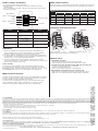
3-Way Wiring with DD0SR-DLZ Switch Companion
3-Way Wiring with DD0SR-01Z Switch Companion
3-Way Wiring with Two Timers (DT2xx)
Timer 1
LINE
Timer 2
To Load
From Timer 1
GROUND
TRAVELER
(Yellow/Red)
LOAD
TRAVELER 1
(Yellow/Red)
TRAVELER 2
TRAVELER 1
TRAVELER 1
TRAVELER 2
LOAD
(Blue)
LOAD
(Blue)
GROUND
(Green)
To Timer 2
GROUND
From
Branch Circuit
NEUTRAL
(White)
NEUTRAL
NEUTRAL
(White)
NEUTRAL
GROUND
GREEN
LINE
BLACK
3-WAY
YELLOW/RED
LOAD
BLUE
NEUTRAL
WHITE
LINE
(Black)
GROUND
GREEN
LINE
BLACK
3-WAY
YELLOW/RED
LOAD
BLUE
NEUTRAL
WHITE
LINE
(Black)
DD0SR-DLZ
Switch Companion
DT2xx
Timer To Load
From
Switch Companion
GROUND
GROUND
(Green)
TRAVELER
(Yellow/Red)
LOAD
TRAVELER 2
TRAVELER 1
LOAD
(Blue)
GROUND
From
Branch Circuit
NEUTRAL
NEUTRAL
(White)
NEUTRAL
LINE
TRAVELER 2
TRAVELER 1
To Timer
GROUND
GREEN
LINE
BLACK
3-WAY
YELLOW/RED
LOAD
BLUE
NEUTRAL
WHITE
LINE
(Black)
DO NOT remove
the insulating label.
CAUTIONS:
• DO NOT use disinfecting products, including foggers, sprays or other types of atomized
cleaning agents.
• DO NOT spray liquid onto the product.
• To clean, use a damp cloth with mild soap.
• No user serviceable components. DO NOT attempt to service or repair.
• Use this device WITH COPPER OR COPPER-CLAD WIRE ONLY.
WEB VERSION

For Technical Assistance Call: 1-800-824-3005 (USA Only) or 1-800-405-5320 (Canada Only) www.leviton.com.
© 2023 Leviton Mfg. Co., Inc.
FCC STATEMENT:
This device complies with Part 15 of the FCC Rules. Operation is subject to following two conditions: (1) this device may not cause harmful interference, and (2) this device must accept
any interference received, including interference that may cause undesired operation of the device. This equipment has been tested and found to comply with the limits for a Class B
Digital Device, pursuant to Part 15 of the FCC Rules. These limits are designed to provide reasonable protection against harmful interference in a residential installation. This equipment
generates, uses, and can radiate radio frequency energy and, if not installed and used in accordance with the instructions, may cause harmful interference to radio communications.
However, there is no guarantee that interference will not occur in a particular installation. If this equipment does cause harmful interference to radio or television reception, which can be
determined by turning the equipment OFF and ON, the user is encouraged to try to correct the interference by one or more of the following measures:
• Reorient or relocate the receiving antenna.
• Connect the equipment into an outlet on a circuit different from that to which the receiver is connected.
• Increase the separation between the equipment and the receiver.
• Consult the dealer or an experienced radio/TV technician for help.
LIMITED 5 YEAR PRODUCT WARRANTY
For Leviton’s limited 5 year product warranty, go to www.leviton.com. For a printed copy of the warranty you may call 1-800-323-8920 or write to Leviton Manufacturing Co., Inc.,
Att: Customer Service Dept., 201 North Service Road, Melville, New York 11747.
Patents covering this product, if any, can be found on www.leviton.com/patents.
Leviton and the Leviton logo are the registered trademarks of Leviton Manufacturing. Co., Inc.
FOR CANADA ONLY
For warranty information and/or product returns, residents of Canada should contact Leviton in writing at Leviton Manufacturing of Canada ULC the attention of the Quality Assurance
Department, 165 Hymus Blvd, Pointe-Claire (Quebec), Canada H9R 1E9 or by telephone at 1 800 405-5320.
FCC CAUTION:
Any changes or modifications not expressly approved by Leviton Manufacturing Co., Inc., could void the user's authority to operate the equipment.
IC STATEMENT
This device complies with Industry Canada licence-exempt RSS standard(s). Operation is subject to the following two conditions: (1) this device may not cause interference, and (2) this
device must accept any interference, including interference that may cause undesired operation of the device.
Remove Replace
Changing Your Device Color
Color change kits are available in White (W), Light Almond (T), Ivory (I),
Black (E), Brown (B), and Gray (G) (DTKIT-00x).
Mode Location Status
Power Up Next to OFF button Blinks once every
5 seconds.
Load OFF Next to OFF button ON
Load ON Next to Button
1, 2, 3, or 4 ON
24-Hour Timer Override Next to Button 1 Blinks once per second.
Last Minute Load Is ON Next to Button 4 Blinks once per second.
Operation
1. To turn the load ON, press one of the timer buttons. Each button has a
preset countdown time. The green LED adjacent to the selected button
illuminates, and the load stays on for the selected time period.
2. To select a different countdown time, press the button that corresponds to
the desired time. The LED adjacent to the selected button illuminates, and
the load stays on for the newly selected time period.
3. To turn the load OFF, press the OFF button, or wait until the selected
amount of time elapses. The LED adjacent to each button turns OFF as time
passes to the next lower preset level.
Timer Override
To override the timer countdown, press and hold the top button for more
than 5 seconds.
The LED blinks once per second to indicate the timer is in the
EXTENDED ON state.
The timer automatically turns OFF after 24 hours. To exit
the EXTENDED ON state, press any timer button or the OFF button.
Model Countdown Timer Options
Button 1 Button 2 Button 3 Button 4 Button 5
DT230 30 minutes 15 minutes 10 minutes 5 minutes Off
DT260 60 minutes 30 minutes 20 minutes 10 minutes Off
DT202 2 hours 1 hour 30 minutes 15 minutes Off
DT204 4 hours 2 hours 1 hour 30 minutes Off
DT212 12 hours 8 hours 4 hours 2 hours Off
Multi-Location Control
The Timer can be turned ON or OFF from any of the Wired Switch Companion
locations. The default ON time when a wired switch companion is pressed to
turn the load ON is the last countdown time selected.
The timer can be controlled from up to nine (9) other locations with wired
switch companions (without LEDs - DD0SR-1Z), or up to four (4) other
locations with wired switch companions (with LEDs - DD0SR-DLZ).
Multi-Timer Control
When the timers are connected in a 3-way control, either timer can turn ON or
OFF the load with both timers showing the same countdown LED sequence.
What to do if...
• Intermittent operation
- Check that the load does not have a bad connection.
- Check if wires are secured firmly to the leads of timer switch.
• Load does not turn ON and Locator LED does not turn ON
- Check if the circuit breaker or fuse has tripped.
- Check if the load has burned out.
- Make sure the Neutral connection is wired properly.
• Wired Switch Companion does not operate load.
- Make sure that the total wire length does not exceed 300 ft (90 m).
- Make sure to use a Neutral wire with a Wired Switch Companion.
LED Location and Status
• Four (4) timer buttons and an OFF button.
• Each timer button has an adjacent green LED to indicate the current
countdown time.
• The green bottom Locator LED is ON when the load is OFF, and it is OFF
when the load is ON.
LED Indicator Lights
Locator LEDOFF Button
Button 4 - Shortest ON Time
Button 3
Button 2
Button 1 - Longest ON Time
Timer Buttons
WEB VERSION
-
 1
1
-
 2
2


Leviton DT202-1LW Instruction Sheet
- Category
- Motorcycle Accessories
- Type
- Instruction Sheet
Ask a question and I''ll find the answer in the document
Finding information in a document is now easier with AI