Page is loading ...

•
•
Output Wattage: 40W Max.
•
Universal Voltage: 120-277V , 50/60Hz~
•
Output Current: 250-1400mA
•
Output voltage range of 11-55V
General Specifications
This Driver Will Operate The Following LED Modules: Any LED module designed to accept input voltage range of 11-55VDC and can operate
up to current of 250-1400mA.
Page 1 of 6
2017-736-1 Rev C
MECHANICAL DATA 100%-1%,0% LiFePO4 E313578
•
Compact case with side leads
MECHANICAL DATA
Case Tolerance=±0.02"
FHSAC1-UNV-40C
FHSBATL2-3.2L
LED Driver with integrated emergency backup
FHSAC1-UNV-40C
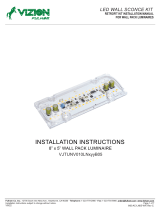
INSTALLATION INSTRUCTIONS
Input Voltage
Input Current
Input Power
Standby Input Power
Output Current
Output Voltage Range
Output Power
Number of Output Channels
RFI/EMI
Output Type
Ambient Operating Temperature Range
Input Surge Protection
Protections
120-277VAC, 50/60Hz
0.43A @ 120VAC
54W
<0.85W
Constant Current
11-28VDC ( 250-1400mA ) , 11-40VDC ( 250-1000mA ) , 11-55VDC ( 250-730mA )
40W Max. ( Figure 1 )
1 Channel
FCC Part 15A Non-Consumer
LED Class 2
Line-Neutral 3kV , Line & Neutral-Gound 6kV , Ring Wave ANSI/IEEEC62.41
Input Current Protection
Output Open Circuit Protection
Output Short Circuit Protection
Output To Ground Short Circuit Protection
250-1400mA [ TPSB 100 ( Program Box ) , Figure 1 ] ; Record New Setting On 1"x0.5" Label
Battery Type LiFePO4 6.4VDC (Part# FHSBATL2-3.2L)
Battery Capacity Available
Max. Case Temperature
3200mAh
Battery Recharge Time 12 Hours
Driver Type
Power Factor >0.9
<20%
THD
5W or 10W @ Emergency Mode (Min. 180 Minutes @ 5W, Min. 90 Minutes @ 10W)
Sound Rating A
Over Temperature Protection
Overload Protection
Dimming Controller Type / Dimming Range 0-10V / 100% - 1%,0% ( Figure 2 ) / Custom Dimming Curve / Dimmed To Off
Service Life
Approvals / Class
50,000 hours
RoHS , cURus , CEC , Dry or Damp Locations
0°C to 48°C(32°F to 118.4°F)
85°C (185°F)
Test Switch Remote Mounting Distance 20' (6m) Max.
Fulham extends a limited warranty to the original purchaser or first user for a period of 5 years @ Tc 63°C from the date of manufacture when properly
installed and operated under normal conditions of use. For complete terms and conditions, please refer to the Warranty Center at www.fulham.com.
Specifications subject to change without notice.

Manufacturer:
North China
Fulham Electronic Co. Ltd.
No. 9 Xingchang Road, Nanshao Zhen Changping Science Park, Beijing, P.R. China
Fulham Head Quarters:
Fulham Co., Inc
12705 South Van Ness Ave.
Hawthorne, CA 90250
SAVE THESE INSTRUCTIONS
MECHANICAL DATA 100%-1%,0% LiFePO4 E313578
Page 2 of 6
2017-736-2 Rev C
INSTALLATION INSTRUCTIONS
FHSAC1-UNV-40C
Important Safety Instructions
When using electrical equipment and this lighting device basic safety precaution should
be followed at all times including but not limited to the following:
·CAUTION: Do not let power supply cords touch hot surfaces.
·CAUTION: Do not mount near gas or electric heaters.
·IMPORTANT: An un-switched AC power source of 120VAC to 277VAC is required for the
·This device is designed for use in fixtures listed for dry and damp locations.
PLEASE READ CAREFULLY AND FOLLOW ALL INSTRUCTIONS FOR YOUR OWN SAFETY
·CAUTION: Make sure all electrical connections conform to the National Electrical Code and all applicable local
regulations.
·CAUTION: Battery is rechargeable LiFePO4 type and must be recycled or disposed of properly.
·CAUTION: Do not use this emergency driver with accessory equipment other than recommended by
manufacturer; failure to follow this may cause an unsafe condition. Servicing should only be performed
by qualified service personnel.
·CAUTION: Do not use this emergency driver for other than intended use.
·CAUTION: Equipment should be mounted in locations and at heights where it will not readily be subjected
to tampering by unauthorized personnel.
yellow/black and white leads.
·IMPORTANT: A switched or un-switched AC power source of 120VAC to 277VAC is acceptable
for the black lead only.
TESTING SYSTEM: The emergency battery requires a minimum charge time of one (1) hour before testing the circuit.
A minimum of twelve (12) hours is required for a full charge.
ASSEMBLY and FIELD INSTALLATION WIRING: WARNING: AC power must be off before proceeding with assembly,
installation or servicing of emergency driver. Additionally ensure that the battery is disconnected (Battery Switch set to OFF).
RATED EMERGENCY OPERATION: Ninety (90) minutes for the 10W load or one hundred eighty (180) minutes for the 5W
load. The 10W or 5W option is determined by the position of Dip Switch 1 (Emergency Power Selection Switch).
IMPORTANT: In order to maintain proper operation and warranty coverage, the battery must be recharged once
per year prior to installation.
Fulham extends a limited warranty to the original purchaser or first user for a period of 5 years @ Tc 63°C from the date of manufacture when properly
installed and operated under normal conditions of use. For complete terms and conditions, please refer to the Warranty Center at www.fulham.com.
Specifications subject to change without notice.

MECHANICAL DATA 100%-1%,0% LiFePO4 E313578
FHSAC1-UNV-40C
Page 3 of 6
2017-736-3 Rev C
LED OUTPUT
CHANNEL
PINK( - )
PURPLE( + )
Un-Switched Line
WHT(COMMON)
YEL/BLK( L )
BLK( L )
Switched or
Un-Switched Line
LED OUTPUT LEAD
TEST SWITCH / LED INDICATOR
DIMMING
LED MODULE WITH NTC
0-10V
(NTC OPTIONAL)
LED MODULE
RIGHT VIEW
1-Emergency Power Switch:
5W or 10W(10W @ ON)
ON
2-Self-Diagnostic:
Effective @ ON
ON OFF
1 2
BATTERY SWITCH
Emergency
Power Switch
INPUT SIDE LENGTH
BLACK 12"[304.8mm]
WHITE 12" [304.8mm]
YEL/BLK 16"[406.4mm]
OUTPUT SIDE LENGTH
LED OUTPUT 8"[203.2mm]
TEST LEAD 8"[203.2mm]
PURPLE 12"[304.8mm]
PINK 12"[304.8mm]
FHSAC1-UNV-40C
FHSBATL2-3.2L
NTC INPUT LEAD
NOTE:1.The driver must be grounded.
2.Once assembly, installation or servicing is complete,
set the BATTERY SWITCH to the ON position.
A Mounting the LED Driver
B Wiring diagram
Case
Length
Dimensions
Width
Height
6.32” [160.5mm]
3.05” [77.6mm]
1.14” [29mm]
INSTALLATION INSTRUCTIONS
NOTE: This driver has two mounting holes, one on each side. Two holes are needed for mounting.
Ø
Fulham extends a limited warranty to the original purchaser or first user for a period of 5 years @ Tc 63°C from the date of manufacture when properly
installed and operated under normal conditions of use. For complete terms and conditions, please refer to the Warranty Center at www.fulham.com.
Specifications subject to change without notice.
Note: Pink or Gray dimming wire
provided. use interchangeably.
Note: Pink or Gray dimming wire
provided. use interchangeably.

MECHANICAL DATA 100%-1%,0% LiFePO4 E313578
FHSAC1-UNV-40C
Page 4 of 6
2017-736-4 Rev C
BATTERY REPLACEMENT/SERVICING INSTRUCTION
Remove screws Remove battery cover
Disconnect the connector
Pull out the battery wiring
Replace with new battery
Warning: Disconnect power when servicing fixture.
Re-assemble battery cover with screws
Completed Assembly Exploded View
SAVE THESE INSTRUCTIONS
STEP 1: Remove the cover
STEP 2: Install new battery and re-assemble battery cover
INSTALLATION INSTRUCTIONS
C Mounting the LED Driver
Fulham extends a limited warranty to the original purchaser or first user for a period of 5 years @ Tc 63°C from the date of manufacture when properly
installed and operated under normal conditions of use. For complete terms and conditions, please refer to the Warranty Center at www.fulham.com.
Specifications subject to change without notice.

MECHANICAL DATA 100%-1%,0% LiFePO4 E313578
FHSAC1-UNV-40C
Page 5 of 6
2017-736-5 Rev C
Guideline on calculating emergency illumination level
The purpose of this guideline is to identify the illumination level of the LED luminaire when used with Fulham's
FHSAC1-UNV-40C LED emergency driver. The path of egress illumination level during emergency operation is
determined by types of luminaires, Luminaire Efficacy, Luminaire Mounting Height, Emergency Power and some
other effects in real application.
Step 1: Select an LED Luminaire, and make sure the LED light source is electrically compatible with Fulham's LED
emergency driver. Get the Light Distribution data (usually an .ies file) and Rated Efficacy data (lumen per watt)
from luminaire supplier.
If the luminaire is DesignLights ConsortiumTM (DLC) compliant, you can also get the efficacy information from
DLC website.
- Open DLC Qualified Product List(QPL) database search page: https://www.designlights.org/search/
- Searching keywords by model, brand name or manufacturer for the luminaire used.
- Find the “Efficacy” data listed on website or calculated by dividing “Light output” by “Wattage”, the efficacy
value should be shown in lumen per watt (lm/W).
If the luminaire is ENERGY STAR compliant, you can also get the luminaire efficacy information from ENERGY
STAR website.
- Open ENERGY STAR certified Light Fixtures database search page:
https://www.energystar.gov/productfinder/product/certified-light-fixtures/results
- Searching keywords by model, brand name or manufacturer for the luminaire used.
- Find the “Energy Efficiency” data listed on website. If it is showed as “Measured at the Source”, please
contact with luminaire supplier for additional light loss for this light source inside the fixture. The value should be
shown in lumen per watt (lm/W).
Step 2: Determine the Emergency Power and calculate the Emergency Light Output.
FHSAC1-UNV-40C is programmable output; setting a proper Emergency Power is vital to achieve desired
illumination.
Emergency Light Output is equal to the Emergency Power multiply by luminaire efficacy. For example, if the
luminaire is 120lm/W and in 3W emergency operation, the total Emergency Light Output is 120lm/W * 3W = 360lm.
Step 3: Use industry lighting design software to calculate the illumination level according to the luminaire layout in
room, luminaire mounting height, the original .ies file and Emergency Light Output calculated above. If the
illumination level cannot meet life safety codes, go back to Step2 to use a higher Emergency Power or go back to
Step1 to select a higher efficacy luminaire or use more luminaires in the room.
Fulham's FHSAC1-UNV-40C LED emergency driver is compliant with UL 924 standard, according to UL test data,
Table 1 and Table 2 below give basic indication to determine the min. Emergency Power and Luminaire Max.
Mounting Height for 1 foot-candle illumination based on a single luminaire with typical Lambertian distribution.
It is the light designer/ construction contractor's responsibility to validate the real illumination level on site, to assure
the emergency light illumination level is in accordance with the requirement of Federal, state and local municipal
codes. It may diff to the theoretical calculation or simulation on computer.
EM 5W EM 10W
80 80 10.1 ft 13.9 ft
100 11.2 ft 15.4 ft
120 12.1 ft 16.8 ft
140 13.0 ft 18.1 ft
160 13.9 ft 19.3 ft
180 14.6 ft 20.4 ft
5.0 W
Table 1. Min. EM Power for 1fc @ 10ft vs. Luminaire Efficacy Table 2. Max. Mounting Height vs. Luminaire Efficacy
Luminaire Efficacy
(lm/W)
Min. EM Power to achieve
1 fc @ 10ft Mounting Height
Luminaire Efficacy
(lm/W)
Max. Mounting Height for 1fc
INSTALLATION INSTRUCTIONS
Fulham extends a limited warranty to the original purchaser or first user for a period of 5 years @ Tc 63°C from the date of manufacture when properly
installed and operated under normal conditions of use. For complete terms and conditions, please refer to the Warranty Center at www.fulham.com.
Specifications subject to change without notice.

Page 6 of 6
2017-736-6 Rev C
MECHANICAL DATA 100%-1%,0% LiFePO4 E313578
FHSAC1-UNV-40C
SELF DIAGNOSTIC INSTRUCTIONS / OPERATION:
TEST SWITCH INDICATOR STATUS:
If Dip Switch 2 (Self-Diagnostic Switch) is set to the OFF position:
The self diagnostic feature is disable. A functionality test shall be manually conducted every thirty(30) days to ensure
the emergency LED light source illuminates as intended. A full discharge test shall be conducted once a year; the LED
light source shall illuminate for a minimum of ninety (90) minutes for the 10W load (Dip Switch 1 is set to the ON position)
or one hundred eighty (180) minutes for 5W load (Dip Switch 1 is set to the OFF position).
If Dip Switch 2 (Self-Diagnostic Switch) is set to the ON position:
The self diagnostic feature is enable .The emergency LED driver will conduct a self check for thirty (30) seconds every
thirty (30) days; and ninety (90) minutes or one hundred eighty (180) minutes self check every 12 months. After every self
check the LED indicator light will indicate a status signal. A single self-diagnostic test can be activated by pressing the test
switch three (3) times. Refer to Indicators Status Table for details.
When user toggle the Dip Switch, the LED indicator on Switch button would flash 3 times, 2.5S ON/0.5S OFF for Enabled,
while 0.5S ON/2.5S OFF for Disabled.
LED Indicators Status EM Driver Status/M ode
• Solid Green Sys tem OK/AC OK(Self-diagnos tic Enabled or D is ab led).
• Slow Flas hing R ed, 4s on/1s o ff Battery no t de tected, ch eck b atte ry s witch or conne ctio n.
• Flas h ing R ed, 1s on/1s o ff Battery Failure, rep lace b atte ry.
• Flas h ing Green, 1s on/1s off Self-Diagnos tic tes t underw ay.
• Fas t Flas hing R ed, 0.1s on/0.1s off Abnorm a l driver perform ance, replace driver.
• Very Slow Flas hing Red, 4s on /4s off Over tem perature.
• N one. Both LED s OFF Norm al working in EM m ode.
• Green/Red alte rnative flas hing, 1s green/1s red. No loa d o r output over voltage protection triggered.
Programming:
This driver can be programmed using the TPSB-100(E). Programming features include the following:
* Output Current: 250-1400mA
* Dimming Curve
* LED NTC Thermal Protection
INSTALLATION INSTRUCTIONS
1.
2.
EM Test: Press and hold test button (>1s)to enter EM mode for testing in normal AC powered. Subsequent tests can be
performed after a minimum 20 Second delay in pressing the Test Switch.
Manual Self-Diagnostic (When Self-Diagnostic Enabled - Dip Switch 1 set to the ON position): After charging twelve
(12) hours or battery fully charged, quickly press the test button three (3) times within three (3) seconds to force the
controller to enter a Self-Diagnostic cycle. To quit the self-diagnostic cycle after engaged press and hold the test button
for ten (10) seconds.
TEST SWITCH OPERATIONS:
Fulham extends a limited warranty to the original purchaser or first user for a period of 5 years @ Tc 63°C from the date of manufacture when properly
installed and operated under normal conditions of use. For complete terms and conditions, please refer to the Warranty Center at www.fulham.com.
Specifications subject to change without notice.
/